Winged "Spartak". Chapter 1. The main
Among the aircraft designed and built under the leadership of Viktor Fedorovich Bolkhovitinov (1899 – 1970), the most well-known are the four-engine bomber DB-A (it has already been described) and the BI-1 rocket fighter. But the elegant multi-purpose combat aircraft, equipped with two twin M-103 engines, for some reason always remained in the shadows. In the period of creation of this experimental apparatus, the notations BBS (short-range speed bomber), BB (Bolkhovitinov bomber), LB - C (light bomber - Spark) and even SSS (ultra high-speed aircraft) were used. In practice, its shortest designation was fixed - the aircraft "C". "Stalin", "Spark", "Spartak" - here are a few options to this day to decipher this single letter "C". The author does not insist on any of them, therefore he invites the reader to choose the most liked one himself.

Home stories It refers to 1933, the period of discussion of the design options for the fighter JNUMX. In particular, at the meeting with the head of the Air Force Ya. I. Alksnis in December 17, among others, the project of the two-seat I-1933, defined as DI-17, was considered. Due to doubts about its need, specific decisions on such a two-seat vehicle have not been made for a long time. At some stage in the development of events, the option of installing two twin engines on the DI-7, one after another rotating two propellers in opposite directions, arose. With respect to such a motor installation, the definition of “mechanical Spark” was used. Interest in this topic at the beginning of 7 intensified in connection with the deployment of design work to create a record high-speed aircraft. As a result, the motor plant No. 1935 was given the task of developing a “mechanical pairing” of M-26 engines (then M-100).
In the form of a small digression, it makes sense to devote some space to describing the very problem of articulated engines. It is clear that the connection of two engines one after the other into a single power unit made it possible, first of all, to significantly reduce aerodynamic drag. In addition, the studies carried out, and simply elementary considerations, suggested to designers the idea of the advantages of propellers assembled on the same axis and rotating in opposite directions. The total reactive moment of such screws was zero, as a result of which there was no need for aerodynamic compensators. In a curved flight, for example, a bend, the gyroscopic moment of each individual propeller was eliminated, which increased the maneuverability of the aircraft. Then - the air flow, twisted by the front screw, was straightened by the rear screw, which created the possibility of increasing the efficiency of the entire propeller group. Moreover, the rectified flow provided a symmetrical flow around the aircraft itself, which favored the improvement of its controllability during takeoff and landing.

These theoretical considerations required practical evidence. And such evidence appeared very soon. For the first time, the extraordinary capabilities of articulated engines and coaxial propellers were demonstrated in triumphal fashion by the Italian record seaplane Mackey - Castoldi M-72 (Macchi MC72).
This aircraft was built specifically for participation in popular international competitions for the Schneider Cup, where world flight speed records were often set. The peculiarity of the competitions was the performance of exclusively seaplanes on them, and the vast majority of them were double-float machines. The pilots participating in this international championship had to start taking off at right angles to the wind, as the unbalanced jet moment of a single propeller forced one of the floats to completely submerge, resulting in an almost full turn of 90 ° to the wind direction at the start. The described maneuver was forced, complicated in execution and presented a considerable danger. Obviously, this flaw was one of the motivations that led designer Mario Castoldi to use twin engines and coaxial screws on his M-72. Conducted in the process of creating a seaplane studies have shown that we can expect a significant increase in speed. And although the rotation of the screws on the M-72 was not synchronized (each screw was rotated from a separate engine, so they always had some difference in speed), success was achieved. In the summer of 1934, the Italian M-72 set a world speed record of 709 km / h, which lasted until 1939.
But back to the description of the problems and achievements of the Soviet aviation. The final task for the manufacture of a “mechanical coupler” appeared after the development of licensed Ispano Suiza engine engines in Rybinsk, and the beginning of their production under the Soviet designation M-26. At first they experimented with these engines, then switched to the more powerful M-100. In both cases, the so-called cannon engines were used - the engine shaft in them was made hollow for installing a rapid-firing gun.
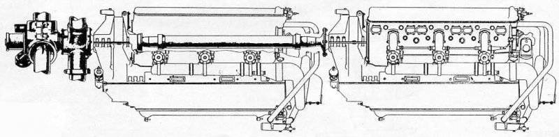
So, two M-103P engines were installed on the same rigid engine mount. The rear engine shaft passed through the front hollow shaft and rotated the front propeller. And the front engine rotated the rear propeller. Tests of such pairing of M-103P engines at the stand were carried out in 1936 with quite encouraging results. It was decided to build a plane for the installation, and Bolkhovitinov got the order for it.
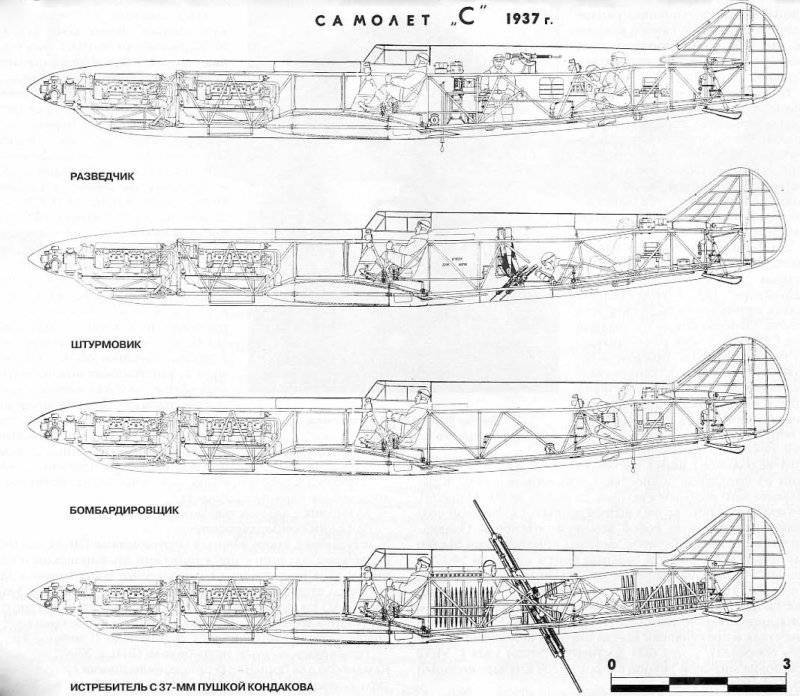
Military engineer 1 rank Viktor Fedorovich Bolkhovitinov in 1937 was the chief designer of the Kazan Aviation Plant No. 124, where they laid a series of DB-A. bombers. With the receipt of a new and very interesting task, many ideas on technology and armament immediately appeared. That is why the designer's proposals were initially expressed in the form of a preliminary draft submitted to 23 on November 1937 for consideration. In total, four versions of the aircraft were proposed:
1. Scout with a range of up to 2200 km.
2. Middle bomber.
3. An attack aircraft, armed with ten ShKAS machine guns. (After consulting with the designers Mozharovsky and Venevidov, the weapons and methods of attack of the target changed. These gunsmiths suggested using twin machine guns UltraShKAS with a rate of fire of 10000 shots per minute. Machine guns mounted on the swinging node allowed to cover with fire a strip of ground 25 m wide).
4. "Bomber" fighter (BI) with 37 – mm gun designed by Kondakov to fight enemy bombers. The gun had two barrels firing for mutual destruction of recoil simultaneously in opposite directions. Shooting from one barrel was carried out by shells, from the other - by weight blanks. The firing range of the 37 – mm gun was 4 km, and the charging and gunner were on board the aircraft for its maintenance.
During the discussions and revisions of the project, the Bolkhovitinov aircraft turned into a double high-speed bomber with defensive armament in the form of a single ShKAS machine gun. For effective protection of the tail section, the vertical tail was made separated. Offensive armament was supposed to be two ShKAS in the wings (or under the wings), but never installed.
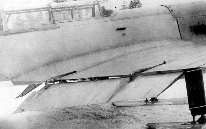
The high-speed bomber “C” was designed according to the TTN Air Force 1937 g. According to these requirements, the maximum speed of the aircraft was 640 km / h. However, theoretical calculations promised even more - 668 km / h at an altitude of 5250 m. There were grounds for optimism: the plane had a long, elongated fuselage, a small wing and a small area with a new, high-speed BBS profile. To reduce the landing speed, special retractable flaps, the so-called “Fowler type” flaps, were used. In general, the design used the most progressive, the fuselage was assembled from four carefully made and well-joined panels - the top, bottom and two side. The wing had a smooth trim; it had reinforcements in the form of a reinforcing inner corrugation.

The model of the aircraft was considered 16 June 1938 in Kazan - at the place of the main location of the main designer Bolkhovitinov. However, Viktor Fedorovich was soon able to achieve a transfer to Moscow - the design bureau was relocated in August – September 1938. Those who arrived in the Fotolet workshops in the territory of Plant No. 84 were accommodated, and the organization itself soon became known as Aviation Plant No. 293.
In a special government decree concerning the design and construction of a new aircraft, the first instance of a nearby high-speed bomber (BBS) was to be tested in August 1939, the second copy - in December 1939.
The direct performers of the assignment, the chief designer Bolkhovitinov and the director of the plant No. 84 Yarunin, had to fulfill the following requirements for the aircraft:
The aircraft’s weaponization was indicated: a ShKAS machine gun in the upper defensive installation and 4 bomb cartridges AK-1М in the fuselage to accommodate four 100 – kilogram bombs.
In accordance with the accepted deadlines for the Bolkhovitinov aircraft, aircraft plant No. 26 (represented by director Balandin and chief designer Klimov) was to deliver to plant No. 84 the first “pair” of M-103 engines to 5 June 1939, following June 10, two more 1 August 1939
In total, under the designation "C" built two experimental apparatus: C-1 and C-2. The first C-1 was prepared in the second half of 1939. It was equipped with one M-103 engine with a VISH-2 propeller. The purpose of the C-1 test was to assess its flight performance - stability, controllability and take-off and landing characteristics. In addition, it was necessary to evaluate the systems and equipment, determine the internal and external pressures on the engine hood to allow the second car to reach maximum flight speeds.
C-1 entered the tests at the end of 1939. The Armament did not have any special equipment, it was installed on a non-removable ski landing gear. His first flight took place on 26 in January 1940, the pilot B. Kudrin flew. In total, before the end of tests in March, 1940 managed to perform 29 flights, the maximum speed of 400 km / h was reached. In addition to Kudrin, the pilot Kabanov participated in the flights from the Scientific Research Institute of the Air Force, so the tests were counted as joint - factory and state. The flight assessment was quite acceptable, there were practically no defects identified during the testing process, and there were no routine modifications.
It was admitted that C-1 is in all respects fully aircraft driven; piloting techniques are available to medium-skilled pilots. The obtained test results of this machine made it possible to boldly embark on flights of the twin-engine C-2 variant. In the conclusion of the C-1 report, it was said: “To consider it necessary, without waiting for the end of the test of the aircraft No. 2, to start preparing the drawing facilities for building an experimental series of aircraft”.
Later, at the first experimental C-1, the M-103 twin engines were installed using the engine life, and the aircraft in this design was used for full-scale studies in the TsAGI wind tunnels.
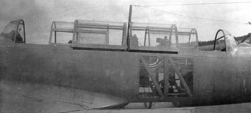
Even before the end of testing the first machine from 20 in March 1940, the flights of the second experienced C-2 began. The goal was specific: “To verify the compliance of the actual flight data of the aircraft and its armament with the tactical and technical requirements and assess the possibility of adopting this aircraft for the Air Force.” The very formulation of the task itself indicated that the second machine was fully equipped and armed. In the space between the cockpit of the pilot and navigator was a bomb bay that accommodates 4 FAB-100. The loading of bombs took place through the opening fragment of the cockpit canopy using a special crane - beam. In addition to the indicated internal placement of the aerial bombs, a suspension of four FAB-100s on the outer holders under the wing was assumed.
The navigator's cockpit had glazing in the floor and on the sides to improve the view, it was equipped with all the main navigation instruments, sight, bomb rammer, RSB radio station. Immediately behind the navigator’s cabin was the AFA-1 camera. The crew cabin bookings did not have.
The C-2 was equipped with two twin M-103P engines, each with an 960 power. with. at a height of 4000 m, with propellers - automata VISH - KB Air Force. The exhaust pipes of jet-type engines, they were made in the form of welded manifolds, combining exhaust from three cylinders. The gas tanks are unprotected, with a total capacity of 660 l, in the amount of three tanks placed in the fuselage, immediately behind the engines. Water cooling radiators for both engines were placed in a single unit under the fuselage. Here, in the same tunnel with water radiators, there were two cylindrical 8 – inch oil radiators. The back of all this “beard”, prominently protruding from the aircraft, was equipped with a single movable door to adjust the cooling of all radiators.
Supplement the brief description of the aircraft should be some details regarding the features of its device. The wing was connected to the fuselage by four knots, called a caisson type design, its socks and tails were detachable throughout their span, attached to the central part by ramrods. The tail stabilizer is mobile, its shift control could be carried out in flight using a steering wheel from the cockpit. The design of the tail assembly is similar to that of the wing.
State tests of the second “C” aircraft, which began immediately after the first flights, continued until July 25 1940. They flew: the pilot of the Air Force Research Institute, Colonel A. I. Kabanov, and the navigator P. I. Nikitin. In flight, this crew reached a maximum speed of 570 km / h at the calculated altitude.
The flight assessment of the C-2 was generally positive, and it was recognized that piloting control was simple and fairly easy. The plane was well listened to the rudders on all flight modes, up to maximum speed, planning, climb and turns. However, the high specific load on the wing (on the first machine was 171 kg / m2, on the second, due to increased flight weight, it was 246 kg / m2) sharply worsened the takeoff and landing characteristics of the aircraft. After breaking off at a speed of 200 km / h, he then slowly accelerated to the most favorable climb rate of 300 – 310 km / h. The forest surrounding the NII VVS airfield was at a distance of 2 km from the launch site, but the plane literally passed over the treetops when it took off. Attempts to use the Fowler flaps as efficiently as possible, which were supposed to increase the wing carrying capabilities and reduce the flight speeds of the aircraft, did not produce any tangible positive results, and they were abandoned.
Landing was no less difficult. C-2 planned with fully open flaps at a speed of 240 km / h, landing quickly lost speed and became unstable. According to testers' testimonies, the complex takeoff and landing qualities of the new aircraft made it available only to highly qualified pilots. An additional drawback was considered his too long nose, making it difficult for the pilot to get an overview when entering the target. At the navigator, the downward view was hampered by the fact that the glazing was sprayed with oil, covered with dust and dirt during takeoff. The loading of bombs through the opening canopy turned out to be inconvenient.
According to the test results of the C-2, it was recognized that the maximum speed reached by 570 km / h was lower than that required by 70 km / h, and the landing speed 165 – 168 km / h was too high, the flight range was lower than stated: 700 km instead of 1200 km according to the Committee’s decision Defense Although for all the above reasons, the C plane failed to withstand state tests, it was also noted: “... the C plane is an experimental aircraft that was the first in the Union to solve the problem of increasing the power of the propeller group without increasing drag, and this task was almost solved by the designer . The combination of two engines in one unit with success can be used on fighter aircraft with pushing screws and on the bombers of a normal twin-engine scheme. Considering the availability of a maximum speed of 570 km / h at an altitude of 4600 m and the possibility of raising it, as well as the possibility of eliminating defects for which the aircraft could not withstand state tests, the Red Army Air Force Institute considers it necessary to first improve takeoff and landing properties and then re-show aircraft for control tests at the Scientific Research Institute of the Air Force for February 1 1941.
Consider it necessary to carry out the following work in TsAGI and CIAM:
1. Identify the characteristics of coaxial screws.
2. Reveal the best working conditions for twin motors on one common motor mount. ”
Thus, the design, construction and testing of aircraft "C" was recognized as a positive fact. The characteristics of the aircraft recorded on the tests in comparison with the design values are given below.
The history of aircraft with twin engines and coaxial propellers could have continued. Suffice it to say that the very idea of such a power plant has already received noticeable distribution and was viewed with interest by many designers. One of the first, back in 1934, was to use it in his flying Sigma triangle, designer Alexander Moskalev, who in 1940 used the coaxial propellers in the design of the flying boat CAM-19. The “mechanical Spark” of the M-105 engines was a key element in the project of the four-engined fighter Konstantin Tairov OKO-9, Alexander Arkhangelsky was counting on the use of coaxial propellers in the design of his own aircraft, the “T” attack aircraft.
Even before the C-2, 15 tests of February, 1940, the aircraft designer G. M. Beriev, specializing in the development of hydroplanes, turned to the People's Commissariat of the aircraft industry with his project of a high-speed aircraft B-10. In the presented draft design, the B-10 was defined as a fighter - an interceptor or a dive bomber. Performed according to the two-girder nizkoplan scheme, the plane carried a lot of original proposals: a three-wheeled chassis with a nose support, a NACA 23012 wing with a laminar profile, twin M-107 engines with pushing coaxial four-bladed propellers. According to the calculations made in the Beriev KB, the new B-10 could provide the maximum flight speed of up to 818 km / h.
The remaining design characteristics of the B-10 were as follows:
Project B-10 was considered in the General Directorate of Aviation Supply of the Red Army (GUAS KA). In conclusion, it said that the aircraft is quite real and its development can be included in the 1941 plan. However, due to the heavy workload of the Beriev Design Bureau by developing promising hydroplanes, the work on B-10 was proposed to be entrusted to Bolkhovitinov, since he already specializes in such topics.
Demonstration of loading bomb load in the middle combat compartment of the C-2. 1940
In accordance with the government’s decision of 18 in March 1940, the further work on the B-10 was entrusted to Bolkhovitinov, the designation “I” was assigned to his design bureau. Designer A. M. Isaev was assigned to lead the aircraft.
The sketch project “I” was submitted to the NCAA Expert Commission and approved by it 21 September 1940. On the whole, the project was reminiscent of the Berium B-10, but the engines were assumed to be M-105 (as more real), the wing area was reduced to 20 square. m, the maximum speed was assumed 675 km / h. In the future, the developers still focused on the M-107, the task of creating his “Sparky” was entrusted to the Rybinsk Motor Plant.
The development of the project “I” was carried out until the spring of 1941, mainly the construction and technological methods used on the “C” aircraft were used. At the same time, there were many new things. In particular, they used a wing - a fuel tank made of an electron, with a skin thickness of up to 4 mm. The technology of production of the electron itself, methods of manufacturing parts from it, and much more, were mastered.
The plane was already started building, but soon followed a series of government decisions on the folding of a number of experimental and experimental developments. The decision to stop the production of a fighter - bomber with twin M-107 engines designed by Bolkhovitinov was followed by an 21 in March 1941.
It was already mentioned above that 25 on April 1941 of Bolkhovitinov was summoned to meet with the Deputy Commissar of Aviation Industry for Engine Building Balandin. Attended by plant manager number 26 Lavrentiev and engine designer Klimov. The reason for the call was the engine's refusal to create the M-107 mechanical sparks. In their opinion, the creation of such a power plant in the foreseeable future seemed unrealistic. M-107 was very “raw” and uncompleted, it was believed that when installing an elongated shaft at working revolutions dangerous resonant phenomena would occur that could lead to the destruction of the structure.
In fact, the engine has received many recommendations to reduce the original development, with a long-term perspective. In addition, the motor plant in Rybinsk had a very large plan for the production of serial products, here continued the complex and painstaking refinement of the serial M-105, experienced M-107 and M-120.
As a “sweet pill,” Bolkhovitinov was offered to choose any other domestic engine and rework his project for it. Diesel M-40 was chosen, under which, in particular, the heavy D-bomber was designed. An attempt to adapt a diesel engine to the project “I” seemed to be ineffective. However, it was possible to return to the proven scheme of the aircraft "C", but in a single-engine version. In his letter to the government, Bolkhovitinov wrote: “... I ask you to charge me instead of an“ I ”plane ... a single-engined plane, with an M-40, on the basis of a previously built machine“ C ”, giving it weaponshooting through the propeller according to the wishes of I. V. Stalin (it is said that Stalin, having examined "C", demanded that the aircraft be fired forward through the propeller's rotation disk. - M. М.) ".
In the autumn of 1941, the KB-293 of V. F. Bolkhovitinov was evacuated to the Urals, where the epic on the improvement of the BI rocket plane began. None of the projects of the pre-war bombers was brought to a logical conclusion.
The main characteristics of the aircraft "C"
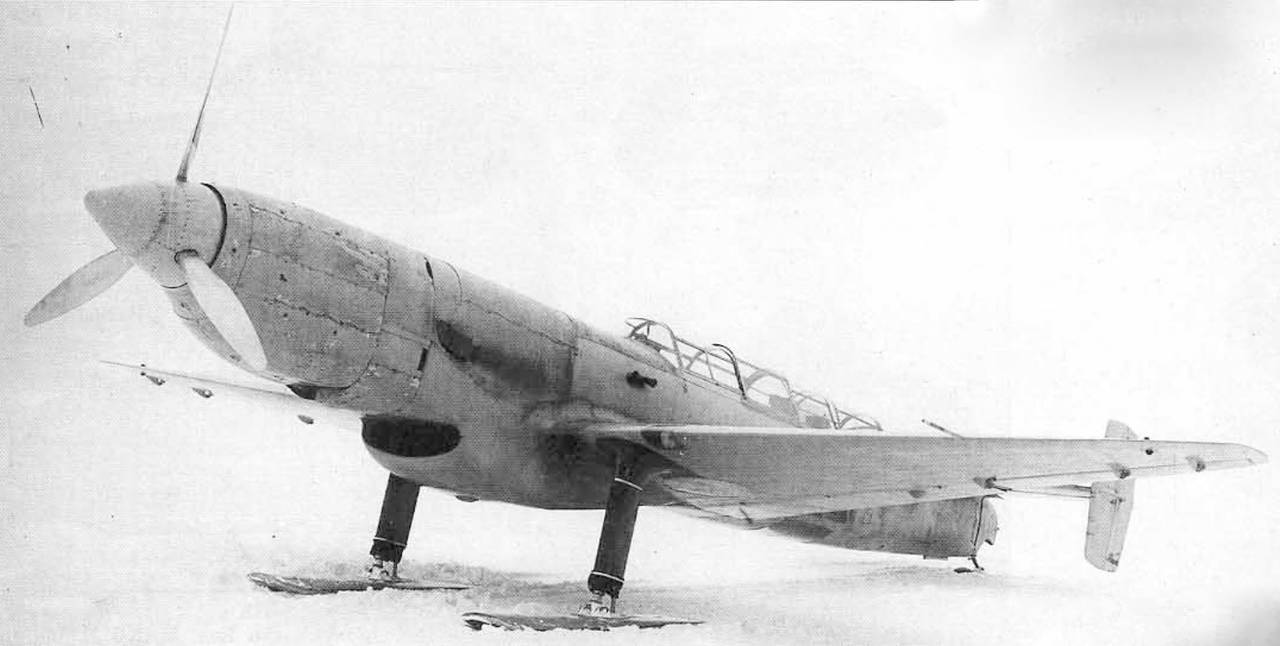
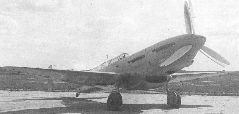
Aircraft C-1 before testing. General form. January 1940
Home stories It refers to 1933, the period of discussion of the design options for the fighter JNUMX. In particular, at the meeting with the head of the Air Force Ya. I. Alksnis in December 17, among others, the project of the two-seat I-1933, defined as DI-17, was considered. Due to doubts about its need, specific decisions on such a two-seat vehicle have not been made for a long time. At some stage in the development of events, the option of installing two twin engines on the DI-7, one after another rotating two propellers in opposite directions, arose. With respect to such a motor installation, the definition of “mechanical Spark” was used. Interest in this topic at the beginning of 7 intensified in connection with the deployment of design work to create a record high-speed aircraft. As a result, the motor plant No. 1935 was given the task of developing a “mechanical pairing” of M-26 engines (then M-100).
In the form of a small digression, it makes sense to devote some space to describing the very problem of articulated engines. It is clear that the connection of two engines one after the other into a single power unit made it possible, first of all, to significantly reduce aerodynamic drag. In addition, the studies carried out, and simply elementary considerations, suggested to designers the idea of the advantages of propellers assembled on the same axis and rotating in opposite directions. The total reactive moment of such screws was zero, as a result of which there was no need for aerodynamic compensators. In a curved flight, for example, a bend, the gyroscopic moment of each individual propeller was eliminated, which increased the maneuverability of the aircraft. Then - the air flow, twisted by the front screw, was straightened by the rear screw, which created the possibility of increasing the efficiency of the entire propeller group. Moreover, the rectified flow provided a symmetrical flow around the aircraft itself, which favored the improvement of its controllability during takeoff and landing.
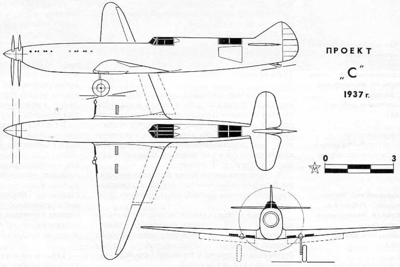
The project of the aircraft "C". Approved 1937
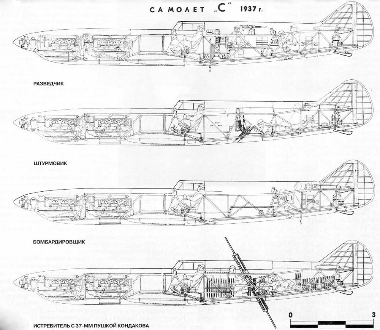
Variants of the aircraft "C" on the project 1937.
These theoretical considerations required practical evidence. And such evidence appeared very soon. For the first time, the extraordinary capabilities of articulated engines and coaxial propellers were demonstrated in triumphal fashion by the Italian record seaplane Mackey - Castoldi M-72 (Macchi MC72).
This aircraft was built specifically for participation in popular international competitions for the Schneider Cup, where world flight speed records were often set. The peculiarity of the competitions was the performance of exclusively seaplanes on them, and the vast majority of them were double-float machines. The pilots participating in this international championship had to start taking off at right angles to the wind, as the unbalanced jet moment of a single propeller forced one of the floats to completely submerge, resulting in an almost full turn of 90 ° to the wind direction at the start. The described maneuver was forced, complicated in execution and presented a considerable danger. Obviously, this flaw was one of the motivations that led designer Mario Castoldi to use twin engines and coaxial screws on his M-72. Conducted in the process of creating a seaplane studies have shown that we can expect a significant increase in speed. And although the rotation of the screws on the M-72 was not synchronized (each screw was rotated from a separate engine, so they always had some difference in speed), success was achieved. In the summer of 1934, the Italian M-72 set a world speed record of 709 km / h, which lasted until 1939.
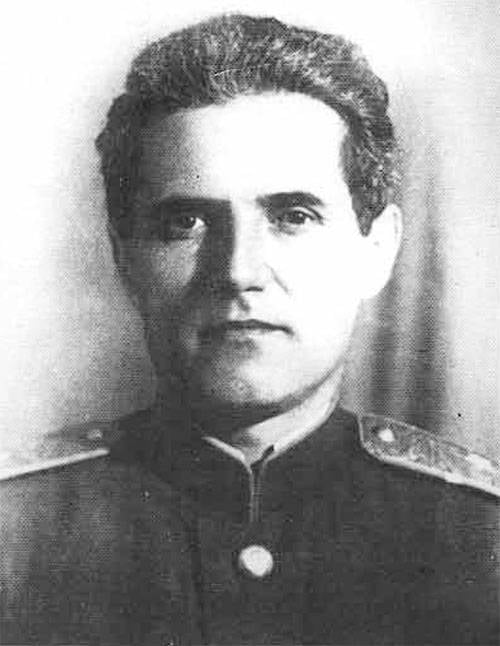
Viktor Fedorovich Bolkhovitinov
But back to the description of the problems and achievements of the Soviet aviation. The final task for the manufacture of a “mechanical coupler” appeared after the development of licensed Ispano Suiza engine engines in Rybinsk, and the beginning of their production under the Soviet designation M-26. At first they experimented with these engines, then switched to the more powerful M-100. In both cases, the so-called cannon engines were used - the engine shaft in them was made hollow for installing a rapid-firing gun.
So, two M-103P engines were installed on the same rigid engine mount. The rear engine shaft passed through the front hollow shaft and rotated the front propeller. And the front engine rotated the rear propeller. Tests of such pairing of M-103P engines at the stand were carried out in 1936 with quite encouraging results. It was decided to build a plane for the installation, and Bolkhovitinov got the order for it.

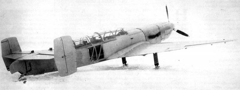
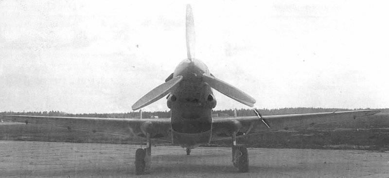
Aircraft C-1 before flight tests. January 1940.
Military engineer 1 rank Viktor Fedorovich Bolkhovitinov in 1937 was the chief designer of the Kazan Aviation Plant No. 124, where they laid a series of DB-A. bombers. With the receipt of a new and very interesting task, many ideas on technology and armament immediately appeared. That is why the designer's proposals were initially expressed in the form of a preliminary draft submitted to 23 on November 1937 for consideration. In total, four versions of the aircraft were proposed:
1. Scout with a range of up to 2200 km.
2. Middle bomber.
3. An attack aircraft, armed with ten ShKAS machine guns. (After consulting with the designers Mozharovsky and Venevidov, the weapons and methods of attack of the target changed. These gunsmiths suggested using twin machine guns UltraShKAS with a rate of fire of 10000 shots per minute. Machine guns mounted on the swinging node allowed to cover with fire a strip of ground 25 m wide).
4. "Bomber" fighter (BI) with 37 – mm gun designed by Kondakov to fight enemy bombers. The gun had two barrels firing for mutual destruction of recoil simultaneously in opposite directions. Shooting from one barrel was carried out by shells, from the other - by weight blanks. The firing range of the 37 – mm gun was 4 km, and the charging and gunner were on board the aircraft for its maintenance.
During the discussions and revisions of the project, the Bolkhovitinov aircraft turned into a double high-speed bomber with defensive armament in the form of a single ShKAS machine gun. For effective protection of the tail section, the vertical tail was made separated. Offensive armament was supposed to be two ShKAS in the wings (or under the wings), but never installed.
The high-speed bomber “C” was designed according to the TTN Air Force 1937 g. According to these requirements, the maximum speed of the aircraft was 640 km / h. However, theoretical calculations promised even more - 668 km / h at an altitude of 5250 m. There were grounds for optimism: the plane had a long, elongated fuselage, a small wing and a small area with a new, high-speed BBS profile. To reduce the landing speed, special retractable flaps, the so-called “Fowler type” flaps, were used. In general, the design used the most progressive, the fuselage was assembled from four carefully made and well-joined panels - the top, bottom and two side. The wing had a smooth trim; it had reinforcements in the form of a reinforcing inner corrugation.
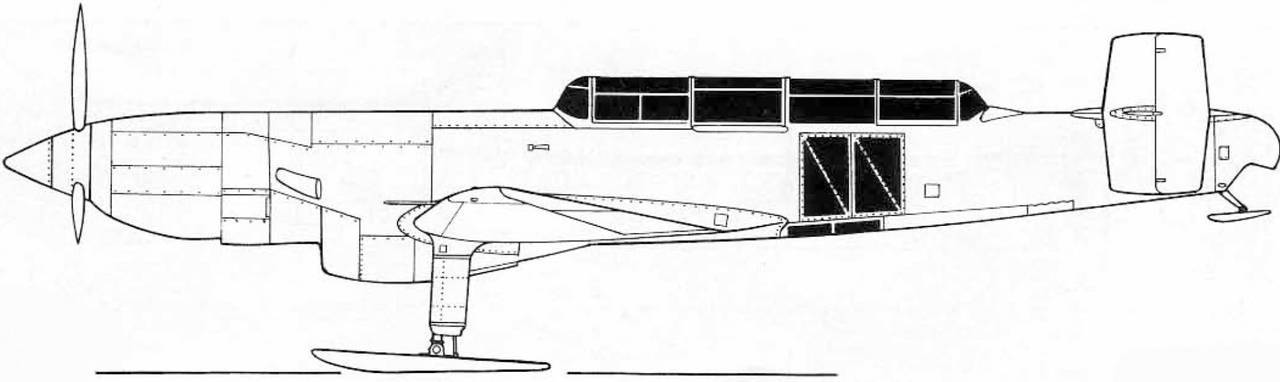
Aircraft C-1 side view. Scale 1: 72.
The model of the aircraft was considered 16 June 1938 in Kazan - at the place of the main location of the main designer Bolkhovitinov. However, Viktor Fedorovich was soon able to achieve a transfer to Moscow - the design bureau was relocated in August – September 1938. Those who arrived in the Fotolet workshops in the territory of Plant No. 84 were accommodated, and the organization itself soon became known as Aviation Plant No. 293.
In a special government decree concerning the design and construction of a new aircraft, the first instance of a nearby high-speed bomber (BBS) was to be tested in August 1939, the second copy - in December 1939.
The direct performers of the assignment, the chief designer Bolkhovitinov and the director of the plant No. 84 Yarunin, had to fulfill the following requirements for the aircraft:
The aircraft’s weaponization was indicated: a ShKAS machine gun in the upper defensive installation and 4 bomb cartridges AK-1М in the fuselage to accommodate four 100 – kilogram bombs.
In accordance with the accepted deadlines for the Bolkhovitinov aircraft, aircraft plant No. 26 (represented by director Balandin and chief designer Klimov) was to deliver to plant No. 84 the first “pair” of M-103 engines to 5 June 1939, following June 10, two more 1 August 1939
In total, under the designation "C" built two experimental apparatus: C-1 and C-2. The first C-1 was prepared in the second half of 1939. It was equipped with one M-103 engine with a VISH-2 propeller. The purpose of the C-1 test was to assess its flight performance - stability, controllability and take-off and landing characteristics. In addition, it was necessary to evaluate the systems and equipment, determine the internal and external pressures on the engine hood to allow the second car to reach maximum flight speeds.
C-1 entered the tests at the end of 1939. The Armament did not have any special equipment, it was installed on a non-removable ski landing gear. His first flight took place on 26 in January 1940, the pilot B. Kudrin flew. In total, before the end of tests in March, 1940 managed to perform 29 flights, the maximum speed of 400 km / h was reached. In addition to Kudrin, the pilot Kabanov participated in the flights from the Scientific Research Institute of the Air Force, so the tests were counted as joint - factory and state. The flight assessment was quite acceptable, there were practically no defects identified during the testing process, and there were no routine modifications.
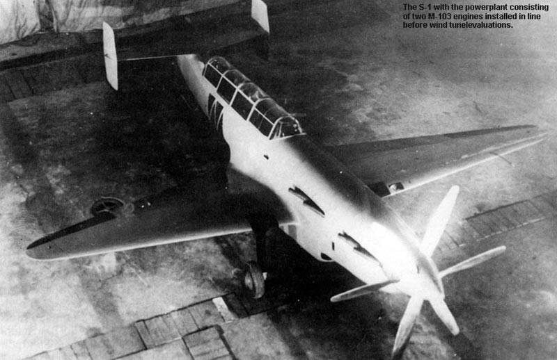
C-1, equipped with an M-103 with a developed resource before blowing in a wind tunnel, 1940.
It was admitted that C-1 is in all respects fully aircraft driven; piloting techniques are available to medium-skilled pilots. The obtained test results of this machine made it possible to boldly embark on flights of the twin-engine C-2 variant. In the conclusion of the C-1 report, it was said: “To consider it necessary, without waiting for the end of the test of the aircraft No. 2, to start preparing the drawing facilities for building an experimental series of aircraft”.
Later, at the first experimental C-1, the M-103 twin engines were installed using the engine life, and the aircraft in this design was used for full-scale studies in the TsAGI wind tunnels.
Even before the end of testing the first machine from 20 in March 1940, the flights of the second experienced C-2 began. The goal was specific: “To verify the compliance of the actual flight data of the aircraft and its armament with the tactical and technical requirements and assess the possibility of adopting this aircraft for the Air Force.” The very formulation of the task itself indicated that the second machine was fully equipped and armed. In the space between the cockpit of the pilot and navigator was a bomb bay that accommodates 4 FAB-100. The loading of bombs took place through the opening fragment of the cockpit canopy using a special crane - beam. In addition to the indicated internal placement of the aerial bombs, a suspension of four FAB-100s on the outer holders under the wing was assumed.

"Mechanical Spark" M-103 motors.
The navigator's cockpit had glazing in the floor and on the sides to improve the view, it was equipped with all the main navigation instruments, sight, bomb rammer, RSB radio station. Immediately behind the navigator’s cabin was the AFA-1 camera. The crew cabin bookings did not have.
The C-2 was equipped with two twin M-103P engines, each with an 960 power. with. at a height of 4000 m, with propellers - automata VISH - KB Air Force. The exhaust pipes of jet-type engines, they were made in the form of welded manifolds, combining exhaust from three cylinders. The gas tanks are unprotected, with a total capacity of 660 l, in the amount of three tanks placed in the fuselage, immediately behind the engines. Water cooling radiators for both engines were placed in a single unit under the fuselage. Here, in the same tunnel with water radiators, there were two cylindrical 8 – inch oil radiators. The back of all this “beard”, prominently protruding from the aircraft, was equipped with a single movable door to adjust the cooling of all radiators.
Supplement the brief description of the aircraft should be some details regarding the features of its device. The wing was connected to the fuselage by four knots, called a caisson type design, its socks and tails were detachable throughout their span, attached to the central part by ramrods. The tail stabilizer is mobile, its shift control could be carried out in flight using a steering wheel from the cockpit. The design of the tail assembly is similar to that of the wing.
State tests of the second “C” aircraft, which began immediately after the first flights, continued until July 25 1940. They flew: the pilot of the Air Force Research Institute, Colonel A. I. Kabanov, and the navigator P. I. Nikitin. In flight, this crew reached a maximum speed of 570 km / h at the calculated altitude.
The flight assessment of the C-2 was generally positive, and it was recognized that piloting control was simple and fairly easy. The plane was well listened to the rudders on all flight modes, up to maximum speed, planning, climb and turns. However, the high specific load on the wing (on the first machine was 171 kg / m2, on the second, due to increased flight weight, it was 246 kg / m2) sharply worsened the takeoff and landing characteristics of the aircraft. After breaking off at a speed of 200 km / h, he then slowly accelerated to the most favorable climb rate of 300 – 310 km / h. The forest surrounding the NII VVS airfield was at a distance of 2 km from the launch site, but the plane literally passed over the treetops when it took off. Attempts to use the Fowler flaps as efficiently as possible, which were supposed to increase the wing carrying capabilities and reduce the flight speeds of the aircraft, did not produce any tangible positive results, and they were abandoned.
Landing was no less difficult. C-2 planned with fully open flaps at a speed of 240 km / h, landing quickly lost speed and became unstable. According to testers' testimonies, the complex takeoff and landing qualities of the new aircraft made it available only to highly qualified pilots. An additional drawback was considered his too long nose, making it difficult for the pilot to get an overview when entering the target. At the navigator, the downward view was hampered by the fact that the glazing was sprayed with oil, covered with dust and dirt during takeoff. The loading of bombs through the opening canopy turned out to be inconvenient.


Aircraft C-2 before flight tests. Spring 1940.
According to the test results of the C-2, it was recognized that the maximum speed reached by 570 km / h was lower than that required by 70 km / h, and the landing speed 165 – 168 km / h was too high, the flight range was lower than stated: 700 km instead of 1200 km according to the Committee’s decision Defense Although for all the above reasons, the C plane failed to withstand state tests, it was also noted: “... the C plane is an experimental aircraft that was the first in the Union to solve the problem of increasing the power of the propeller group without increasing drag, and this task was almost solved by the designer . The combination of two engines in one unit with success can be used on fighter aircraft with pushing screws and on the bombers of a normal twin-engine scheme. Considering the availability of a maximum speed of 570 km / h at an altitude of 4600 m and the possibility of raising it, as well as the possibility of eliminating defects for which the aircraft could not withstand state tests, the Red Army Air Force Institute considers it necessary to first improve takeoff and landing properties and then re-show aircraft for control tests at the Scientific Research Institute of the Air Force for February 1 1941.
Consider it necessary to carry out the following work in TsAGI and CIAM:
1. Identify the characteristics of coaxial screws.
2. Reveal the best working conditions for twin motors on one common motor mount. ”
Thus, the design, construction and testing of aircraft "C" was recognized as a positive fact. The characteristics of the aircraft recorded on the tests in comparison with the design values are given below.
The history of aircraft with twin engines and coaxial propellers could have continued. Suffice it to say that the very idea of such a power plant has already received noticeable distribution and was viewed with interest by many designers. One of the first, back in 1934, was to use it in his flying Sigma triangle, designer Alexander Moskalev, who in 1940 used the coaxial propellers in the design of the flying boat CAM-19. The “mechanical Spark” of the M-105 engines was a key element in the project of the four-engined fighter Konstantin Tairov OKO-9, Alexander Arkhangelsky was counting on the use of coaxial propellers in the design of his own aircraft, the “T” attack aircraft.
Even before the C-2, 15 tests of February, 1940, the aircraft designer G. M. Beriev, specializing in the development of hydroplanes, turned to the People's Commissariat of the aircraft industry with his project of a high-speed aircraft B-10. In the presented draft design, the B-10 was defined as a fighter - an interceptor or a dive bomber. Performed according to the two-girder nizkoplan scheme, the plane carried a lot of original proposals: a three-wheeled chassis with a nose support, a NACA 23012 wing with a laminar profile, twin M-107 engines with pushing coaxial four-bladed propellers. According to the calculations made in the Beriev KB, the new B-10 could provide the maximum flight speed of up to 818 km / h.
Fowler-type flaps on the C-1.

Lanterns of the cockpit of the pilot and navigator of the C-2 aircraft in a semi-shifted position for landing / flight from hell to the crew.
The remaining design characteristics of the B-10 were as follows:
Project B-10 was considered in the General Directorate of Aviation Supply of the Red Army (GUAS KA). In conclusion, it said that the aircraft is quite real and its development can be included in the 1941 plan. However, due to the heavy workload of the Beriev Design Bureau by developing promising hydroplanes, the work on B-10 was proposed to be entrusted to Bolkhovitinov, since he already specializes in such topics.
Demonstration of loading bomb load in the middle combat compartment of the C-2. 1940
In accordance with the government’s decision of 18 in March 1940, the further work on the B-10 was entrusted to Bolkhovitinov, the designation “I” was assigned to his design bureau. Designer A. M. Isaev was assigned to lead the aircraft.
The sketch project “I” was submitted to the NCAA Expert Commission and approved by it 21 September 1940. On the whole, the project was reminiscent of the Berium B-10, but the engines were assumed to be M-105 (as more real), the wing area was reduced to 20 square. m, the maximum speed was assumed 675 km / h. In the future, the developers still focused on the M-107, the task of creating his “Sparky” was entrusted to the Rybinsk Motor Plant.
The development of the project “I” was carried out until the spring of 1941, mainly the construction and technological methods used on the “C” aircraft were used. At the same time, there were many new things. In particular, they used a wing - a fuel tank made of an electron, with a skin thickness of up to 4 mm. The technology of production of the electron itself, methods of manufacturing parts from it, and much more, were mastered.
The plane was already started building, but soon followed a series of government decisions on the folding of a number of experimental and experimental developments. The decision to stop the production of a fighter - bomber with twin M-107 engines designed by Bolkhovitinov was followed by an 21 in March 1941.
It was already mentioned above that 25 on April 1941 of Bolkhovitinov was summoned to meet with the Deputy Commissar of Aviation Industry for Engine Building Balandin. Attended by plant manager number 26 Lavrentiev and engine designer Klimov. The reason for the call was the engine's refusal to create the M-107 mechanical sparks. In their opinion, the creation of such a power plant in the foreseeable future seemed unrealistic. M-107 was very “raw” and uncompleted, it was believed that when installing an elongated shaft at working revolutions dangerous resonant phenomena would occur that could lead to the destruction of the structure.
In fact, the engine has received many recommendations to reduce the original development, with a long-term perspective. In addition, the motor plant in Rybinsk had a very large plan for the production of serial products, here continued the complex and painstaking refinement of the serial M-105, experienced M-107 and M-120.
As a “sweet pill,” Bolkhovitinov was offered to choose any other domestic engine and rework his project for it. Diesel M-40 was chosen, under which, in particular, the heavy D-bomber was designed. An attempt to adapt a diesel engine to the project “I” seemed to be ineffective. However, it was possible to return to the proven scheme of the aircraft "C", but in a single-engine version. In his letter to the government, Bolkhovitinov wrote: “... I ask you to charge me instead of an“ I ”plane ... a single-engined plane, with an M-40, on the basis of a previously built machine“ C ”, giving it weaponshooting through the propeller according to the wishes of I. V. Stalin (it is said that Stalin, having examined "C", demanded that the aircraft be fired forward through the propeller's rotation disk. - M. М.) ".
In the autumn of 1941, the KB-293 of V. F. Bolkhovitinov was evacuated to the Urals, where the epic on the improvement of the BI rocket plane began. None of the projects of the pre-war bombers was brought to a logical conclusion.
The main characteristics of the aircraft "C"
| Name | Full length, m | Wingspan, m | Wing area, m2 | Flight weight, kg | Wing loading kg / m2 | Max speed km / h |
| Project | 13,05 | 11,4 | 23,1 | - | - | 640 |
| C-1 | 12,816 | 12,21 | 23,428 | 4000 | 171 | 400 |
| C-2 | 12,816 | 11,30 | 22,9 | 5652 | 246 | 570 |
Information