The family of two-stroke diesel engines of Soviet armored vehicles
In 1955, a government decision was made to establish a special diesel engine engineering design bureau at the Kharkiv transport engineering plant and to create a new tank diesel engine. Professor A.D. Charomsky was appointed the chief designer of the design bureau.
The choice of the constructive scheme of the future diesel engine was determined mainly by the experience of working on 2-stroke diesel engines OND TsIAM and the U-305 engine, as well as the desire to most fully satisfy the requirements of the designers of the new tank T-64, developed at this plant under the leadership of the chief designer A.A. Morozov: to ensure the minimum dimensions of the diesel engine, especially in height, in combination with the possibility of placing it in the tank in the transverse position between the onboard planetary gearboxes. A 2-stroke diesel engine with a horizontal arrangement of five cylinders with pistons oppositely moving in them was selected. It was decided to perform an engine with inflation and energy recovery of exhaust gases in the turbine.
What is the reason for the choice of diesel, working on the 2-stroke cycle?
Earlier, in the 20s-30s, the creation of a 2-stroke diesel engine for aviation and land vehicles were restrained due to many unsolved problems that could not be overcome with the accumulated by that time level of knowledge, experience and capabilities of domestic industry.
The study and research of 2-stroke diesel engines of some foreign companies led to conclusions about the significant difficulty of mastering them in production. For example, the study of the Jumo-30 diesel engine by Hugo Yunekers in the 4-s of the Jumo-30 diesel engine at the Central Institute of Aviation Motors showed significant problems associated with the development of similar engines in the domestic industry of that period. It was also known that Britain and Japan, who had purchased a license for this diesel engine, suffered failures in mastering the production of the Junkers engine. At the same time, 40-s and 2-s in our country already conducted research work on 2-stroke diesel engines and produced experimental samples of such engines. The leading role in these works belonged to the specialists of CIAM and, in particular, to its Oil Engine Department (OND). In TsIAM, samples of 2-stroke diesel engines of various dimensions were designed and manufactured: OH-12 (16,3 / 16), OH-11 (14 / 17), OH-18 (20 / 4), OH-8 (9 / XNUMX / XNUMX / XNUMX), OH-XNUMX (XNUMX / XNUMX), OH-XNUMX (XNUMX / XNUMX) a number of other original engines.
Among them was the engine FED-8, designed under the guidance of prominent engine scientists B.S.Stechkin, N.R. Briling, A.A.Bessonova. It was a 2-stroke 16-cylinder X-shaped aviation diesel engine with valve-piston gas distribution, with the dimension 18 / 23, developing power 1470 kW (2000 hp). One of the representatives of 2-stroke supercharged diesel engines was a star-shaped 6-cylinder turbo-piston diesel engine manufactured in CIAM under the guidance of BSStechkin. 147 ... 220 kW (200 ... 300 hp). The power of the gas turbine was transferred to the crankshaft through the corresponding gearbox.
The decision taken at the time when the FED-8 engine was created was, at the time, a significant step forward in the very idea and design scheme. However, the working process and especially the process of gas exchange with a high degree of pressurization and loop purging were not pre-tested. Therefore, diesel FED-8 has not received further development and in the 1937 year, work on it was discontinued.
After the war, German technical documentation became the property of the USSR. She fall A.D. Charomsky, as a developer of aircraft engines, and he is interested in the “suitcase” of Junkers.
Junkers' “Suitcase” - a series of Jumo 205 two-stroke twin-stroke turbo-piston engines with opposing pistons was created in the early 30s of the twentieth century. The characteristics of the engine Jumo 205-C are as follows: 6-cylinder, power 600 hp piston stroke 2 x 160 mm, l. volume 16.62., compression ratio 17: 1, at 2.200 rpm.
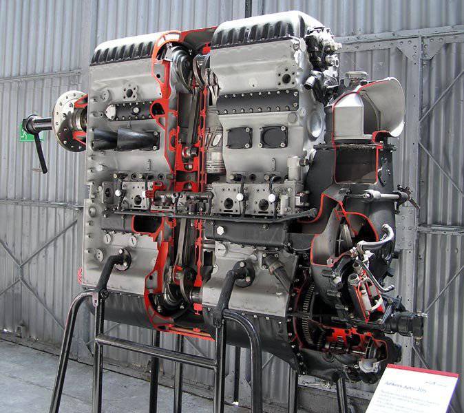
Jumo 205 Engine
During the war years, about 900 engines were produced, which were successfully used on Pre-18, Pre-27 seaplanes, and later on speedboats. Soon after the end of the Second World War in 1949, it was decided to install such engines on the East German patrol boats that were in service before the 60-s.
On the basis of these developments by A.D. Charomsky, the two-stroke M-1947 aviation diesel engine and the single-cylinder compartment of this engine, the U-305 engine, were created in the USSR. This diesel engine developed 305 kW (7350 hp) with a small specific mass (10000 kg / hp) and low specific fuel consumption -0,5 g / kWh (190 g / hp.h). The X-shaped arrangement of the 140 cylinders (four 28-cylinder blocks) was adopted. The dimension of the engine was chosen to be 7 / 12. High boost was carried out by a turbocharger, mechanically connected with the shaft of a diesel engine. To test the main characteristics of the M-12 project, to refine the workflow and design of the parts, an experimental model of the engine was built that had the index U-305. G.V. Orlova, N.I.Rudakov, L.V.Ustinova, N.S.Zolotarev, S.M. Shifrin, N.S. Sobolev, as well as technologists took an active part in the design, development and testing of this diesel engine. and workers of the pilot plant CIAM and workshop of the UNM.
The project of the full-size M-305 aircraft diesel was not implemented, since the work of CIAM, like the entire aviation industry of the country, was already focused on the development of turbojet and turboprop engines and the need for 10000-strong diesel for aviation disappeared.
The high performance obtained on the U-305 diesel engine: liter power of an 99 engine kW / l (135l.s./l), liter power from one cylinder is almost 220 kW (300l.s.) at a boost pressure of 0,35 MPa; The high rotational speed (3500 rpm) and the data of a number of successful long engine tests confirmed the possibility of creating an efficient small-sized 2-stroke diesel for transportation purposes with similar indicators and structural elements.
In 1952, Laboratory No. 7 (former OND) of CIAM with a governmental decision was transformed into the Engine Research Laboratory (NILD) under the authority of the Ministry of Transport Engineering. The initiative group of employees - highly qualified specialists in diesel engines (G.V. Orlova, N.I. Rudakov, S.M. Shifrin, and others), headed by Professor A.D. Charomsky, as part of NILD (later NIID) continue to work on fine-tuning and research of the 2-stroke engine U-305.
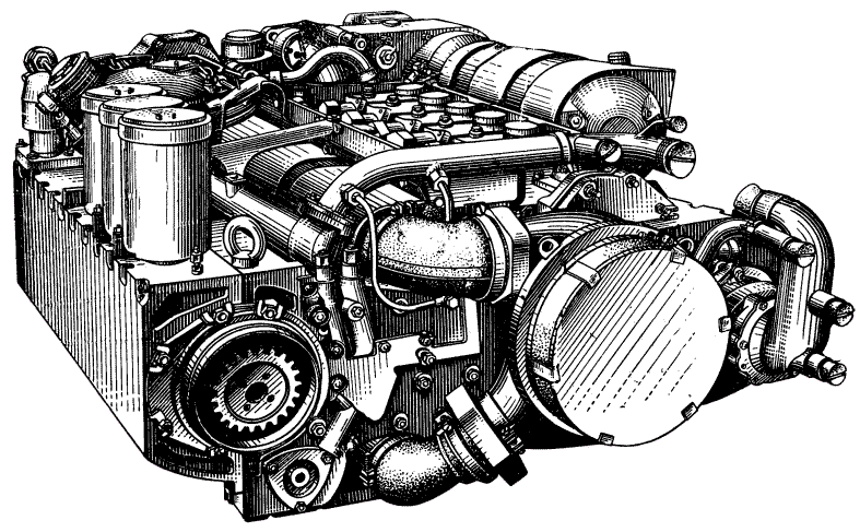
Diesel 5TDF
In 1954, A.D. Charomsky a proposal was made to the government to create an 2-stroke tank diesel. This proposal coincided with the demand of the chief designer of the new tank A.A. Morozova, and A.D. Charomsky was appointed chief designer of the plant. V. Malysheva in Kharkov.
Since the tank motor design bureau of this plant remained mainly in Chelyabinsk, then A.D. Charomsky had to form a new design bureau, create an experimental base, establish experimental and mass production, and work on developing a technology that the plant did not have. Work began with the manufacture of single-cylinder installation (OTSU), similar to the engine U-305. At the OTU, the elements and processes of the future full-sized tank diesel engine were developed.
The main participants of these works were A.D. Charomsky, G.A. Volkov, L.L.Golinets, B.M. Kugel, M.A., Meksin, I.L. Rovensky and others.
In 1955, the NILD employees: G.V. Orlova, N.I. Rudakov, V.G. Lavrov, I.S. Elperin, I.K.Lagovsky, and others. The NILD specialist L. M. Belinsky, L. I. Pugachev, L. S. Roninson, S. M. Shifrin carried out experimental work at OTSU at the Kharkov Transport Engineering Plant. So there is a Soviet 4TPD. It was a working engine, but with one drawback - the power was just over 400 hp, which was not enough for the tank. Charomsky puts another cylinder and gets 5TD.
The introduction of an additional cylinder seriously changed the dynamics of the engine. There was an imbalance that caused intense torsional vibrations in the system. The leading scientific forces of Leningrad (VNII-100), Moscow (NIID) and Kharkov (KPI) are connected to its solution. 5TDF was brought up to standard EXPERIMENTAL by trial and error.
The dimension of this engine was chosen to be 12 / 12, i.e. the same as on the engine Y-305 and OCU. To improve the injectivity of the diesel engine, it was decided to mechanically connect the turbine and the compressor to the crankshaft.
The 5TD diesel engine had the following features:
- high power - 426 kW (580 hp) with relatively small overall dimensions;
- Increased speed - 3000 r / min;
- efficiency of pressurization and energy utilization of waste gases;
- low height (less than 700 mm);
- a decrease in 30-35% heat transfer compared with existing 4-stroke (naturally aspirated) diesel engines, and hence the smaller volume required for the cooling system of the power plant;
- satisfactory fuel efficiency and the ability to operate the engine not only on diesel fuel, but also on kerosene, gasoline, and their various mixtures;
- power take-off from both its ends and its relatively small length, which makes it possible to assemble the MTO tank with a transverse diesel arrangement between two onboard gearboxes in a much smaller occupied volume than with a longitudinal engine and central gearbox;
- successful placement of such units as high-pressure air compressor with their systems, starter-generator, etc.
Retaining the transverse arrangement of the motor with a two-sided power take-off and two planetary onboard transmissions located on both sides of the engine, the designers shifted the vacant sides of the engine, parallel to the gearboxes, compressor and gas turbine, previously installed in 4ТD on top of the engine block. The new layout allowed halving the amount of logistic equipment in comparison with the T-54 tank, and traditional components such as the central gearbox, gearbox, main friction clutch, onboard planetary steering mechanisms, onboard gears and brakes were excluded from it. As noted later in the report of the GBTU, the transmission of a new type saved 750 kg of mass and consisted of 150 machined parts instead of the previous 500.
All engine maintenance systems were interlocked above the diesel engine, forming the “second floor” of the logistic service, the scheme of which received the name “two-tier”.
The high performance of the 5TD engine required the use in its design of a number of new fundamental solutions and special materials. The piston for this diesel engine, for example, was manufactured using a heat pad and spacer.
As the first piston ring, a continuous hot ring was used. The cylinders were made of steel, chrome.
The ability of the engine to operate with a high flash pressure was provided by the power circuit of the engine with bearing steel bolts, cast aluminum block, unloaded from the action of gas forces, as well as the absence of a gas joint. Improving the process of purging and filling the cylinders (and this is a problem for all 2-stroke diesel engines) contributed to a certain extent to the gas-dynamic scheme using the kinetic energy of exhaust gases and the ejection effect.
The jet-vortex mixing system, in which the nature and direction of the fuel jets are consistent with the direction of air movement, ensured effective turbulization of the fuel-air mixture, which contributed to the improvement of the process of heat and mass transfer.
Specially selected form of the combustion chamber also allowed to improve the process of mixing and combustion. The main bearing caps were tightened with a block-case of steel power bolts perceiving the load from the gas forces acting on the piston.
A stove with a turbine and a water pump was attached to one end of the crankcase, while the main gear and covers with the drives were attached to the opposite end of the crankcase to the supercharger, regulator, tachometer sensor, high-pressure compressor and air distributor.
In January 1957, the first prototype of a tank diesel 5TD was prepared for bench tests. At the end of the bench tests 5TD in the same year was transferred to object (running) tests in an experimental tank "object 430", and by May 1958 passed interdepartmental State tests with a good rating.
Nevertheless, it was decided not to transfer the diesel 5TD to mass production. The reason once again was the change in military requirements for new tanks, once again necessitating a rise in power. Taking into account the very high technical and economic performance of the 5TD engine and the reserves built into it (as demonstrated by the tests), the new powerplant with an output of about 700 hp. decided to create based on it.
The creation of such an original for the Kharkov plant of transport engineering of the engine required the manufacture of significantly technological equipment, a large number of prototypes of diesel and long-term repeated tests. It should be borne in mind that the design department of the plant - subsequently Kharkov Design Bureau of Mechanical Engineering (HKBD), and the motor production were created after the war almost anew.
Simultaneously with the design of a diesel engine, a large complex of experimental stands and various installations (24 units) was created at the plant to work out the elements of its design and workflow. This greatly helped to check and work out the design of such components as a supercharger, turbine, fuel pump, exhaust manifold, centrifuge, water and oil pumps, crankcase, etc. By the time the first diesel engine was assembled, these elements were already pre-tested on the stands however, their development continued.
In 1959, at the request of the chief designer of the new tank (A.A. Morozov), for which this diesel engine was designed, it was considered necessary to increase its power from 426 kW (580 hp) to 515 kW (700л.с. ). The forced version of the engine received the name 5TDF.
By increasing the frequency of rotation of the supercharger compressor was increased liter engine power. However, as a result of forcing a diesel engine, new problems appeared, primarily on the reliability of components and assemblies.
Designers of HKBD, NIID, VNIItransmash, technologists of the plant and institutes of VNITI and TsNITI (from 1965) carried out a huge amount of design, research, design and technological work to achieve the required reliability and performance of the 5TDF diesel.
The most difficult was the problem of improving the reliability of the piston group, fuel equipment, turbocharger. Each, even a slight improvement was given only as a result of the whole complex of design, technological, organizational (production) measures.
The first batch of diesel engines 5TDF was characterized by high instability in the quality of manufacturing parts and components. A certain part of the diesel engines of the series (batch) produced gained the established warranty time (300). At the same time, a significant part of the engines was removed from the stands up to the warranty period because of certain defects.
The specificity of a high-speed 2-stroke diesel engine consists in a more complex gas exchange system than in an 4-stroke, increased air consumption, and a higher thermal load of the piston group. Therefore, rigidity and vibration resistance of the structure, more strict adherence to the geometrical shape of a number of parts, high anti-creep properties and cylinder wear resistance, heat resistance and mechanical strength of the pistons, metered supply and removal of cylinder lubrication and improving the quality of rubbing surfaces were required. To take into account these specific features of 2-stroke engines, it was necessary to solve complex design and technological problems.
One of the most important parts, providing a clear gas distribution and protection of the sealing piston rings from overheating, was a rifled steel thin-walled ring-type hot ring with a special anti-friction coating. In the debugging of the 5TDF diesel, the problem of the performance of this ring has become one of the main ones. In the process of fine-tuning for a long time there were tears and breakage of the heat rings due to the deformation of their support plane, non-optimal configuration of both the ring itself and the piston body, unsatisfactory chrome-plating of the rings, insufficient lubrication, uneven fuel supply by the nozzles, scaling of scale and deposition of salts formed on the piston cover, as well as due to dust wear due to insufficient cleaning of the engine intake air.
Only as a result of long and hard work of many specialists of the plant and research and technological institutes, as the configuration of the piston and the firing ring improves, the manufacturing technology is improved, the elements of the fuel equipment are improved, lubrication is improved, the use of more efficient anti-friction coatings and the air cleaning system are improved. defects associated with the operation of the flame ring were practically eliminated.
Breakage of trapezoidal piston rings, for example, were eliminated by reducing the axial clearance between the ring and the piston groove, improving the material, changing the cross-sectional configuration of the ring (shifted from the trapezoid to the rectangular one), and refining the technology for manufacturing rings. Breakage of bolts securing the piston linings were eliminated by changing the thread and locking, tightening control in production, limiting the tightening force and using improved bolt material.
The stability of oil consumption was achieved by increasing the stiffness of the cylinders, reducing the size of the cutouts at the ends of the cylinders, tightening control in the manufacture of oil gathering rings.
By fine-tuning the elements of the fuel apparatus and improving gas exchange, some improvement in fuel efficiency and a decrease in the maximum flash pressure were obtained.
By improving the quality of the used rubber and the ordering of the gap between the cylinder and the block, cases of coolant leakage through the rubber sealing rings were eliminated.
Due to a significant increase in the gear ratio from the crankshaft to the supercharger, on some 5TDF diesel engines such defects as slipping and wear of the friction clutch discs, failures of the supercharger wheel and the failure of its bearings, which were absent on the 5TD diesel, were identified. To eliminate them, we had to carry out such activities as selecting the optimal tightening of the package of the friction clutch discs, increasing the number of discs in the package, eliminating the voltage concentrators in the impeller of the supercharger, vibrating wheel, increasing the damping properties of the bearing, selecting higher quality bearings. This made it possible to eliminate the defects resulting from the forcing of diesel in terms of power.
Improving the reliability and performance of 5TDF diesel greatly contributed to the use of higher-quality oils with special additives.
On the stands of VNIItransmash with the participation of the HKBD and NIID employees, a large amount of research was done on the operation of the 5TDF diesel engine in real dust conditions of the intake air. They ended up with successful “dust” engine tests during the 500 hours of its operation. This was confirmed by the high degree of development of the cylinder-piston group of the diesel engine and the air cleaning system.
In parallel with the fine-tuning of the diesel itself, it was repeatedly tested in conjunction with the power plant systems. At the same time, the systems were being improved, the issue of their interconnection and reliable operation in the tank was being resolved.
In the decisive period of finishing the 5TDF diesel engine, LL Golinets was the chief designer of the KDKBD. Former Chief Designer A.D. Charomsky was retired, continued to take part in fine-tuning as a consultant.
Mastering the mass production of the 5TDF diesel engine in the new, purpose-built workshops of the plant, with new cadres of workers and engineers who studied on this engine, caused many difficulties, required a significant increase in the technical level in equipment of production, a lot of labor of many teams of factory services and workshops, significant participation of specialists from other organizations.
Until 1965, the 5TDF engine was produced in separate batches (batches). Each subsequent series included a number of measures developed and tested on the stands, eliminating defects found during the test and during trial operation in the army.
However, the actual operating time of the engines did not exceed 100 hours.
A significant change in the reliability of the diesel engine occurred at the beginning of the 1965 of the year. By this time, a large amount of changes was made to the design and technology of its manufacture. Introduced into production, these changes will increase the operating time of the next series of engines to 300 hours. The long running tests of tanks with engines of this series carried out confirmed the significantly increased reliability of diesel engines: all of the engines during these tests worked 300 hours, and some of them (selectively), continuing tests, worked on 400 ... 500 hours.
In 1965, the installation batch of diesel engines was finally released according to the corrected technical drawing documentation and technology for mass production. A total of 1965 production engines were manufactured in 200. Began to increase the release, peaking in 1980 year. In September 1966, the 5TDF diesel engine passed interdepartmental tests.
Considering history creating a diesel 5TDF, it should be noted the progress of its technological development as an engine completely new to the production of the plant. Almost simultaneously with the manufacture of prototypes of the engine and its design refinement, its technological development and the construction of new production facilities of the plant and their acquisition with equipment were carried out.
In accordance with the refined drawings of the first engine models, the development of design technology for the production of 1960TDF was started already in 5 year, and from the 1961 year they began to produce working process documentation. The design features of the 2-stroke diesel engine, the use of new materials, the high accuracy of its individual components, and the technology required the use of fundamentally new methods for processing and even engine assembly. The design of technological processes and their equipment was carried out both by the technological services of the plant, headed by A.I. Isaev, V.D. Dyachenko, V. I. Doshchechkin and others, and by employees of the technological institutes of the industry. Specialists of the Central Research Institute of Materials (director F.А. Kupriyanov) were involved in solving many metallurgical and materials science problems.
The construction of new workshops for the motor production of the Kharkov Transport Engineering Plant was carried out according to the project of the Soyuzmashproekt Institute (chief engineer of the project S. Shpynov).
During the 1964-1967. New diesel production was completed with the equipment (especially with special machines - more than 100 units), without which it would be practically impossible to organize the serial production of diesel engine parts. These were diamond-drilling and multi-spindle machines for processing the block, special turning and finishing machines for processing crankshafts, etc. Prior to the introduction of new workshops and testing sites and debugging of the manufacturing technology of a number of main parts, as well as the manufacture of installation batches and the first engine series were temporarily organized production sites of large diesel diesel engines.
The main capacities of the new diesel production were commissioned alternately during the 1964-1967 period. In the new workshops, the full cycle of production of 5TDF diesel engines was provided, except for blanking production, located on the main site of the plant.
In the formation of new production facilities, great attention was paid to raising the level and organization of production. The manufacture of a diesel engine was organized according to the flow and group principle, taking into account the latest achievements of that period in this area. The most progressive means of mechanization and automation of machining parts and assemblies were used, which ensured the creation of a complex-mechanized production of the 5TDF diesel engine.
In the process of production formation, a large joint work was carried out by technologists and designers to improve the manufacturability of the diesel engine design, during which the technologists issued about six thousand proposals to HKBD, much of which was reflected in the design documentation of the engine.
According to the technical level, the new diesel production significantly exceeded the figures achieved by that time by the enterprises of the industry producing similar products. The ratio of the production processes of the diesel engine 5TDF reached a high value - 6,22. In 3 alone, more than 10 of thousands of technological processes were developed, more than 50 of thousands of tool names were designed and manufactured. In the manufacture of tooling and tools, in order to assist the plant named after Malyshev, a number of enterprises of the Kharkov Economic Council were involved.
In subsequent years (after 1965), already in the course of mass production of the 5TDF diesel engine, the technological services of the plant and CNITI carried out work to further improve the technologies in order to reduce labor intensity, improve the quality and reliability of the engine. Employees of TsNITI (Director Ya.A. Shifrin, Chief Engineer B.N. Surnin) during 1967-1970. More than 4500 technology proposals were developed, providing less labor for more than 530 standard hours and a significant reduction in scrap losses during production. At the same time, these events allowed more than twice reducing the number of fitting operations and selective connections of parts. The result of the introduction of the design and technological measures was a more reliable and high-quality engine operation in operation with a warranty time of 300 hours. But the work of the plant technologists and CNIT together with the designers of the CCDB continued. It was necessary to increase the operating time of the engine 5TDF 1,5 ... 2,0 times. This task is also solved. The 2-stroke tank diesel 5TDF was refined and mastered in production at the Kharkov Transport Engineering Plant.
The plant director O.Soich played a very significant role in organizing the production of the 5TDF diesel engine, as well as a number of industry leaders (D. F. Ustinov, E. P. Shkurko, I. F. Dmitriyev, and others), constantly monitored the progress of development and development of diesel production, as well as those who were directly involved in solving technical and organizational problems.
Systems of autonomous flare heating and oil injection allowed for the first time (in 1978) to ensure a cold start of a tank diesel engine at temperatures down to -20 degrees C (from 1984 to -25 degrees C). Later (in 1985), it became possible to carry out a cold start of a four-stroke diesel engine (B-84-1) on T-72 tanks using the UHV system (intake air heater), but only up to temperature -20 degrees C, and no more than twenty starts within the warranty resource.
The most important thing is that 5TDF has smoothly transferred to the new quality in diesel engines of the 6TD series (6TD-1 ... 6TD-4) with a power range of 1000-1500 hp. and surpassing in a number of basic parameters foreign analogues.
MOTOR OPERATION INFORMATION
Used maintenance materials
The main type of fuel to power the engine is fuel for high-speed diesel engines GOST 4749 — 73:
at an ambient temperature not lower than + 5 ° С - DL marks;
at ambient temperature from + 5 to —30 ° С - DZ brand;
at ambient temperature below -30 ° С - YES mark.
If necessary, it is allowed at ambient temperatures above + 50 ° C to use DZ fuel.
In addition to fuel for high-speed diesel engines, the engine can run on TC-1 GOST 10227 — 62 jet fuel or A-72 GOST 2084 — 67 motor gasoline, as well as mixtures of used fuels in any proportions.
For lubrication of the engine oil is used М16-ИХП-3 ТУ 001226 — 75. In the absence of this oil, the use of MT-16п oil is allowed.
When switching from one oil to another, the remaining oil from the crankcase of the engine and the oil tank of the machine must be drained.
Mixing used oils with each other, as well as the use of other brands of oils are prohibited. It is allowed to mix in the oil system the non-removable residue of one brand of oil with another, refilled.
When draining, the oil temperature should not be below + 40 ° С.
To cool the engine at an ambient temperature not lower than + 5 ° C, pure fresh water without mechanical impurities is used that is passed through a special filter attached to the machine's EC.
To protect the engine from corrosion and packing in the water passed through the filter, add 0,15% of a three-component additive (0,05% of each component).
The additive consists of GOST 201 — 58 trisodium phosphate, potassium chromate-chromate GOST 2652 — 71, and sodium nitrite GOST 6194 — 69 must first be dissolved in 5 — 6 l of water passed through a chemical filter and heated to 60 — 80 ° C. In the case of refueling 2 — 3 l it is allowed (once) to apply water without an additive.
It is prohibited to pour the anticorrosive additive directly into the system.
In the absence of a three-component additive, it is allowed to use pure 0,5% chromic.
When the ambient temperature is below + 50 ° C, low-freezing liquid (antifreeze) of the “40” or “65” brand should be used. GOST 159 — 52. Antifreeze brand "40" is used at ambient temperature to - 35 ° C, at a temperature below - 35 ° C - antifreeze brand "65".
Fill the engine with fuel, oil and coolant in compliance with measures to prevent mechanical impurities and dust, and in addition to moisture and fuel, and oil.
It is recommended to refuel with the help of special tankers or a standard fueling device (when refueling from separate tanks).
It is necessary to refuel the fuel through a silk cloth filter. It is recommended to fill oil with the help of special oil tankers. Oil, water and low-freezing liquid must be charged through a filter with a grid. No. 0224 GOST 6613 — 53.
Refuel the system to the levels specified in the machine’s instruction manual.
To completely fill the lubrication and cooling systems, it is necessary to start the engine after refueling with 1 — 2 minutes, then check the levels and, if necessary, refuel the systems,
During operation, it is necessary to control the amount of coolant and oil in engine systems and to maintain their IB levels as prescribed.
Do not allow the engine to operate if there is less than 20 l of oil in the engine lubrication system.
When the coolant level decreases due to evaporation or leaks to the cooling system, top up with water or antifreeze, respectively.
Coolant and oil should be drained through special drain valves of the engine and the machine (heating boiler and oil tank) using a hose with a fitting with open filler necks. To completely remove residual water from the cooling system, in order to prevent it from freezing, it is recommended to spill the system 5 — 6 l with a low-freezing liquid.
Features of the engine on various types of fuel
The engine is operated on various types of fuel by a fuel supply control mechanism having two positions for installing a multi-fuel lever: working on fuel for high-speed diesel engines, fuel for jet engines, gasoline (with a decrease in power) and their mixtures in any proportions; work only on gasoline.
Operation on other types of fuel at this position of the lever is strictly prohibited.
The installation of the fuel supply control mechanism from the “Diesel fuel operation” position to the “Gasoline operation” position is performed by rotating the adjustment screw of the multi-fuel lever clockwise to the stop, and from the “Petrol operation” position to the “Diesel fuel operation” position - by turning the adjustment screw of the multi-fuel lever counterclockwise until it stops.
Features of starting and operating the engine when working on gasoline. At least 2 minutes before the engine starts, the pump must be turned on for the machine’s pump center and the fuel must be pumped intensively with the machine’s manual boost pump; in all cases, regardless of the ambient temperature before starting to produce a double injection of oil into the cylinders.
The gasoline centrifugal pump of the machine must remain on during the entire time the engine runs on gasoline, its mixtures with other fuels, and during short stops (3 — 5 min) of the machine.
Minimally stable idling speeds when the engine is running on gasoline is 1000 per minute.
FEATURES OF OPERATION
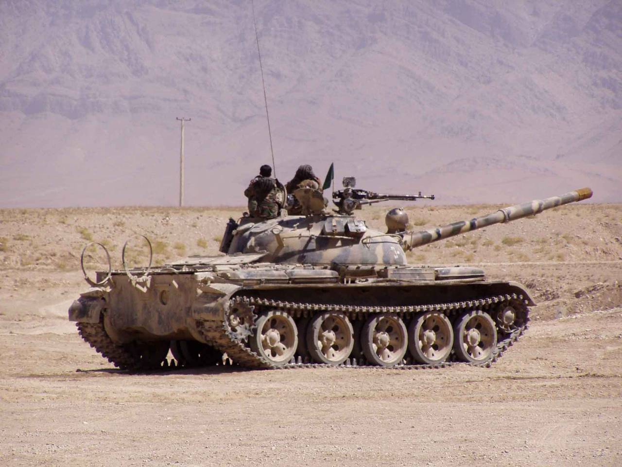
On the advantages and disadvantages of this engine remembers S. Suvorov, in his book "T-64".
On the T-64A tanks produced from 1975 of the year, the reservation of the tower was strengthened through the use of corundum filler.
These machines also increased the capacity of fuel tanks from 1093 liters to 1270 liters, as a result of which a spares box appeared on the back of the tower. On machines of previous releases, spare parts and equipment were placed in boxes on the right fender, where they installed additional fuel tanks connected to the fuel system. When installed by the driver-mechanic of the distribution valve to any group of tanks (rear or front), the fuel was produced primarily from external tanks.
In the caterpillar tensioning mechanism, a worm pair was used, which allowed its operation without maintenance during the entire service life of the tank.
The performance characteristics of these machines have been significantly improved. For example, the trial before the next number service was increased from 1500 and 3000 km to 2500 and 5000 km for T01 and THEN, respectively. For comparison, the T-62 TO1 TO2 was conducted through 1000 and 2000 kilometers, and on the T-72 tank — via 1600-1800 and 3300-3500 kilometers, respectively. The warranty period for the 5TDF engine was increased from 250 to 500 hours, the warranty period for the entire machine was 5000 kilometers.
But the school is just a prelude, the main operation began in the army, where I got after graduating from school in 1978 year. Just before the release, the order of the Commander-in-Chief of the Ground Forces to us that the graduates of our school were distributed only to those units with T-64 tanks. This was due to the fact that the troops had cases of mass failure of T-64 tanks, in particular, 5TDF engines. The reason is ignorance of the material part and the rules of operation of these tanks. The adoption of the T-64 tank was comparable to the transition in aviation from piston engines to jet ones - aviation veterans remember how it was.
As for the 5TDF engine, there were two main reasons for its failure in the army - overheating and dust wear. Both reasons occurred through ignorance or neglect of the rules of operation. The main disadvantage of this engine is not too designed for fools, sometimes it requires that they do what is written in the instruction manual. When I was already a tank company commander, one of my platoon commanders, a graduate of the Chelyabinsk Tank School who trained officers for T-72 tanks, somehow began to criticize the T-64 tank propulsion system. He did not like the engine and the frequency of its service. But when he was asked the question, “And how many times in six months did you open the roofs of MTO on your three training tanks and looked into the engine compartment?” It turned out that never. And the tanks went, provided combat training.
And so in order. Overheating of the engine occurred for several reasons. The first - the mechanic forgot to remove the mat from the radiator and then did not look at the devices, but this happened very rarely and, as a rule, in the winter. The second, and the main - refilling the coolant. According to the instructions, it is necessary to pour water (in the summer period of operation) with a three-component additive, and the water must be poured through a special sulfofilter, with which early release machines were completed, and on new machines such filter was given out one per company (10-13 tanks). The engines, mainly tanks of the operational training group, which operated for at least five days a week and are usually located in ranges in field parks, failed. At the same time, the mechanics-drivers “textbooks” (the so-called mechanics of training machines), as a rule, hard workers and conscientious guys, but who did not know the details of the engine, could sometimes afford to pour water into the cooling system just from the tap, The sulfofilter (which is one for the company) was usually stored in winter quarters, somewhere in the company room of a techtech company. The result is the formation of scale in the thin channels of the cooling system (in the area of the combustion chambers), the absence of liquid circulation in the most heated place of the engine, overheating and engine failure. The formation of scale aggravated the fact that the water in Germany is very hard.
Once in the next unit, the engine was withdrawn due to overheating due to the fault of the driver. Finding a small coolant leak from the radiator, he, on the advice of one of the "experts" to add mustard to the system, bought a pack of mustard in a store and poured it all into the system, resulting in clogged channels and engine failure.
There were also other surprises with the cooling system. Suddenly, it begins to expel the coolant from the cooling system through the vapor-air valve (PVC). Some, not understanding what's the matter, are trying to start it with a tug - the result of the destruction of the engine. Thus, my battalion deputy engineer gave me a “gift” for the New Year, and I had to change the engine of December 31. Before the New Year, I managed, because Replacing the engine on the T-64 is not a very complicated procedure and, most importantly, does not require centering when installing it. Most of the time when replacing the engine on the T-64 tank, as in all domestic tanks, is the procedure for draining and refilling oil and coolant. If instead of pipelines joints on our tanks there were connectors with valves, like on Leopards or Leclercs, then replacing the engine on T-64 or T-80 tanks in time would take no more than replacing the entire power unit with western ones tanks. So, for example, on that memorable day of 31 December 1980, after draining the oil and coolant, we with Ensign E. Sokolov “threw out” the engine from the MTO in just 15 minutes.
The second reason for the failure of 5TDF engines is dust wear. Air purification system. If the coolant level is not checked in time, but it is necessary to check before each exit of the machine, then there may come a time when there is no liquid in the upper part of the cooling jacket and local overheating occurs. In this case, the weakest point of the nozzle. In this case, the nozzle gaskets are burning or the nozzle itself fails, then through cracks in it or burnt gaskets gases from the cylinders break through into the cooling system, and under their pressure, the liquid is expelled through the PVC. All this is not fatal to the engine and is eliminated if there is a knowledgeable person in the unit. In conventional in-line and V-shaped engines in a similar situation, “leads” the cylinder head gasket, and there will be more work in this case.
If in such a situation the engine is stopped and no measures are taken, then after some time the cylinders will begin to fill with coolant, the engine is an inertial grille and a cyclone air cleaner. The air cleaner according to the instruction manual is washed as necessary. On T-62 type tanks, it was flushed in winter through 1000 km of run, and in summer through 500 km. On the T-64 - as needed. This is where the stumbling block - some have taken it as something that can not be washed at all. Necessity arose when oil fell into the cyclones. And if there is oil in at least one of the 144 cyclones, then the air cleaner should be rinsed, as through this cyclone the engine receives unclean air with dust, and then, like sandpaper, cylinder liners and piston rings are erased. The engine begins to lose power, oil consumption increases, and then stops running completely.
It is not difficult to check the oil penetration into the cyclones - just look at the cyclone inlets on the air cleaner. Usually they looked at the dust outlet from the air cleaner, and if oil was found on it, then the air cleaner was also looked at, and if necessary, washed. Where did the oil come from? Everything is simple: the filler neck of the oil tank of the engine lubrication system is located next to the air intake mesh. When refueling with oil, a watering can is usually used, but since again, on the training machines, watering cans, as a rule, were absent (someone lost, someone put on the track, forgot and drove through it, etc.), then the mechanics poured oil just from buckets, while the oil was spilled, first fell on the air intake grid, and then into the air cleaner. Even filling the oil through a watering can, but in windy weather, the oil splashed with wind on the air cleaner grid. Therefore, from my subordinates, I required to lay a mat from the spare parts of the tank onto the air intake grid when refueling the oil, thus avoiding trouble with the engine's dust wear. It should be noted that the conditions of dust in Germany in the summer were the most severe. So, for example, during divisional exercises in August 1982, when making a march through the forest glades in Germany, because of the hanging dust, it was not even visible where the barrel of the gun of its own tank ends. The distance between the cars in the column was kept literally by the scent. When there was literally a few meters left before the tank ahead, one could discern the smell of its exhaust gases and slow down in time. And so 150 kilometers. After the march, everything: tanks, people and their faces, overalls and boots were the same color - the color of road dust.
Diesel 6TD
Simultaneously with the design and technological development of the 5TDF diesel, the design team of HKBD began to develop the next model of the 2-stroke diesel engine already in the 6-cylinder design with increased power up to 735 kW (1000 hp). This engine, as well as 5TDF, was a diesel with horizontally placed cylinders, counter-moving pistons and direct-flow purging. Diesel received name 6TD.
Turbocharging was carried out from the compressor, mechanically (spring) connected to the gas turbine, which converts part of the heat energy of the exhaust gases into mechanical work to drive the compressor.
Since the power developed by the turbine was not enough to drive the compressor, it was connected to both engine crankshafts using a gearbox and transmission mechanism. The compression ratio was assumed to be 15.
To obtain the required valve timing, which would provide the necessary cleaning of the cylinder from the exhaust gases and filling with compressed air, it was provided (as on the 5TDF engines) angular displacement of the crankshafts in combination with an asymmetrical arrangement of the intake and exhaust windows of the cylinders along their length. The torque taken from the crankshafts is for the intake shaft - 30%, for the exhaust - 70% of the engine torque. The torque developed on the intake shaft was transmitted through a gear transmission to the exhaust shaft. The total torque could be removed from both ends of the exhaust shaft through the power take-off clutch.
In October, 1979. The 6TD engine, after a serious revision of the cylinder-piston group, fuel equipment, air supply systems and other elements, successfully passed interdepartmental tests. From 1986. The first serially manufactured 55 engines were manufactured. In subsequent years, serial production increased and peaked at 1989.
The percentage of total unification 6TD with a diesel 5TDF was more than 76%, and the reliability of operation was not lower than that of 5TDF, which has been mass-produced for many years.
The work of HKBD under the direction of the chief designer N.K. Ryazantsev on the further improvement of the 2-stroke tank diesel continued. Modules, mechanisms, and systems were developed that were used to detect individual defects in operation. Improved boost system. Conducted numerous bench tests of engines with the introduction of design changes.
Developed a new modification of the diesel - 6TD-2. Its power was no longer 735kW (1000l.s), as in 6TD, but 882 kW (1200l.s). Its detailed unification with the 6TD diesel engine was provided by more than 90%, and with the 5TDF diesel engine - more than 69%.
Unlike the 6TD engine, the 6TD-2 engine was equipped with a 2-speed axial centrifugal compressor of the pressurization system and changes in the design of the turbine, bellows, oil centrifugal filter, branch pipe and other components. The compression ratio was also slightly reduced from 15 to 14,5 and the average effective pressure was increased from 0,98 MPa to 1,27MPa. The specific fuel consumption of the 6TD-2 engine was 220 g / (kW * h) (162 g / (hp * h)) instead of 215 g / (kW * h) (158g / (hp * h)) - for 6TD. In terms of installation in the tank, the diesel 6TD-2 was completely interchangeable with the engine 6DT.
In 1985 Diesel 6TD-2 passed interdepartmental tests and design documentation was submitted for the preparation and organization of mass production.
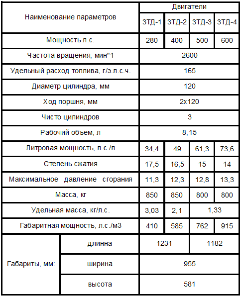
In KKBD with the participation of NIID and other organizations continued research and development work on the 2-stroke diesel 6TD in order to force it to the power to the value 1103 kW (1500l.s.), 1176 kW (1600l.s.), 1323 kW (1800l.s.) with the conduct of checks on the samples, as well as the creation on its basis of a family of engines for VGM and economic machines. For VGM light and intermediate categories by weight, diesel engines 3ТD with power 184… 235 kW (250-320л.с.), 4ТD with power 294… 331 kW (400… 450л.с.) Were developed. A version of the 5DN diesel engine 331… 367 kW (450-500л.с.) For wheeled vehicles was also developed. For transporters and engineering vehicles, the project was developed for a diesel 6DN power 441 ... 515 kW (600-700л.с.).
Diesel 3TD
The three-cylinder ZTD engines are members of a single unified series with the 5TDF, 6TD-1 and 6TD-2E series engines. At the beginning of the 60-x in Kharkov, a family of engines was created based on the 5TDF for light-weight vehicles (BTR, BMP and others) and heavy weights (tanks, 5TDF, 6ТD).
These engines have a single design scheme:
- push pull cycle;
- horizontal arrangement of cylinders;
- high compactness;
- low heat transfer;
- possibility of use at ambient temperatures
environments from minus 50 to plus 55 ° C;
- low power reduction at high temperatures
the environment;
- multi-fuel.
In addition to objective reasons, mistakes were made in creating a family of two-stroke boxer diesel 3TD engines in the middle of 60's. The idea of the 3-cylinder engine was tested on the basis of the 5-cylinder, in which two cylinders were plugged. At the same time, the gas-air duct and the supercharging units were not coordinated. Naturally, the power of mechanical losses was increased.
The main obstacle for the creation of a unified engine family in 60-70-s was the lack of a clear engine development program in the country, the manual was “darting” between various concepts of diesel engines and gas turbine engines. In the 70-s with the advent of the leadership of the country L. I. Brezhnev, the situation became even more aggravated, the parallel production of tanks with different engines - T-72 and T-80, which by their characteristics were “tank-analogues” of the already produced T- 64. Speech about the unification of the tank engines, infantry fighting vehicles and armored personnel carriers have not been.
Unfortunately, the same situation was in other branches of the military industrial complex - at the same time various design bureaus in rocket production and aircraft construction were being developed, while the best were not selected among them, but similar products were made in parallel by different Design Bureau (design bureau).
Such a policy was the beginning of the end of the domestic economy, and the cause of the lag in tank building, efforts instead of uniting into a “single fist” were scattered on parallel developments of competing design bureaus.
Light machines (LBMs), produced in 60 ... 80-ies of the last century, have engines of outdated design, which provide power density within 16-20 hp / t. Modern machines must have power density 25-28 hp / t, which will increase their maneuverability.
In 90, 2000, modernization of the LME - BTR-70, BTR-50, BMP-2 became topical.
During this period, tests of these machines showed high performance of the new engine, but, at the same time, a large number of UTD-20СXNNUMX engines were stored and manufactured in Ukraine after the collapse of the USSR.
General designer of tank construction of Ukraine MD. Borisyuk (KMDB) for the modernization of these machines decided to use the available serial engines - SMD-21 UTD-20 and the German "Deutz".
Each vehicle was installed its own engines, which do not have unification with each other, and with engines already in the army. The reason is that for repair plants of the Ministry of Defense it is advantageous to use the engines that are available in the customer’s warehouses, which makes it possible to reduce the cost of work.
But such a position deprived the work of the state enterprise “Plant named after V.A. Malysheva "and, above all, an aggregate plant.
This position was ambiguous - on the one hand, saving, on the other - the loss of perspective.
It is worth noting that in the KMDB with respect to 3TD a number of claims were made (for noise and smoke), which were accepted and eliminated.
In order to reduce smoke at start-up and during transient conditions, a closed fuel equipment was installed on the engine of the ZTD and the oil consumption was significantly reduced. Noise reduction is ensured by reducing the maximum combustion pressure and reducing the gap in the piston-cylinder pair on 280 and 400 engines, hp, as well as reducing the range of torsional vibrations
The reduction in oil consumption on ZTD engines was achieved due to the following factors:
- reducing the number of cylinders;
- use of a piston with a cast-iron casing instead of an aluminum alloy;
- increase the specific pressure of the oil scraper ring on
cylinder wall.
As a result of the measures taken, the relative oil consumption on ZTD engines approaches the consumption of engines for economic purposes.
Information