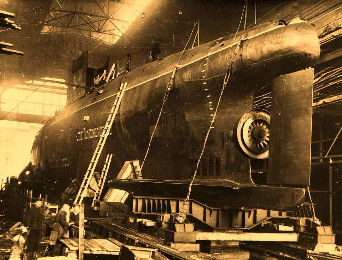
Submarine with steam-gas turbine C-99. 617 project
The search for new types of power plants capable of providing high speed when submarines move underwater is conducted in Russia, and then in the USSR constantly. Especially widely they turned around in the thirties of our century. Then we took the path of using liquid oxygen to ensure the work of diesels in a submerged position. The pioneer in this field can be considered our talented engineer S.А. Bazilevsky. Following him, several other options for using liquid oxygen were proposed and implemented, some of which were introduced into the practice of shipbuilding. In addition, at the end of 1944, experiments were conducted on the use of hydrogen peroxide as the oxygen carrier. It was intended for the oxidation of fuel in the working chamber of the steam generator. These experiments did not arouse much enthusiasm, obviously, for two reasons - because of the low concentration of hydrogen peroxide used and the imperfection of the proposed scheme for its use.
In the 1945 year, after the end of the war, special groups of engineers were sent from the USSR to Germany to learn German experience in various industries. Among them were shipbuilders, submariners. Engineers Vladimir Konstantinovich Stankevich and Isaak Samoilovich Toltraf got acquainted with the original combined-cycle turbine previously ordered by the naval department in the Dresden-based firm Bruner-Kanis-Reder. She had the power of 7500 HP at 10000 rpm, and the time to get out of the cold state to full speed was 5 minutes. Its working fluid was steam gas, for which high-concentration hydrogen peroxide was used.
The development of the turbine led the bureau, which was called "Glukauf" ("happily upward" - it.). Former employees of this bureau were gathered around 15, and they were offered to resume work, starting with restoring the lost documentation on the project of the submarine of the XXVI series with the Walter afterburner turbine combined-cycle plant (PGTU). To this end, a “joint” design office was organized in Germany.
He was headed by engineer captain 1 rank A.A. Antipin, who headed the Leningrad Design Bureau (TsKB-18), which designed all the Soviet submarines of pre-war and military construction and grew out of a bureau created by an outstanding engineer-shipbuilder, designer of the first domestic combat submarines IG Bubnov. BD was appointed chief engineer of the new design bureau. Zlatopolsky, who headed the department of special power plants of the Central Research Institute of Shipbuilding, where in those years much of the work was concentrated on the problems of creating power plants designed to ensure high submarine speeds in a submerged position.
The new design bureau, named after the head of its “Antipin Bureau,” consisted of workers from TsKB-18, the Central Research Institute of Shipbuilding and German specialists, whose chief engineer was Dr. Stateshny. The number of employees of the bureau included S.N. Kovalev, who led the corps department, and V.K. Stankevich, who headed the mechanical department.
First of all, the bureau was engaged in the restoration of the German project of the submarine XXVI series, and then Antipin, Stankevich, the senior group of German specialists at State, visited all the companies that manufactured equipment for the steam and gas turbine installation and concluded contracts with them. It was possible to order a complete set of equipment, except for the screw compressor of the Lysholm company, since it was not in Germany, but in Sweden.
Work went fast. All the documentation prepared at the Antipin Bureau, as well as the equipment obtained for the steam and gas turbine installation, were sent to Leningrad. There, in the 1946 year, the Central Design Bureau-18 reinstated the design of the submarine of the XXVI series in the form of a pre-draft version, as presented by the Glukauf bureau. This work was done under the guidance of S.A. Yegorova, monitoring the course and consultations were conducted by BM Malinin - the first chief designer of the majority of Soviet submarines, who worked at that time in the Central Research Institute of Shipbuilding.
The project received an 616 number. However, a number of technical solutions used on submarines of the German XXVI series did not satisfy our naval sailors and designers (a small reserve of buoyancy, onboard torpedo tubes were sent to the stern; a large volume of compartments of a strong hull, etc.). Therefore, immediately after the critical review of this version, TsKB-18 began the development of a new submarine project with a steam and gas turbine unit, which was assigned the number 617.
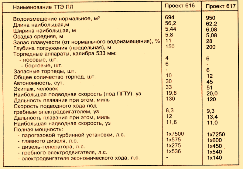
On the submarines of this project, all the equipment, with the exception of the gas and gas turbine installation, was domestic. The predesign 617 appeared at the end of 1947. Works on it were conducted under the guidance of the most experienced mechanical engineer PS. Savinov, a participant in the creation of all Soviet submarines, and a young engineer S.N. Kovalev, who later became the general designer of nuclear submarines. The project was carried out under the supervision of a previously mentioned BM. Malinin, for whom he was the last in his life, cut short in 1949 year.
After analyzing the various options for the pre-sketch project, the tactical and technical requirements for its further development were compiled and approved. This was given particular importance, since the expected high submarine speed of these submarines made it possible to evaluate in a different way the tactics of their use and their place in the Russian Navy.
For the further development of the submarine with new energy in May 1948, the second in the USSR underwater design bureau, SKB-143, was created. It consists of a group of specialists from TsKB-18, employees of the Antipin Bureau in Germany (including German specialists 10), as well as the staff of the department of special power plants of the Central Research Institute of Shipbuilding. A.A. was appointed the head of the bureau and chief designer of submarines of the 617 project. Antipin, his assistant - S.N. Kovalev.
It is worth noting that in the spring of 1953, the team that worked on creating the 617 project was returned to the Central Design Bureau No. 18 along with its entire “order book”, and SKB-143 was from this point redeployed to develop the project of our first nuclear submarine.
After creating the conceptual and technical parts of the 617 project, which did not significantly change the originally planned appearance of the submarine, the bureau staff handed over to the Sudomekh plant a set of working drawings for the construction of the ship. It should be noted that the uniqueness of the project led to the decision to build first only one experienced submarine, the question of building such a series was postponed until the end of its tests. In parallel, the designers have developed some more promising projects of submarines using low-water hydrogen peroxide (MPV), but this is a topic for a separate story.
When creating an experimental submarine project 617, the design bureau assumed a number of additional functions that were usually not the responsibility of the designer. For example, by power of attorney of the construction plant, the bureau employees received equipment from the supplying plants, carried out contract supervision and test maintenance of the steam and gas turbine unit; completely completed the installation of low-water hydrogen peroxide system, including storage bags for MPV. The purchase, transportation, storage and loading of low-water hydrogen peroxide on a submarine was also carried out by the design office.
Delivery of the basic materials for the test of a combined-cycle turbine plant (PGTU): MPV, fuel, catalyst for the decomposition of hydrogen peroxide and other things - to the builder of basic materials was carried out through the design office. In one of the workshops of the Sudomekh plant, transferred to the design bureau, there was a test stand, the main components of which were the storage for hydrogen peroxide and the hull of the turbine compartment of the future submarine. In this case, a bench-mounted steam and gas turbine unit was installed, which most closely corresponded to boat conditions and made of elements and parts obtained from Germany. The missing parts were made on site, in the mechanical workshop of the design office. To ensure the possibility of testing PSTU over the entire power range, up to the full, the hydraulic motor was installed outside the compartment, which with the help of interchangeable wheels reproduced the characteristics of the submarine propeller of the 617 project. It also housed "outboard" condensate cooler.
The test program for a bench-top gas turbine installation was divided into five main stages: Stage I - testing the hydrogen peroxide decomposition chamber in a special armored box; II - power unit tests: a three-component pump, a four-component regulator and a three-component switch; III - testing of the gas-vapor mixture generation unit; IV - tests of a condensate system consisting of a turbine condenser, a condensate outboard cooler and a condensate pump, and V - comprehensive tests of the entire installation, including the determination of start-up time and transitions from mode to mode, output to 100-percent power and 6-hour continuous operating mode at full power.
Testing at PSTU was headed by its chief designer V.K. Stankevich. The heads of the first four stages were engineers Evgeny Nikolaevich Gurfein, Ilya Moiseevich Ozerov, Petr Petrovich Petrov and Olga Vladimirovna Kovalevskaya. German colleagues participated in the work as consultants on a number of technical issues that arose and were located in a separate room. As they gained experience, their role became less and less, and in 1951, these specialists returned to their homeland.
At the very beginning of 1951, the PSTU bench tests were completed. In May of the same year, the PSTU bench was dismantled, all its mechanisms, devices and devices underwent a thorough audit and inspection. After eliminating the comments and replacing the elements that had developed their life, the installation itself and its control panel were mothballed and transferred to the Leningrad Sudomekh plant for installation on an experimental submarine, the construction of which was in full swing.
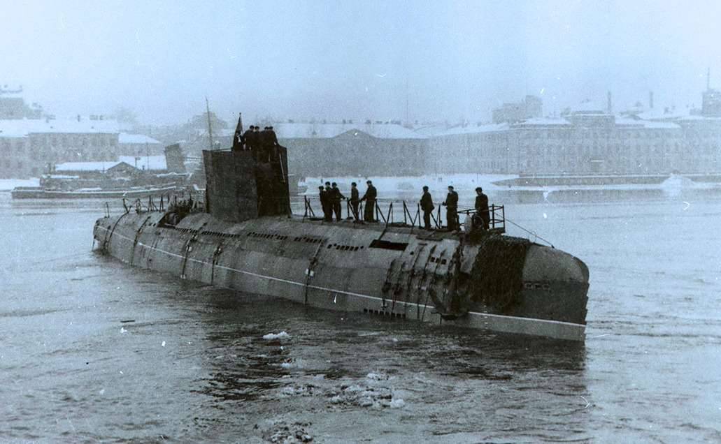
The laying of the experimental submarine project 617 with the tactical number С-99 took place on February 5 of the year 1951. Exactly one year later, this submarine was launched, and 16 June 1952 began its mooring trials.
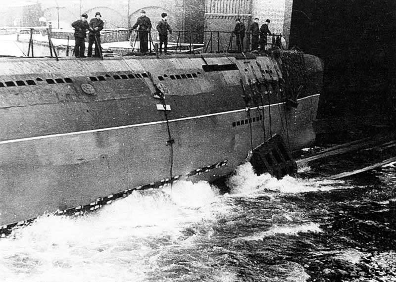
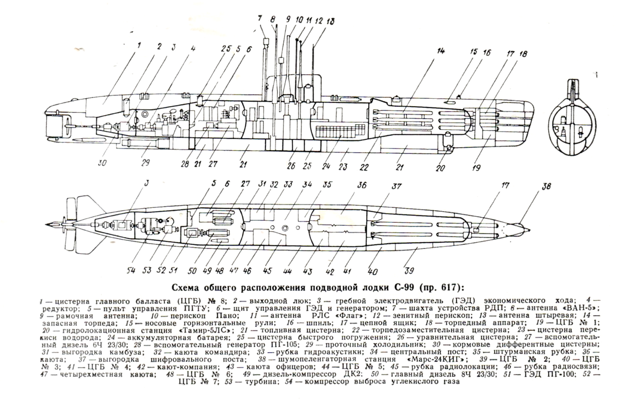
Relatively short, with a slightly elongated hull, a small, well-rounded fencing of the access hatch shaft (there was no warhead) and the correct plumage by the designers, the C-99 showed the required speed and maneuverability characteristics. The boat had 6 compartments separated by watertight bulkheads: torpedo, battery (residential), central post, diesel, turbine, aft. In the double-hull space there were eight bingongstone tanks of the main ballast, fuel tanks and permeable fences with 32 plastic storage bags of low-water hydrogen peroxide.
A good reserve of buoyancy and the separation of a solid hull of the boat with waterproof bulkheads ensured the surface unsinkability of the submarine in case of flooding any of the compartments of the robust hull, together with the adjacent ballast tank adjacent to it.
The power plant has become the main feature of the C-99 submarine. As mentioned earlier, as the afterburner part of this installation, the PSTU was installed, the maximum power of which reached 7250 hp. When the submarine was moving at a depth of the order of 40 meters, the power transmitted to the propeller shaft was equal to 6050 hp, the rest was consumed by a screw compressor, which pumped carbon dioxide overboard the boat. The installation could be started at depths from periscope to 80 meters, the start time was 2 min 10 s; The forced cold start with the maximum power output was carried out in nine and a half minutes.
When operating PSTU at full power, the speed of the C-99 submarine exceeded 20 knots. Such a high submarine speed and 6-hour cruising range on it (120 miles) greatly expanded the combat capabilities of such submarines. Although today the schematic diagram of the operation of the combined-cycle turbine plant using low-water hydrogen peroxide (MPV) is well known, let us recall in brief for those who first meet with submarines of this type.
Seawater pressure MPV from flexible PVC bags was squeezed to the pumping and three-component pump (MPV, fuel, condensate) and fed to a special decomposition chamber, where it was converted into oxygen gas (37% by volume) and water vapor (63%) using a catalyst. Steam oxygen was sent to the combustion chamber, where kerosene was injected with a low content of impurities and a high flash point. The combustion products, as part of 15% СО2 and 85% of water vapor, passed through a heat accumulator, which served to equalize the thermal inertia of the vapor gas and entered the turbine. The temperature of the steam gas was constant (550 ° C), the pressure changed depending on the load and was about 21 kgf / sq. Cm during the rotation of the 9500 turbine rpm. After the turbine, the exhaust steam gas went into a condenser, where water was separated from carbon dioxide, which was compressed with a screw compressor to outboard pressure and was ejected using a special spraying device with 10000 small holes, which ensured a good dissolution of CO2. A self-flowing cooler was used to cool the condensate, located in the double-breasted space under the durable hull of the boat; part of the cooled condensate was used to adjust the temperature of the vapor gas.
The two-stage gearbox reduced speed to 480 rpm and transferred them to the propeller shaft. The movement of the submarine at lower speeds and in the surface position was carried out using a diesel-electric installation, consisting of the main eight-cylinder four-stroke and auxiliary six-cylinder diesel generators of the same design. The main diesel engine through couplings worked on the screw or only on the generator; the auxiliary provided either the charging of the battery or the work of the propulsion motors. It was possible to work both diesel engines on the propeller, both in the surface position and in the periscope with the help of a collapsing shaft of the RDP (the work of the diesel engines in the periscope position).
The electric movement was carried out by the main propeller motor or an economic stroke motor connected by a non-parting coupling to the shaft line passing inside it. Despite the long-term testing of the steam and gas turbine installation on the stand, a number of problems occurred during the mooring and sea trials of the C-99 submarine: leakage of hydrogen peroxide storage bags; the appearance of hydrogen peroxide leaks, in which from its rapid decomposition in contact with contaminated and, especially, oiled objects, fires and weak explosions, called “claps”, occurred; insufficient stability of the catalyst, etc.
During the factory tests it was also found that the zone of torsional oscillations of the main diesel engine has a greater range of revolutions than was calculated. Eliminating these shortcomings delayed the test period, and only 20 in March 1956, after successfully completing the state tests, the C-99 submarine was put into trial operation, which completed almost twelve years of its creation. The work of the design bureau, the construction plant of the submarine, a number of research and design organizations ended successfully.
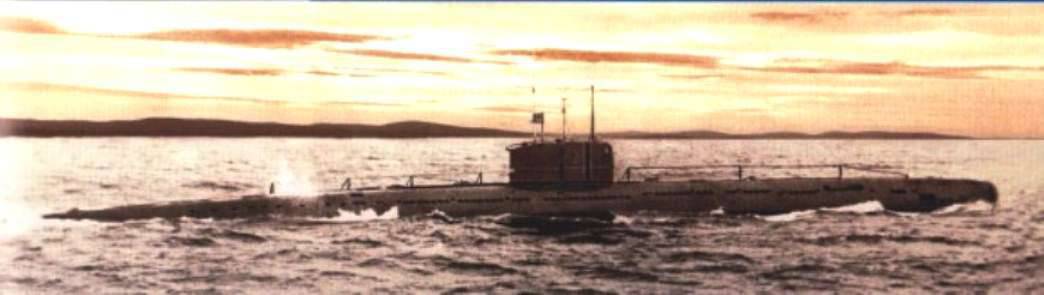
From 1956 to 1959, the experimental submarine S-99, being in a separate brigade of training boats of the Baltic fleet, completed 98 exits to the sea, having covered more than 6000 miles in the surface position and about 800 miles in the underwater position.
19 May 1959 on C-99 there was a serious accident. At the next launch of PSPU at a depth equal to 80 m, an explosion occurred in the turbine compartment - the installation did not start. The boat commander gave the command to immediately blow the main ballast with an emergency blowing system. The boat floated with aft on the stern. A report was received from the diesel compartment: “Fire and explosion in the 5-m (turbine) compartment, irrigation in the 5-th compartment was given.”
On the ship declared an alarm. Using the viewing glasses of adjacent compartments, it was established that the 5 is filled with water. Since the submarine kept afloat, the commander decided to get to the base under its own power. They launched high-pressure compressors and continuously inflated damaged tanks of the main ballast. A few hours later, C-99 returned to base. After draining the turbine compartment, it was found that the onboard valve of the hydrogen peroxide loading pipeline collapsed; a through hole with a diameter of 80 mm, through which the turbine compartment was flooded, was punctured in the upper part of the robust case. The explosion caused the decomposition of hydrogen peroxide due to dirt entering the valve.
After the accident, the experienced C-99 submarine was not restored, because it needed to replace a significant part of the PGGU mechanisms, which required considerable expenses. By this time, the first nuclear submarine of the 627 project, the K-3, entered the Soviet Navy. The complex and interesting search for new power plants has ended. The C-99 submarine was disarmed and scrapped, but the experience gained in using combined-cycle turbine plants on the submarines played a very significant role in the creation of nuclear steam-turbine installations for submarines.
Sources:
Badanin V. “Single U-Boat Submarines”, St. Petersburg: Gangut, 1998. C. 48-86.
Boechin I. Soviet and British Walters // Technique-Youth. 1996. No.5.C.32-36
Shirokorad A. Submarine project 617. // Soviet submarines of post-war construction. M .: Arsenal Press. 1997. C.160-166.
Spassky I., Semenov V. Project 617 // Sea collection. 1995. No.7. C.65-69.
Antonov A. Iz stories creation of submarines with steam-gas turbines. // Shipbuilding. 1994. No.5-6. C.64-67.
Information