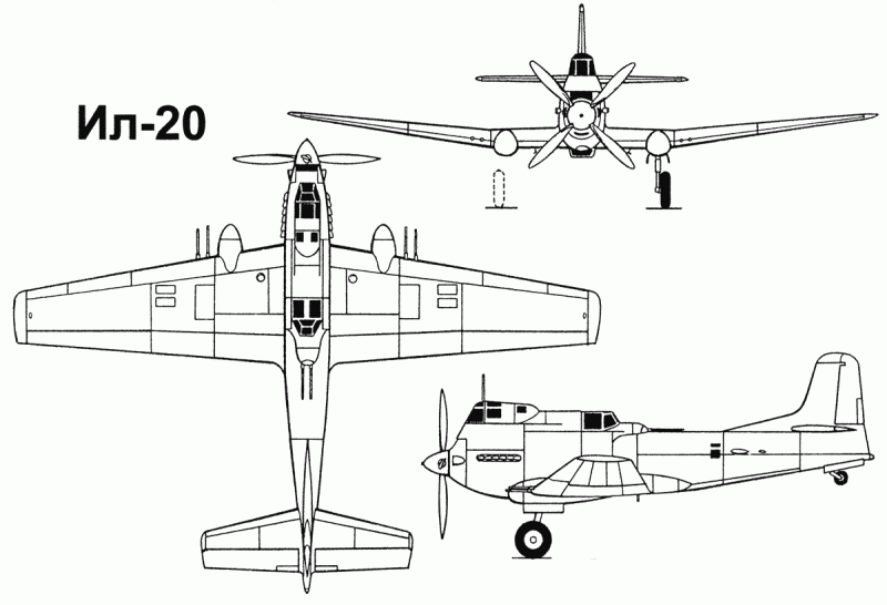
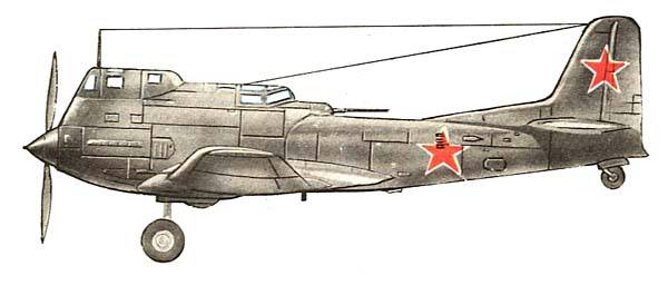
Experienced attack aircraft IL-20
At the end of the 30-x - the beginning of the 40-s, the main and practically the only tactical tactic for attack aircraft was an attack from horizontal flight at extremely low altitudes (from a strafing flight). And at that time, and later - in 1950-x, when designing single-engine attack aircraft using the traditional layout of their layout, the designers were obliged to provide a fairly good overview of the forward - down. For airplanes with air-cooled engines, this problem turned out to be particularly difficult. A review in this direction is necessary so that the pilot can quickly and correctly assess the situation on the battlefield, identify targets, determine the opposition of enemy ground weapons, select a target and maneuver for its attack, make aim, and have time to use the offensive weapons as efficiently as possible. Since attack aircraft were often used as light bombers, a good downward view, directly under the aircraft, was also important to ensure accurate bombing. The viewing angle of the TS-2 M-34 (the most visible among our first armored attack aircraft) did not even reach one degree. When flying at an altitude of 15 m, the pilot could see targets that were at a distance of at least 1000 meters ahead. This completely eliminated the shooting of machine guns.
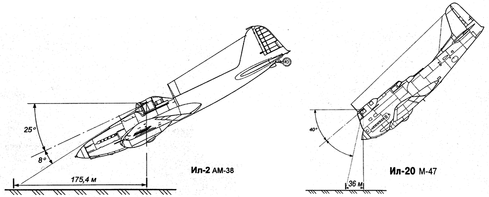
Creating the Su-6, to get a more or less satisfactory view ahead - down, P.O. Sukhoi spent a long time looking for a place under the engine and carefully chose the engine hoods. On this machine, the optimal solution was found. On the FW-190F aircraft, even in the version with a slightly raised pilot seat, the forward-down view was almost absent. S.V. Ilyushin to improve visibility on BSH-2 (IL-2) was forced to raise the seat of the pilot, lower the engine relative to the axis of the aircraft, pay much attention to the contours of the engine hood. As a result, he provided a forward-downward viewing angle of about 8 degrees, which was considered acceptable (although a value equal to 30-35 degrees would be desirable).
All serial attack aircraft did not have a review down under the plane. The exception was IL-2, equipped with a special periscope, which, however, did not receive further distribution. The way out was found using the time delay for dropping bombs, either with the help of special sights and temporary mechanisms, or by marking marks on the structural elements of the aircraft. Sometimes, in order to increase the effectiveness of the Il-2 aircraft from a strafing flight, it was necessary to make them “sighted” with the help of target airplanes for attack aircraft (STSUS). In this capacity, flight and search targets at medium altitudes of the SS, Pe-2, and subsequently - specially selected IL-2 crews were used. After the discovery of the object of attack, the navigator or pilot STSUS dropped bombs and thereby designated it.
At the end of 1940, designer S.А. Kocherigin presented to NCAA a draft design of a multipurpose single-seat OPB battlefield aircraft with an AM-37 engine (including an attack aircraft), in which he consciously went for some deterioration in aerodynamics. To ensure a good (up to 15 degrees) forward-down view, it provided for a high placement of the pilot with a corresponding increase in the size of the cockpit canopy. In addition, a special glazing was developed for the cockpit floor and the manhole covers under it, which gave an additional view of the area directly under the aircraft.
The new machine was the development of the previously designed and under construction single-engine bomber OPB M-90 and according to the scheme it was a mid-wing with a “reverse seagull” wing, with a normal-type tail unit. Chassis with tail wheel, retractable, mixed design. The middle part of the wing was a center section connected to the fuselage. Consoles had a production connector at the turn of the "seagull". When transporting the weaning of the wing was carried out at the fuselage. The wing is metallic, single-spar, with a working casing (steel spar). Profiles open. Ribs are duralumin, stamped. A relatively thick, trapezoidal wing in plan with rounded ends, with well-developed mechanization — automatic slats, hovering ailerons and flaps. NASA-230 wing profile. The thickness along the axis of the aircraft is 19%, by fracture - 16%, at the ends - 7%.
The front part of the fuselage is duralumin, the tail part is made of wood. The fuselage section is elliptical. The lantern is made of plexiglass, its emergency discharge was provided. The pilot's seat at the back and bottom was covered with 13 mm thick armor, which protects against 12,7 mm bullets and shells aviation guns. It was also supposed to put an armored visor. The keel was made in one piece with the fuselage. The rudder and horizontal tail are duralumin, sheathed with canvas. The rudders had weight and aerodynamic compensation. The chassis was hydraulically retracted, emergency release was performed by an air system. The main brake wheels were retracted into the wing to the fuselage, the tail wheel - into the aft fuselage. Under the cockpit floor, a mine was provided for bombs with a caliber of up to 500 kg.
Steering and aileron rigid, with ball bearings. Trimmers piloted. Three-bladed screw. Two water radiators were located under the center section, one - in the sock of the motor. The oil radiator was also wearing an engine sock. There were four fuel tanks with a total capacity of 510 liters. Instead of a bomb, an extra 500-liter gas tank could be placed in the bomb bay. In the engine nacelle above the engine blocks there was an oil tank of 70 liters. On the sides of the engine were two exhaust manifolds. The outdoor antenna was a three-beam.
The aircraft's armament consisted of two synchronous BSs and two synchronous ShKAS with 400 and 1500 rounds of ammunition, respectively. Machine guns were placed on a special farm on a motor frame: on the right - ShKAS, on the left - BS. In the overload under the wing could fit two guns caliber 20-23 mm. Provided for the use of three bomb racks that provided dive-bombing. In the fuselage bomb bay on the parallelogram one of the following types of bombs could be suspended: FAB-500, BRAB-500, FAB-250, BRAB-200, BETAB-150. For aiming provided sight PB-3. Under the wing, the aircraft could carry bombs with a caliber of 100 and 250 kg for dive bombing, which was carried out with the help of a PBP-1 sight (it was also used when firing machine guns). If necessary, it was possible to place three PO-82 guns with PC-82 rocket projectiles on the fuselage bomber holder.
The draft design was considered by the NCAP commission chaired by Academician B.N. Yuriev, with the participation of BCPyshnova and V.Polikovsky. The preliminary examination was conducted by the secretary of the commission Mashkevich. The result of their work was the conclusion that the flight characteristics are real, with the exception of the flight range - the designer did not have absolutely accurate data on specific engine consumption. The modification under AM-37 was recognized as expedient in the presence of positive results on testing the first OPB version with M-90. The protocol of the commission from January 23 1941 was approved by the Deputy People's Commissar of the aviation industry A.S. Yakovlev. At the beginning of 1941, S.O. Kocherigin sent the project OPB AM-37 to the Air Force Scientific Research Institute. The conclusion on it was approved 12 February 1941 g. Very high flight data specialists of the Research Institute of the Air Force considered quite realistic, noting that the aircraft compares favorably in the review, and will have the necessary stability. The draft design was approved and approved as the 2-th copy of the OPB plane under construction on the Resolution of the NCO of 7 in August 1940. It was proposed to force the construction of a machine with M-90 or M-89 engines and to provide Kocherigin with an independent production base for this.
Experts NII Air Force have contributed to the improvement of the aircraft. They proposed to increase the size of the tail wheel to 400x150 mm; make the lamp moving back, and the stabilizer - adjustable; somewhat reduce the area of vertical and horizontal tail; machine guns to place symmetrically, increase the ammunition of the BS to 500 cartridges; add wing guns; for a dive option, develop air brakes and provide a dive-out machine. We also recommended to consider the installation of AM-38 (in the 2 column of the 1 table, flight data of OPB with the AM-38 motor, obtained by us from the results of approximate calculations) are given. The plane, having booked a pilot only from behind and from below, would be close in speed to the IL-10 aircraft. And in terms of maneuverability, visibility, the maximum caliber of bombs, ensuring dive bombing would surpass it. We made a calculation of the flight data of the OPB and with the AM-42 motor, but on condition that 900 kg of armor will be added (see the 3 column of the 1 table). The flight speed turned out to be close to IL-10 while maintaining the advantages noted above.
The load on the wing would be too large, but given its powerful mechanization and the positive influence of the “return gull”, one would expect good maneuverability and takeoff and landing characteristics. The results of calculations confirm that the project deserved attention and had development prospects. Due to the lack of a finished engine, the built OPB M-90 was not tested for a long time. Then it was redesigned for M-89, installed the engine and began flight tests of the first instance of the aircraft. But M-89 was also not brought. Motor AM-37 has already been removed from mass production. In the documents there is information that they built both copies of the aircraft OPB, and that there was a plan to put on them the engine M-71, which also was not realized. Kocherigin did not dare to use the M-82, realizing that the flight data of the machine would be much lower. And lost. The production base of plant No. 156 was overloaded and as soon as the designer had a hitch, in the second half of 1942 he was forced out to a very honorable and responsible post of the chief editor of BNT TsAGI. It seemed that the most radical solution to the problem of providing a forward-down view was only using unconventional aircraft layout schemes.
The first such solution was a two-beam scheme with a fuselage-gondola, in the rear of which was placed the motor with a pushing screw. The project of an armored attack aircraft BS-MW AM-38 was developed by A.A. Arkhangelsky, G.M. Mozharovsky and I.V. Venevidov at the end of 1940. The idea of creating the aircraft belongs to Mozharovsky and Venevidov - designers of the plant №32, the authors of a number of developments, related to armaments: rifle turrets, sights, bomber armaments, combined rifle-gun installations for attack aircraft with weapons, shooting at an angle down from the axis of the KABV aircraft (combined artillery-bomber armament). To do this, they experimented with their KABV installations on SB 2М-103А, Yak-2 2М-103 airplanes and concluded that a special attack aircraft was needed, the basis of which offensive armament would be their combined cannon-gun installation. Offered and scheme of the machine. But, not having sufficient experience in this matter, the preliminary design did not work thoroughly. In particular, at that time it was believed that they chose too much load on the wing for attack aircraft (we note that later on all constructed armored attack aircraft it turned out to be about the same).
Designer A.A. Archangel and laid on him the leadership of the work. Here, the review problem was solved quite successfully (a forward-downward angle of about 15 degrees was provided), but there were difficulties of a different kind related to the pilot leaving the plane safely in flight and providing fire protection for the rear hemisphere. Operation of the aircraft with a propeller placed in the tail also required clear and clear recommendations from the designers. The BS-MV AM-38 draft design was presented to 29 December 1940, additional materials - January 25 1941. The draft design statement was approved by 12 March 1941, the head of the Air Force Scientific Research Institute A.I. Owl. The aircraft consisted of a single-engine single-engine monoplane with a two-beam scheme with a pilot's cabin, an AM-38 engine and armament (located in the gondola fuselage), a pushing propeller, a return-type wing, a retractable landing gear with a nose wheel.
The fuselage is armored, with a power transverse and longitudinal set. Armor cemented plates were the strength of the design elements. Aerodynamic forms in the nose and tail of the fuselage were formed by duralumin lining attached to armor plates - in the middle part of the fuselage, these plates were directly its surface, mating with the nose and rear parts of the fuselage. On the canopy of the lantern, on the sides of the pilot's head, as well as at his feet, transparent armor was placed. As well as on OPB AM-37 S.А. Kocheriigina, it was envisaged to provide a downward view directly under the aircraft, which made it possible to more effectively use KABV. The total weight of the armor was 845 kg, it defended the pilot himself, the engine, the gasoline and oil tanks, the radiators and all the equipment in the pilot's cabin.
Wing two-spar, all-metal. Spars, ribs and trim duralumin. The center section was one with the fuselage. Detachable console trapezoid in plan, with rounding. On the whole span of the center section and on the consoles of the Shrenka shields. The ailerons of the type "Fraze" during take-off and landing worked synchronously with the shields. Opposite the ailerons were automatic slats. NASA-23012 wing profile. The tail beams had a longitudinal and transverse set. Stringers, ribs and working trim - duralumin. The beams were rigidly attached to the reinforced ribs of the center section. The volume of the beams was used to be placed when the main wheels of the chassis were cleaned back, and the ends of the beams were used as reserve tail wheels (to protect the tail section when landing with a large angle of attack).
The tail plumage was metallic. Keels are made as one unit with tail beams. On the handlebars trimmers. The steering wheels are statically and dynamically balanced, the control is rigid, duplicated. The nose wheel was retracted back into the fuselage, under the cockpit. The main wheels on two racks. Cleaning and release of the chassis using a hydraulic drive. The armor plates of the rear fuselage served as an engine frame. Screw series ZSMV-2, diameter 3,2 meter. Behind the cockpit, a KABV was installed with Taubin’s 30-mm caliber guns with 23 projectile and 162 XKUM machine guns with 4 ammunition that could be deflected to 3000 degrees. Control by electric motor. The sight was synchronously connected with small arms and guns. The consoles provided for the suspension of six PC-82 rockets. Bomb holders were placed inside and outside the center section. Inside, there was a suspension of two bombs FAB-100, or four FAB-50, or six AO-25, or six AO-20, or one hundred forty-four AO-2,5, or boxes and tapes for ampoules and small-caliber bombs; outside - two FAB-250, two FAB-100, two FAB-50, four AO-25, four AO-20. The normal bomb load was 250 kg, while overload was 500 kg. Between the cartridge boxes and the motor AM-38 in the central part of the fuselage was located the fuel tank on the 930 l (700 kg), underneath the oil tank with a capacity of 70 liters. The water radiator was under the wing. Provided a fan for blowing the engine under the hood.
The final conclusions of the commission considered the draft said that the sustainability reserves are insufficient, but the aircraft layout is of some interest. The main advantage was considered an excellent review of the pilot, reaching 48% of the entire sphere. Strangely enough, the experts of the scientific research institute of the Air Force initially called in the KABV. The following wishes were put forward as the main ones: the attack aircraft must take at least 400 kg of bombs, mostly of small caliber; you must put a gun caliber 37 mm; add machine guns caliber 12,7 mm; to reduce the specific load on the wing, simplifying take-off and landing - the aircraft is massive and the quality of training of wartime pilots will be low; connect to the design of a powerful aircraft crew.
In general, the draft design approved. The plane was supposed to be unusually strong weapons, and only a misunderstanding of the advantages of KABV caused the desire to correct it. The construction of the BS-MV AM-38 was carried out in accordance with the Decree of the SNK of the USSR and the Central Committee of the CPSU (b) of 25 March 1941, which contained a requirement to ensure maximum flight speed 470 km / h and a normal bomb load of at least 500-600 kg.
IL-2 and IL-20 viewing angle
In March, 1941 was presented a model of the aircraft, consisting of a fuselage with a center section and landing gear, a cockpit, a combined mobile rifle installation KABV with four ShVAK cannons and four ShKAS machine guns. The stated maximum speed was 420 km / h (apparently, corrected after additional calculations by AA Arkhangelsky). Normal bomb load 200 - 250 kg, overload - 400-500 kg. The mockup commission recommended increasing the thickness of the armor from 6 to 10 mm, and protecting the fuselage tank with bottoming 13-mm armor. The final Act noted that the layout could not be approved due to non-compliance with tactical and technical requirements. However, the Combined Artillery Battery BS-MB system was of interest to the Air Force, therefore they recognized it expedient to bring to the attention of the government the question of the need to revise the assigned TTT and aircraft layout (the Air Force experts apparently realized that the KABM contained the main highlight of the BS-MV AM-38 project ). The protocol on the layout was approved by 23 on June 1941. Deputy Head of the Main Directorate of the Air Force. By this time, the construction of the aircraft had already begun at the plant number XXUMX. The war forced to curtail work on the BS-MB.
S.V. Ilyushin sent 22 July 1942 to the address of the Chief Air Force Engineer A.K. Repina conceptual design of a single-engine single armored MS attack aircraft with an AM-38 engine. In the accompanying letter, he reported: “The draft of the pilot construction plan for 1942 included a twin-engine armored attack plane proposed by me (meaning IL-6 aircraft - author). Taking into account the current situation and the difficulties of implementing this type of aircraft, the proposal for which I am filing, I represent a single-engine, development of the Il-2. " And then he lists the features of his new car:
radically changed the review, which is crucial for attack aircraft;
artillery armament was strengthened - a 37-mm caliber gun will allow hitting heavy Tanks (strictly speaking, only light and medium tanks - auth.);
artillery and small arms are concentrated in one place, which improves the sighting and accuracy of shooting;
minimum armor thickness increased from 4 to 5 mm;
reduced drag;
Changed landing gear, etc.
The aircraft requires a motor with an extended shaft. Provides two options for weapons. Bombing gun-shooting: normal variant bomb load - to 400 kg (16x25 kg or 40x10 kg or 160x2,5 kg), two synchronous ShVAK gun with ammunition 200 shells, two synchronous ShKAS gun with ammunition cartridges 1500. Gun-gun variant: one gun B.G.Shpitalnogo ShFK-37 with the barrel and 40 ammunition shells passed through the gearbox into the hollow shaft of the screw, two ShVAK ammunition with 200 ammunition, SHKAS synchronous machine guns with 1500 ammunition with ammunition.
Under the scheme, the aircraft MSh AM-38 (modernized attack aircraft with the engine AM-38) resembled the R-39 "Aerocobra". But the chassis was designed not with the nose, but with the usual tail wheel. It is known that Bell (designer of the aircraft P-39) chose the scheme of his aircraft, based on such considerations as the need to ensure the effectiveness of weapons and ease of landing for the pilots (tired after air combat), which was facilitated by a good forward-down view. It is also known that the Americans did not have motor cannons and they did not work out the versions of synchronous guns, in connection with which the main weapon of the fighters was large-caliber wing machine guns. Among the shortcomings of the armament scheme used by the Americans are the low accuracy of fire, which the P-39 was able to improve by positioning the weapon more compactly. And including the M-4 gun caliber 37 mm.
In the proposed car Ilyushin placed the motor AM-38 approximately in the center of gravity of the aircraft. Power transfer to the propeller was carried out using an elongated shaft, held under the armored floor of the cockpit. The air intake of the engine was located at the top of the fuselage. The cab was pushed forward, which provided a forward-downward view to 24 degrees. Under the cockpit of the pilot housed a compartment of small arms and guns. The gas tank and oil tank were located between the cabin and the engine in the upper part of the fuselage. Water and oil radiators of the cooling system and lubrication of the motor were installed in the ventral part of the center section; they were cooled by outside air fed through curved channels from the air inlets at the toe of the wing at the right and left sides of the fuselage. The bombs, as in the IL-2, were placed inside the center plan bombs and in the overload - additionally on external hangers.
At the chassis, the main wheels were retracted by flying to the center section with the wheels turning in the process of cleaning approximately 90 degrees (later this idea was implemented on the IL-10). Retractable was the tail wheel. The use of a wing with a sweep on the leading edge of 15 degrees made it possible to achieve the necessary range of operational alignments. The reservation of the pilot, gasoline and oil tanks, water and oil radiators was provided by an armored hull of a very complex shape, mainly with rectangular generators. This simplified its manufacturing technology, but at the same time increased the vulnerability of armor. The Air Force Research Institute gave a positive opinion on the project, only recommended replacing the ShVAK guns with WYa-23.
It should be noted that the mass of the empty aircraft and takeoff increased compared with the IL-2. And despite some improvement in aerodynamics, the aircraft with the AM-38 engine showed insufficiently high flight data. In addition, there was a need for a double attack aircraft, and in the framework of the adopted layout scheme it was impossible to carry out such a task. In addition, the experience of creating Bell-type Р-39 and Р-63 aircraft of the same type found two inherent chronic drawbacks that are hard to get rid of: destruction of a long shaft for the propeller due to torsional vibrations and poor counter-stomping properties. Hence the decision - not to build an MSh-AM-38 aircraft.
In accordance with the Decree of the USSR Council of Ministers on March 13, 11 on the OKB S.V. Ilyushin was given the task of creating a new attack aircraft with slightly higher (compared to the IL-1947) flight data, more powerful cannon and rocket weapons, improved visibility and reservation. At the end of 10, the designers completed the development of a single-engine armored two-seater attack aircraft with a liquid cooling engine MF-1947ш. The original layout was used, which provided an excellent forward-down view. Unusual and gun armament. The draft design of the IL-45 MF-20 aircraft was sent in February to 45 at the Air Force Research Institute.
The USSR Council of Ministers decree on the construction of prototypes of the Il-20 was adopted on 12 on June 1948. Markov. Major engineer SGFrolov was appointed responsible for the aircraft. The purpose of the attack aircraft was formulated as follows: "To suppress and destroy manpower and technical equipment on the battlefield and in the tactical depth of the enemy's position." It was proposed to make two projects with different variants of offensive and defensive weapons.
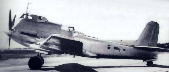
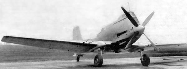
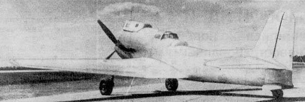
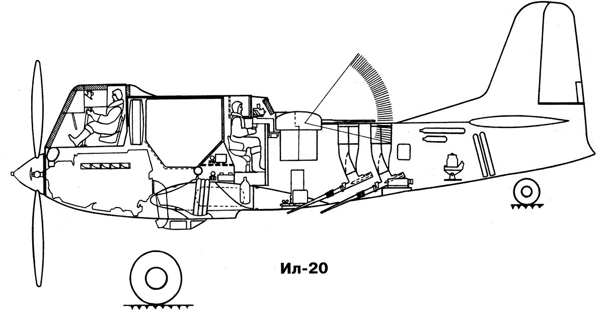
Under the scheme, the first version of the aircraft was a low-winged liquid-cooled engine with a four-blade propeller with a diameter of 4,2 meters. The cockpit was located unusually - directly above the engine - and was pushed forward to the limit. A long windshield of 70-mm thickness, set at an angle of 100 degrees, formed the front of the cab. One end of it almost rested against the bushing of the screw. This provided a forward-downward view in the 37 degrees sector, and when diving at an angle of 40-45 degrees, the pilot could see targets almost directly under the plane. Behind the cockpit were oil and gas tanks. Behind them was the gunner’s cabin, remotely controlling the 23-mm cannon placed in a special IL-VU-11 mobile unit with a hydraulic drive and a mechanism for circling the gun barrel along the fuselage and tail unit contour (in order to protect them from their own weapons).
The installation was designed in the Ilyushin Design Bureau. It provided high angles of fire at the top of the rear hemisphere: 80 degrees - upwards and 90 degrees - right and left. The maximum movement speed of the weapon in the mobile unit was 4-45 degrees / sec. Since the lower quarter of the hemisphere was not protected at all by a cannon mount, an AG-10 aircraft grenade for the 2 was additionally placed at the bottom of the fuselage, thereby organizing partial protection. The tail plumage was single-chin, the wing and horizontal plumage were trapezoid in plan. Water and oil radiators were located in the center section, the engine air intake was located in the lower part of the fuselage, in the area of the front wing trim.
The cockpit of the pilot and gunner, engine, fuel supply and lubrication systems, cooling system were inside the armored box. The total weight of metal armor was 1840 kg, and transparent - 169 kg. The cockpit had, in addition to the frontal, two side armored glass with a thickness of 65 mm and a rear armored glass, also 65-mm. In the upper part of the cabin from the sides of the lantern were armor plates with a thickness of 10 mm; the sides of the cockpit, the rear bulkhead behind the pilot were 10-mm, and in the upper part - 15-mm. The shooter behind and above was protected by 100-mm bulletproof glass, front upper sheet behind the gas tank and onboard 6-mm sheets, lower cabel armor sheet in 8 mm, upper and lower shielded armor 8 + 8 mm thick.
Motor booking included an armored car made of 6,8 and 12 mm thick sheets, which protects it well in front, bottom and sides. The top sheet of the gas tank with a thickness of 4 mm, the side sheets in 6 mm and the plates behind the tank in 10 mm completely covered it from those sides where there was no other armor protection. The radiators were covered from the sides with sheets in 4 mm, a radiator shield inside the motor armor in 6 mm, bottom armor plates 8 mm thick, and two 10 mm radiator armors. As you can see, the reservation was made exceptionally strong. It mainly provided protection against 12,7 mm bullets and, to a significant extent, against 20-mm aviation cannons. Compared to IL-10, the thickness of metal armor increased on average by 46%, and transparent - by 59%. The offensive weapons in the first version included two 23mm caliber wing cannons for firing forward in a dive or planning and two 23-mm cannons mounted in the fuselage at an angle of 22 degrees to the flight line - for firing at a strafing flight. The normal bomb load was 400 kg, while overload was 700 kg. Under the wing in the transshipment version, the suspension of four single-charge jet guns ORO-132 was provided.
In the second offensive version, it was planned to use one 45 caliber mm gun, two 23-mm guns and six ORO-132. The aircraft was equipped with a perfect flight and navigation and radio communications equipment, thermal de-icing system. This expanded the possibilities of its use in bad weather conditions (the main aircraft data corresponding to the TTT obtained in the draft design and the results of factory tests are listed in the 2, 3 and 4 columns of the 2 table). In the conceptual design was developed and the second version of the defensive armament of the aircraft IL-20. There, instead of the upper IL-VU-11 installation, the IL-KU-8 mobile aft gun mount, located in the tail section of the aircraft, was used. It protected the aircraft in the rear hemisphere from enemy fighter attacks from all directions. In the IL-KU-8, the shooter at the rear was protected by bulletproof glass 100 mm thick, from the sides - by bulletproof glass in 65 mm. Curved along the contour of the rifle installation, armor 10 mm thick, side 6-mm and rear 4-mm armor plates provided reliable protection for the shooter in this variant.
Despite a number of original ideas, the draft design of the IL-20 was rejected as inconsistent with the decision of the USSR Council of Ministers and the tactical and technical requirements. From the 2 table it can be seen that this concerned the basic flight data and weapons. The main drawback was the low flight speed of the aircraft, which turned out to be even lower than that of the serial IL-10. Offensive weapons also did not satisfy the customer. A significant increase in the midsection of the fuselage and its lateral surface led to a deterioration in the aerodynamics of the aircraft, an increase in the flight weight, and an increase in the possibility of enemy fire damage. Since the distribution of the armor installed on the aircraft was carried out over a large surface, the experts of the Air Force Scientific Research Institute did not see an improvement in booking compared to the IL-10. Extremely complicated operation of the VMG due to irrational ways of approaching the motor and its units. With all the work related to the shooting of blocks or their covers, it was necessary to disassemble the engine itself from the aircraft. All work on the motor mechanic had to perform in the upside down position. The pilot got into the cockpit only when the engine was not running. At emergency leaving there was a danger of getting under the screw.
It was noted that the fire power of the IL-20 is less than that of the IL-10. At the same time, it was possible to fire only from two cannons - either wing or fuselage. The expediency of applying the latter was not in doubt, but there was a desire to have mobile units. Along the way, we will say that the quite successful developments in this field that were already available at that time by G.M.Mozharovsky and I.V. Venevidova were not used. When loading PTAB, the bomb load was only 300 kg. The main positive factor was an excellent forward-down view (although only in a very narrow sector). The overview to the side and forward was the same as that of the IL-10.
The layout of the IL-20 was presented to the mockup commission in July 1948. The protocol that approved 21 on July 1948 was the Commander-in-Chief of the Air Force, Air Marshal K.A. Vershinin, the engine was already called M-47. The model in the variant with IL-VU-11 was declared incomplete. Browse down - side turned out to be worse than the IL-10. The cab was located too close to the propeller, which is unsafe when it was left, and during an emergency landing, the propeller blades are likely to be damaged by the propeller blades. There was no emergency reset of the flashlight and protective anti-coiling device. The layout scheme complicated operation. Among the positive qualities, there was an excellent forward-down view and the presence of guns firing at an angle downward and making it possible to attack area targets from horizontal flight at altitudes from ramping flight to 700-800 meters. Vershinin did not consider the construction of the IL-20 necessary until the final approval of the layout. However, the aircraft in the first version produced. He had four movable wing cannon X-3 designed by B.G. Shpitalnogo 23-mm caliber with ammunition 900 shells. In the IL-VU-11 mounted mobile gun W-3 with ammunition 200 shells.
Factory tests began on November 20 1948 g. The first flight at the beginning of December 1948 was made by the pilot V.K. Kokkinaki. During the test, the aircraft showed the maximum flight speed of all 515 km / h at an altitude of 2800 meters. Due to low flight data, failure to comply with the requirements for armament and the lack of knowledge of the M-47 engine designed by M.R. Flissky for IL-20 in accordance with the Resolution of the Council of Ministers of the USSR 14, 1949 was stopped in May. The plane was examined by the deputy commander for combat training and noted the following shortcomings:
- cockpit pilot and gunner split fuel tank;
- no dive issues worked out;
- not ensured the effectiveness of extinguishing a fire in the area of the gas tank;
- set four guns ahead instead of six, and others.
S.V. Ilyushin worked through two more (except for those already considered by us) variants of IL-20, with an IL-10 type arrangement. Flight data was obtained, of course, higher.
In March, the 1948 of Mr. S.M. Alekseev presented a draft design of an armored two-seater attack aircraft, the W-218 with a powerful X-shaped M-251 motor. The plane was not included in the pilot construction plan for 1949. The model was built, but due to the elimination of the OKB-21, work on the aircraft stopped. CM. Alekseev addressed 19 in February 1951 with a letter to the Air Force and asked him to return to the draft. The chairman of the Air Force Scientific and Technical Complex, B.N. Ponomarev, considered that building the X-218 was not feasible due to the fact that his flight data was worse than that of IL-10 (see the 5 and 6 column of the 2 table). It was noted the absence of bombs (only in the transshipment variant), weak booking, the impossibility of disassembling the aircraft for its transportation. But on the gun-and rocket weapons, as well as the range of flight W-218 superior IL-10. One would expect that his climb rate would also be better.
According to the layout scheme, the aircraft resembled the BS-MB AM-38. The forward-downward survey was about 15 degrees. The presence of well-developed ejection seats by this time solved the problem of the pilot leaving the car safely. The wing was swept with 16╟ along the leading edge, the rear one was straight. Steering and aileron control was carried out by means of separate systems - right and left, so that if one of them was damaged or failed, control of the aircraft was maintained. The W-218 differed from the BSH-MV in two remotely controlled side turrets with 20-mm caliber cannons with 240 ammunition. This ensured the defense capability of the aircraft, although some questions remained regarding its operation. The offensive weaponry included four 15 caliber 23 mm cannons with 480 ammunition rejected by 132. The beams housed three ORO-XNUMX jet guns. In connection with the use of a powerful engine, two coaxial screws were installed, and a version of the aircraft with a conventional chassis was also developed.
S.M. Alekseev also designed an armored attack aircraft, the W-218, with an even more exotic layout, which provided for the motor to be placed in the tail section of a conventional fuselage, and the pusher propeller - behind the tail unit. It is known that this scheme of practical application was not found due to the inability to ensure safety when landing at high angles of attack and during ground operation. Thus, a fairly good overview of the forward-downing could not be obtained from serial single-engine attack aircraft. Perhaps the most successful solution should be the one proposed in the project of OPB AM-37 S.А. Kocherigin. The designer, using the traditional layout scheme, managed to achieve a forward-downward view required by the attack aircraft, while at the same time solving the problem of providing a downward view for the aircraft that a bomber needs. An excellent review ahead - down made in the IL-20 M-47, but at the cost of a loss in many other parameters, which did not allow the car to be accepted into the series. It can be concluded: the hope to solve the problem of forward-downward visibility due to unconventional layouts of single-engine attack aircraft did not materialize.
LTH:
Modification IL-20
Wingspan, m 17.00
Length of aircraft, m 12.59
Height, m
Wing area, m2 44.00
Weight, kg
empty 7535 aircraft
normal takeoff 9500
maximum take-off 9780
Engine type 1 PD M-47
Power, hp
take-off 1 x 3000
nominal 1 x 2300
flight 1 x 2400
Maximum speed km / h
off the ground xnumx
at height 515
Ferry range, km 1700
Practical range, km 1045
Rate of climb, m / s 375
Practical ceiling, m 7750
Crew 2
Armament: one 23 mm NA-23 cannon, two 23 mm NS-23 cannons
normal bomb load - 1190 kg,
with bombs up to 500 kg on an external suspension.
under consoles - 8 PC-82 or 4 PC-132.
Creating the Su-6, to get a more or less satisfactory view ahead - down, P.O. Sukhoi spent a long time looking for a place under the engine and carefully chose the engine hoods. On this machine, the optimal solution was found. On the FW-190F aircraft, even in the version with a slightly raised pilot seat, the forward-down view was almost absent. S.V. Ilyushin to improve visibility on BSH-2 (IL-2) was forced to raise the seat of the pilot, lower the engine relative to the axis of the aircraft, pay much attention to the contours of the engine hood. As a result, he provided a forward-downward viewing angle of about 8 degrees, which was considered acceptable (although a value equal to 30-35 degrees would be desirable).
All serial attack aircraft did not have a review down under the plane. The exception was IL-2, equipped with a special periscope, which, however, did not receive further distribution. The way out was found using the time delay for dropping bombs, either with the help of special sights and temporary mechanisms, or by marking marks on the structural elements of the aircraft. Sometimes, in order to increase the effectiveness of the Il-2 aircraft from a strafing flight, it was necessary to make them “sighted” with the help of target airplanes for attack aircraft (STSUS). In this capacity, flight and search targets at medium altitudes of the SS, Pe-2, and subsequently - specially selected IL-2 crews were used. After the discovery of the object of attack, the navigator or pilot STSUS dropped bombs and thereby designated it.
At the end of 1940, designer S.А. Kocherigin presented to NCAA a draft design of a multipurpose single-seat OPB battlefield aircraft with an AM-37 engine (including an attack aircraft), in which he consciously went for some deterioration in aerodynamics. To ensure a good (up to 15 degrees) forward-down view, it provided for a high placement of the pilot with a corresponding increase in the size of the cockpit canopy. In addition, a special glazing was developed for the cockpit floor and the manhole covers under it, which gave an additional view of the area directly under the aircraft.
The new machine was the development of the previously designed and under construction single-engine bomber OPB M-90 and according to the scheme it was a mid-wing with a “reverse seagull” wing, with a normal-type tail unit. Chassis with tail wheel, retractable, mixed design. The middle part of the wing was a center section connected to the fuselage. Consoles had a production connector at the turn of the "seagull". When transporting the weaning of the wing was carried out at the fuselage. The wing is metallic, single-spar, with a working casing (steel spar). Profiles open. Ribs are duralumin, stamped. A relatively thick, trapezoidal wing in plan with rounded ends, with well-developed mechanization — automatic slats, hovering ailerons and flaps. NASA-230 wing profile. The thickness along the axis of the aircraft is 19%, by fracture - 16%, at the ends - 7%.
The front part of the fuselage is duralumin, the tail part is made of wood. The fuselage section is elliptical. The lantern is made of plexiglass, its emergency discharge was provided. The pilot's seat at the back and bottom was covered with 13 mm thick armor, which protects against 12,7 mm bullets and shells aviation guns. It was also supposed to put an armored visor. The keel was made in one piece with the fuselage. The rudder and horizontal tail are duralumin, sheathed with canvas. The rudders had weight and aerodynamic compensation. The chassis was hydraulically retracted, emergency release was performed by an air system. The main brake wheels were retracted into the wing to the fuselage, the tail wheel - into the aft fuselage. Under the cockpit floor, a mine was provided for bombs with a caliber of up to 500 kg.
Steering and aileron rigid, with ball bearings. Trimmers piloted. Three-bladed screw. Two water radiators were located under the center section, one - in the sock of the motor. The oil radiator was also wearing an engine sock. There were four fuel tanks with a total capacity of 510 liters. Instead of a bomb, an extra 500-liter gas tank could be placed in the bomb bay. In the engine nacelle above the engine blocks there was an oil tank of 70 liters. On the sides of the engine were two exhaust manifolds. The outdoor antenna was a three-beam.
The aircraft's armament consisted of two synchronous BSs and two synchronous ShKAS with 400 and 1500 rounds of ammunition, respectively. Machine guns were placed on a special farm on a motor frame: on the right - ShKAS, on the left - BS. In the overload under the wing could fit two guns caliber 20-23 mm. Provided for the use of three bomb racks that provided dive-bombing. In the fuselage bomb bay on the parallelogram one of the following types of bombs could be suspended: FAB-500, BRAB-500, FAB-250, BRAB-200, BETAB-150. For aiming provided sight PB-3. Under the wing, the aircraft could carry bombs with a caliber of 100 and 250 kg for dive bombing, which was carried out with the help of a PBP-1 sight (it was also used when firing machine guns). If necessary, it was possible to place three PO-82 guns with PC-82 rocket projectiles on the fuselage bomber holder.
The draft design was considered by the NCAP commission chaired by Academician B.N. Yuriev, with the participation of BCPyshnova and V.Polikovsky. The preliminary examination was conducted by the secretary of the commission Mashkevich. The result of their work was the conclusion that the flight characteristics are real, with the exception of the flight range - the designer did not have absolutely accurate data on specific engine consumption. The modification under AM-37 was recognized as expedient in the presence of positive results on testing the first OPB version with M-90. The protocol of the commission from January 23 1941 was approved by the Deputy People's Commissar of the aviation industry A.S. Yakovlev. At the beginning of 1941, S.O. Kocherigin sent the project OPB AM-37 to the Air Force Scientific Research Institute. The conclusion on it was approved 12 February 1941 g. Very high flight data specialists of the Research Institute of the Air Force considered quite realistic, noting that the aircraft compares favorably in the review, and will have the necessary stability. The draft design was approved and approved as the 2-th copy of the OPB plane under construction on the Resolution of the NCO of 7 in August 1940. It was proposed to force the construction of a machine with M-90 or M-89 engines and to provide Kocherigin with an independent production base for this.
Experts NII Air Force have contributed to the improvement of the aircraft. They proposed to increase the size of the tail wheel to 400x150 mm; make the lamp moving back, and the stabilizer - adjustable; somewhat reduce the area of vertical and horizontal tail; machine guns to place symmetrically, increase the ammunition of the BS to 500 cartridges; add wing guns; for a dive option, develop air brakes and provide a dive-out machine. We also recommended to consider the installation of AM-38 (in the 2 column of the 1 table, flight data of OPB with the AM-38 motor, obtained by us from the results of approximate calculations) are given. The plane, having booked a pilot only from behind and from below, would be close in speed to the IL-10 aircraft. And in terms of maneuverability, visibility, the maximum caliber of bombs, ensuring dive bombing would surpass it. We made a calculation of the flight data of the OPB and with the AM-42 motor, but on condition that 900 kg of armor will be added (see the 3 column of the 1 table). The flight speed turned out to be close to IL-10 while maintaining the advantages noted above.
The load on the wing would be too large, but given its powerful mechanization and the positive influence of the “return gull”, one would expect good maneuverability and takeoff and landing characteristics. The results of calculations confirm that the project deserved attention and had development prospects. Due to the lack of a finished engine, the built OPB M-90 was not tested for a long time. Then it was redesigned for M-89, installed the engine and began flight tests of the first instance of the aircraft. But M-89 was also not brought. Motor AM-37 has already been removed from mass production. In the documents there is information that they built both copies of the aircraft OPB, and that there was a plan to put on them the engine M-71, which also was not realized. Kocherigin did not dare to use the M-82, realizing that the flight data of the machine would be much lower. And lost. The production base of plant No. 156 was overloaded and as soon as the designer had a hitch, in the second half of 1942 he was forced out to a very honorable and responsible post of the chief editor of BNT TsAGI. It seemed that the most radical solution to the problem of providing a forward-down view was only using unconventional aircraft layout schemes.

The first such solution was a two-beam scheme with a fuselage-gondola, in the rear of which was placed the motor with a pushing screw. The project of an armored attack aircraft BS-MW AM-38 was developed by A.A. Arkhangelsky, G.M. Mozharovsky and I.V. Venevidov at the end of 1940. The idea of creating the aircraft belongs to Mozharovsky and Venevidov - designers of the plant №32, the authors of a number of developments, related to armaments: rifle turrets, sights, bomber armaments, combined rifle-gun installations for attack aircraft with weapons, shooting at an angle down from the axis of the KABV aircraft (combined artillery-bomber armament). To do this, they experimented with their KABV installations on SB 2М-103А, Yak-2 2М-103 airplanes and concluded that a special attack aircraft was needed, the basis of which offensive armament would be their combined cannon-gun installation. Offered and scheme of the machine. But, not having sufficient experience in this matter, the preliminary design did not work thoroughly. In particular, at that time it was believed that they chose too much load on the wing for attack aircraft (we note that later on all constructed armored attack aircraft it turned out to be about the same).
Designer A.A. Archangel and laid on him the leadership of the work. Here, the review problem was solved quite successfully (a forward-downward angle of about 15 degrees was provided), but there were difficulties of a different kind related to the pilot leaving the plane safely in flight and providing fire protection for the rear hemisphere. Operation of the aircraft with a propeller placed in the tail also required clear and clear recommendations from the designers. The BS-MV AM-38 draft design was presented to 29 December 1940, additional materials - January 25 1941. The draft design statement was approved by 12 March 1941, the head of the Air Force Scientific Research Institute A.I. Owl. The aircraft consisted of a single-engine single-engine monoplane with a two-beam scheme with a pilot's cabin, an AM-38 engine and armament (located in the gondola fuselage), a pushing propeller, a return-type wing, a retractable landing gear with a nose wheel.
The fuselage is armored, with a power transverse and longitudinal set. Armor cemented plates were the strength of the design elements. Aerodynamic forms in the nose and tail of the fuselage were formed by duralumin lining attached to armor plates - in the middle part of the fuselage, these plates were directly its surface, mating with the nose and rear parts of the fuselage. On the canopy of the lantern, on the sides of the pilot's head, as well as at his feet, transparent armor was placed. As well as on OPB AM-37 S.А. Kocheriigina, it was envisaged to provide a downward view directly under the aircraft, which made it possible to more effectively use KABV. The total weight of the armor was 845 kg, it defended the pilot himself, the engine, the gasoline and oil tanks, the radiators and all the equipment in the pilot's cabin.
Wing two-spar, all-metal. Spars, ribs and trim duralumin. The center section was one with the fuselage. Detachable console trapezoid in plan, with rounding. On the whole span of the center section and on the consoles of the Shrenka shields. The ailerons of the type "Fraze" during take-off and landing worked synchronously with the shields. Opposite the ailerons were automatic slats. NASA-23012 wing profile. The tail beams had a longitudinal and transverse set. Stringers, ribs and working trim - duralumin. The beams were rigidly attached to the reinforced ribs of the center section. The volume of the beams was used to be placed when the main wheels of the chassis were cleaned back, and the ends of the beams were used as reserve tail wheels (to protect the tail section when landing with a large angle of attack).
The tail plumage was metallic. Keels are made as one unit with tail beams. On the handlebars trimmers. The steering wheels are statically and dynamically balanced, the control is rigid, duplicated. The nose wheel was retracted back into the fuselage, under the cockpit. The main wheels on two racks. Cleaning and release of the chassis using a hydraulic drive. The armor plates of the rear fuselage served as an engine frame. Screw series ZSMV-2, diameter 3,2 meter. Behind the cockpit, a KABV was installed with Taubin’s 30-mm caliber guns with 23 projectile and 162 XKUM machine guns with 4 ammunition that could be deflected to 3000 degrees. Control by electric motor. The sight was synchronously connected with small arms and guns. The consoles provided for the suspension of six PC-82 rockets. Bomb holders were placed inside and outside the center section. Inside, there was a suspension of two bombs FAB-100, or four FAB-50, or six AO-25, or six AO-20, or one hundred forty-four AO-2,5, or boxes and tapes for ampoules and small-caliber bombs; outside - two FAB-250, two FAB-100, two FAB-50, four AO-25, four AO-20. The normal bomb load was 250 kg, while overload was 500 kg. Between the cartridge boxes and the motor AM-38 in the central part of the fuselage was located the fuel tank on the 930 l (700 kg), underneath the oil tank with a capacity of 70 liters. The water radiator was under the wing. Provided a fan for blowing the engine under the hood.
The final conclusions of the commission considered the draft said that the sustainability reserves are insufficient, but the aircraft layout is of some interest. The main advantage was considered an excellent review of the pilot, reaching 48% of the entire sphere. Strangely enough, the experts of the scientific research institute of the Air Force initially called in the KABV. The following wishes were put forward as the main ones: the attack aircraft must take at least 400 kg of bombs, mostly of small caliber; you must put a gun caliber 37 mm; add machine guns caliber 12,7 mm; to reduce the specific load on the wing, simplifying take-off and landing - the aircraft is massive and the quality of training of wartime pilots will be low; connect to the design of a powerful aircraft crew.
In general, the draft design approved. The plane was supposed to be unusually strong weapons, and only a misunderstanding of the advantages of KABV caused the desire to correct it. The construction of the BS-MV AM-38 was carried out in accordance with the Decree of the SNK of the USSR and the Central Committee of the CPSU (b) of 25 March 1941, which contained a requirement to ensure maximum flight speed 470 km / h and a normal bomb load of at least 500-600 kg.
IL-2 and IL-20 viewing angle
In March, 1941 was presented a model of the aircraft, consisting of a fuselage with a center section and landing gear, a cockpit, a combined mobile rifle installation KABV with four ShVAK cannons and four ShKAS machine guns. The stated maximum speed was 420 km / h (apparently, corrected after additional calculations by AA Arkhangelsky). Normal bomb load 200 - 250 kg, overload - 400-500 kg. The mockup commission recommended increasing the thickness of the armor from 6 to 10 mm, and protecting the fuselage tank with bottoming 13-mm armor. The final Act noted that the layout could not be approved due to non-compliance with tactical and technical requirements. However, the Combined Artillery Battery BS-MB system was of interest to the Air Force, therefore they recognized it expedient to bring to the attention of the government the question of the need to revise the assigned TTT and aircraft layout (the Air Force experts apparently realized that the KABM contained the main highlight of the BS-MV AM-38 project ). The protocol on the layout was approved by 23 on June 1941. Deputy Head of the Main Directorate of the Air Force. By this time, the construction of the aircraft had already begun at the plant number XXUMX. The war forced to curtail work on the BS-MB.
S.V. Ilyushin sent 22 July 1942 to the address of the Chief Air Force Engineer A.K. Repina conceptual design of a single-engine single armored MS attack aircraft with an AM-38 engine. In the accompanying letter, he reported: “The draft of the pilot construction plan for 1942 included a twin-engine armored attack plane proposed by me (meaning IL-6 aircraft - author). Taking into account the current situation and the difficulties of implementing this type of aircraft, the proposal for which I am filing, I represent a single-engine, development of the Il-2. " And then he lists the features of his new car:
radically changed the review, which is crucial for attack aircraft;
artillery armament was strengthened - a 37-mm caliber gun will allow hitting heavy Tanks (strictly speaking, only light and medium tanks - auth.);
artillery and small arms are concentrated in one place, which improves the sighting and accuracy of shooting;
minimum armor thickness increased from 4 to 5 mm;
reduced drag;
Changed landing gear, etc.
The aircraft requires a motor with an extended shaft. Provides two options for weapons. Bombing gun-shooting: normal variant bomb load - to 400 kg (16x25 kg or 40x10 kg or 160x2,5 kg), two synchronous ShVAK gun with ammunition 200 shells, two synchronous ShKAS gun with ammunition cartridges 1500. Gun-gun variant: one gun B.G.Shpitalnogo ShFK-37 with the barrel and 40 ammunition shells passed through the gearbox into the hollow shaft of the screw, two ShVAK ammunition with 200 ammunition, SHKAS synchronous machine guns with 1500 ammunition with ammunition.
Under the scheme, the aircraft MSh AM-38 (modernized attack aircraft with the engine AM-38) resembled the R-39 "Aerocobra". But the chassis was designed not with the nose, but with the usual tail wheel. It is known that Bell (designer of the aircraft P-39) chose the scheme of his aircraft, based on such considerations as the need to ensure the effectiveness of weapons and ease of landing for the pilots (tired after air combat), which was facilitated by a good forward-down view. It is also known that the Americans did not have motor cannons and they did not work out the versions of synchronous guns, in connection with which the main weapon of the fighters was large-caliber wing machine guns. Among the shortcomings of the armament scheme used by the Americans are the low accuracy of fire, which the P-39 was able to improve by positioning the weapon more compactly. And including the M-4 gun caliber 37 mm.
In the proposed car Ilyushin placed the motor AM-38 approximately in the center of gravity of the aircraft. Power transfer to the propeller was carried out using an elongated shaft, held under the armored floor of the cockpit. The air intake of the engine was located at the top of the fuselage. The cab was pushed forward, which provided a forward-downward view to 24 degrees. Under the cockpit of the pilot housed a compartment of small arms and guns. The gas tank and oil tank were located between the cabin and the engine in the upper part of the fuselage. Water and oil radiators of the cooling system and lubrication of the motor were installed in the ventral part of the center section; they were cooled by outside air fed through curved channels from the air inlets at the toe of the wing at the right and left sides of the fuselage. The bombs, as in the IL-2, were placed inside the center plan bombs and in the overload - additionally on external hangers.
At the chassis, the main wheels were retracted by flying to the center section with the wheels turning in the process of cleaning approximately 90 degrees (later this idea was implemented on the IL-10). Retractable was the tail wheel. The use of a wing with a sweep on the leading edge of 15 degrees made it possible to achieve the necessary range of operational alignments. The reservation of the pilot, gasoline and oil tanks, water and oil radiators was provided by an armored hull of a very complex shape, mainly with rectangular generators. This simplified its manufacturing technology, but at the same time increased the vulnerability of armor. The Air Force Research Institute gave a positive opinion on the project, only recommended replacing the ShVAK guns with WYa-23.
It should be noted that the mass of the empty aircraft and takeoff increased compared with the IL-2. And despite some improvement in aerodynamics, the aircraft with the AM-38 engine showed insufficiently high flight data. In addition, there was a need for a double attack aircraft, and in the framework of the adopted layout scheme it was impossible to carry out such a task. In addition, the experience of creating Bell-type Р-39 and Р-63 aircraft of the same type found two inherent chronic drawbacks that are hard to get rid of: destruction of a long shaft for the propeller due to torsional vibrations and poor counter-stomping properties. Hence the decision - not to build an MSh-AM-38 aircraft.
In accordance with the Decree of the USSR Council of Ministers on March 13, 11 on the OKB S.V. Ilyushin was given the task of creating a new attack aircraft with slightly higher (compared to the IL-1947) flight data, more powerful cannon and rocket weapons, improved visibility and reservation. At the end of 10, the designers completed the development of a single-engine armored two-seater attack aircraft with a liquid cooling engine MF-1947ш. The original layout was used, which provided an excellent forward-down view. Unusual and gun armament. The draft design of the IL-45 MF-20 aircraft was sent in February to 45 at the Air Force Research Institute.
The USSR Council of Ministers decree on the construction of prototypes of the Il-20 was adopted on 12 on June 1948. Markov. Major engineer SGFrolov was appointed responsible for the aircraft. The purpose of the attack aircraft was formulated as follows: "To suppress and destroy manpower and technical equipment on the battlefield and in the tactical depth of the enemy's position." It was proposed to make two projects with different variants of offensive and defensive weapons.
Under the scheme, the first version of the aircraft was a low-winged liquid-cooled engine with a four-blade propeller with a diameter of 4,2 meters. The cockpit was located unusually - directly above the engine - and was pushed forward to the limit. A long windshield of 70-mm thickness, set at an angle of 100 degrees, formed the front of the cab. One end of it almost rested against the bushing of the screw. This provided a forward-downward view in the 37 degrees sector, and when diving at an angle of 40-45 degrees, the pilot could see targets almost directly under the plane. Behind the cockpit were oil and gas tanks. Behind them was the gunner’s cabin, remotely controlling the 23-mm cannon placed in a special IL-VU-11 mobile unit with a hydraulic drive and a mechanism for circling the gun barrel along the fuselage and tail unit contour (in order to protect them from their own weapons).
The installation was designed in the Ilyushin Design Bureau. It provided high angles of fire at the top of the rear hemisphere: 80 degrees - upwards and 90 degrees - right and left. The maximum movement speed of the weapon in the mobile unit was 4-45 degrees / sec. Since the lower quarter of the hemisphere was not protected at all by a cannon mount, an AG-10 aircraft grenade for the 2 was additionally placed at the bottom of the fuselage, thereby organizing partial protection. The tail plumage was single-chin, the wing and horizontal plumage were trapezoid in plan. Water and oil radiators were located in the center section, the engine air intake was located in the lower part of the fuselage, in the area of the front wing trim.
The cockpit of the pilot and gunner, engine, fuel supply and lubrication systems, cooling system were inside the armored box. The total weight of metal armor was 1840 kg, and transparent - 169 kg. The cockpit had, in addition to the frontal, two side armored glass with a thickness of 65 mm and a rear armored glass, also 65-mm. In the upper part of the cabin from the sides of the lantern were armor plates with a thickness of 10 mm; the sides of the cockpit, the rear bulkhead behind the pilot were 10-mm, and in the upper part - 15-mm. The shooter behind and above was protected by 100-mm bulletproof glass, front upper sheet behind the gas tank and onboard 6-mm sheets, lower cabel armor sheet in 8 mm, upper and lower shielded armor 8 + 8 mm thick.
Motor booking included an armored car made of 6,8 and 12 mm thick sheets, which protects it well in front, bottom and sides. The top sheet of the gas tank with a thickness of 4 mm, the side sheets in 6 mm and the plates behind the tank in 10 mm completely covered it from those sides where there was no other armor protection. The radiators were covered from the sides with sheets in 4 mm, a radiator shield inside the motor armor in 6 mm, bottom armor plates 8 mm thick, and two 10 mm radiator armors. As you can see, the reservation was made exceptionally strong. It mainly provided protection against 12,7 mm bullets and, to a significant extent, against 20-mm aviation cannons. Compared to IL-10, the thickness of metal armor increased on average by 46%, and transparent - by 59%. The offensive weapons in the first version included two 23mm caliber wing cannons for firing forward in a dive or planning and two 23-mm cannons mounted in the fuselage at an angle of 22 degrees to the flight line - for firing at a strafing flight. The normal bomb load was 400 kg, while overload was 700 kg. Under the wing in the transshipment version, the suspension of four single-charge jet guns ORO-132 was provided.
In the second offensive version, it was planned to use one 45 caliber mm gun, two 23-mm guns and six ORO-132. The aircraft was equipped with a perfect flight and navigation and radio communications equipment, thermal de-icing system. This expanded the possibilities of its use in bad weather conditions (the main aircraft data corresponding to the TTT obtained in the draft design and the results of factory tests are listed in the 2, 3 and 4 columns of the 2 table). In the conceptual design was developed and the second version of the defensive armament of the aircraft IL-20. There, instead of the upper IL-VU-11 installation, the IL-KU-8 mobile aft gun mount, located in the tail section of the aircraft, was used. It protected the aircraft in the rear hemisphere from enemy fighter attacks from all directions. In the IL-KU-8, the shooter at the rear was protected by bulletproof glass 100 mm thick, from the sides - by bulletproof glass in 65 mm. Curved along the contour of the rifle installation, armor 10 mm thick, side 6-mm and rear 4-mm armor plates provided reliable protection for the shooter in this variant.
Despite a number of original ideas, the draft design of the IL-20 was rejected as inconsistent with the decision of the USSR Council of Ministers and the tactical and technical requirements. From the 2 table it can be seen that this concerned the basic flight data and weapons. The main drawback was the low flight speed of the aircraft, which turned out to be even lower than that of the serial IL-10. Offensive weapons also did not satisfy the customer. A significant increase in the midsection of the fuselage and its lateral surface led to a deterioration in the aerodynamics of the aircraft, an increase in the flight weight, and an increase in the possibility of enemy fire damage. Since the distribution of the armor installed on the aircraft was carried out over a large surface, the experts of the Air Force Scientific Research Institute did not see an improvement in booking compared to the IL-10. Extremely complicated operation of the VMG due to irrational ways of approaching the motor and its units. With all the work related to the shooting of blocks or their covers, it was necessary to disassemble the engine itself from the aircraft. All work on the motor mechanic had to perform in the upside down position. The pilot got into the cockpit only when the engine was not running. At emergency leaving there was a danger of getting under the screw.
It was noted that the fire power of the IL-20 is less than that of the IL-10. At the same time, it was possible to fire only from two cannons - either wing or fuselage. The expediency of applying the latter was not in doubt, but there was a desire to have mobile units. Along the way, we will say that the quite successful developments in this field that were already available at that time by G.M.Mozharovsky and I.V. Venevidova were not used. When loading PTAB, the bomb load was only 300 kg. The main positive factor was an excellent forward-down view (although only in a very narrow sector). The overview to the side and forward was the same as that of the IL-10.
The layout of the IL-20 was presented to the mockup commission in July 1948. The protocol that approved 21 on July 1948 was the Commander-in-Chief of the Air Force, Air Marshal K.A. Vershinin, the engine was already called M-47. The model in the variant with IL-VU-11 was declared incomplete. Browse down - side turned out to be worse than the IL-10. The cab was located too close to the propeller, which is unsafe when it was left, and during an emergency landing, the propeller blades are likely to be damaged by the propeller blades. There was no emergency reset of the flashlight and protective anti-coiling device. The layout scheme complicated operation. Among the positive qualities, there was an excellent forward-down view and the presence of guns firing at an angle downward and making it possible to attack area targets from horizontal flight at altitudes from ramping flight to 700-800 meters. Vershinin did not consider the construction of the IL-20 necessary until the final approval of the layout. However, the aircraft in the first version produced. He had four movable wing cannon X-3 designed by B.G. Shpitalnogo 23-mm caliber with ammunition 900 shells. In the IL-VU-11 mounted mobile gun W-3 with ammunition 200 shells.
Factory tests began on November 20 1948 g. The first flight at the beginning of December 1948 was made by the pilot V.K. Kokkinaki. During the test, the aircraft showed the maximum flight speed of all 515 km / h at an altitude of 2800 meters. Due to low flight data, failure to comply with the requirements for armament and the lack of knowledge of the M-47 engine designed by M.R. Flissky for IL-20 in accordance with the Resolution of the Council of Ministers of the USSR 14, 1949 was stopped in May. The plane was examined by the deputy commander for combat training and noted the following shortcomings:
- cockpit pilot and gunner split fuel tank;
- no dive issues worked out;
- not ensured the effectiveness of extinguishing a fire in the area of the gas tank;
- set four guns ahead instead of six, and others.
S.V. Ilyushin worked through two more (except for those already considered by us) variants of IL-20, with an IL-10 type arrangement. Flight data was obtained, of course, higher.
In March, the 1948 of Mr. S.M. Alekseev presented a draft design of an armored two-seater attack aircraft, the W-218 with a powerful X-shaped M-251 motor. The plane was not included in the pilot construction plan for 1949. The model was built, but due to the elimination of the OKB-21, work on the aircraft stopped. CM. Alekseev addressed 19 in February 1951 with a letter to the Air Force and asked him to return to the draft. The chairman of the Air Force Scientific and Technical Complex, B.N. Ponomarev, considered that building the X-218 was not feasible due to the fact that his flight data was worse than that of IL-10 (see the 5 and 6 column of the 2 table). It was noted the absence of bombs (only in the transshipment variant), weak booking, the impossibility of disassembling the aircraft for its transportation. But on the gun-and rocket weapons, as well as the range of flight W-218 superior IL-10. One would expect that his climb rate would also be better.
According to the layout scheme, the aircraft resembled the BS-MB AM-38. The forward-downward survey was about 15 degrees. The presence of well-developed ejection seats by this time solved the problem of the pilot leaving the car safely. The wing was swept with 16╟ along the leading edge, the rear one was straight. Steering and aileron control was carried out by means of separate systems - right and left, so that if one of them was damaged or failed, control of the aircraft was maintained. The W-218 differed from the BSH-MV in two remotely controlled side turrets with 20-mm caliber cannons with 240 ammunition. This ensured the defense capability of the aircraft, although some questions remained regarding its operation. The offensive weaponry included four 15 caliber 23 mm cannons with 480 ammunition rejected by 132. The beams housed three ORO-XNUMX jet guns. In connection with the use of a powerful engine, two coaxial screws were installed, and a version of the aircraft with a conventional chassis was also developed.
S.M. Alekseev also designed an armored attack aircraft, the W-218, with an even more exotic layout, which provided for the motor to be placed in the tail section of a conventional fuselage, and the pusher propeller - behind the tail unit. It is known that this scheme of practical application was not found due to the inability to ensure safety when landing at high angles of attack and during ground operation. Thus, a fairly good overview of the forward-downing could not be obtained from serial single-engine attack aircraft. Perhaps the most successful solution should be the one proposed in the project of OPB AM-37 S.А. Kocherigin. The designer, using the traditional layout scheme, managed to achieve a forward-downward view required by the attack aircraft, while at the same time solving the problem of providing a downward view for the aircraft that a bomber needs. An excellent review ahead - down made in the IL-20 M-47, but at the cost of a loss in many other parameters, which did not allow the car to be accepted into the series. It can be concluded: the hope to solve the problem of forward-downward visibility due to unconventional layouts of single-engine attack aircraft did not materialize.
LTH:
Modification IL-20
Wingspan, m 17.00
Length of aircraft, m 12.59
Height, m
Wing area, m2 44.00
Weight, kg
empty 7535 aircraft
normal takeoff 9500
maximum take-off 9780
Engine type 1 PD M-47
Power, hp
take-off 1 x 3000
nominal 1 x 2300
flight 1 x 2400
Maximum speed km / h
off the ground xnumx
at height 515
Ferry range, km 1700
Practical range, km 1045
Rate of climb, m / s 375
Practical ceiling, m 7750
Crew 2
Armament: one 23 mm NA-23 cannon, two 23 mm NS-23 cannons
normal bomb load - 1190 kg,
with bombs up to 500 kg on an external suspension.
under consoles - 8 PC-82 or 4 PC-132.
Information