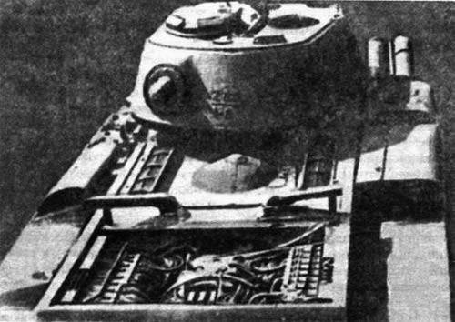
Soviet experimental heavy tank EKV
At the end of 1944, through the joint efforts of the Stalin Military Academy of Mechanization and Motorization, factories No. 627, ChKZ, Elektrosila and Dynamo, on the basis of a decree of the Central Committee of the All-Union Communist Party of Bolsheviks and the SNK of 07.04.1941/1940/XNUMX, an ECV tank was manufactured. The development of electromechanical transmission began in October XNUMX at the VAMM RKKA. The head of the department supervised the work tanks First-level military engineer Gruzdev N.I.
The use of electromechanical transmission on the tank made it possible to: reduce fuel consumption; improve traction characteristics; improve tank agility due to continuous regulation of the speed difference between the tracks, as well as improved braking performance due to electrodynamic braking.
Those. The design of the EKV tank was carried out in September of 1941 of the year, and the Dynamo plant began to manufacture electrical transmission units. Due to the redeployment of the academy and the evacuation of the factories, work on the creation of tank transmission units was delayed, and by January 1943, only 60% had been completed for the total amount of work. In February, 1943, the completion of the work was transferred to plant number 627 in Moscow.
In November-December, the 1944 of the year tested the prototype tank EKV at a research test site. Due to structural deficiencies, the EKV tank was not adopted by the Red Army, however, the experience gained during its development was later used in the design of electromechanical transmissions of the EC-6 and EC-7 heavy tanks.
The serial tank KV-1 of model 1941 of the year was used as a base for the manufacture of an ECV tank. The main differences from the base model consisted in the installation of an electromechanical transmission (on the KV-1 there was a mechanical one), as well as a turret with weapons (the same design was used on the KV-1С tank). The overall layout of the car had a classic scheme.
The driver’s seat as well as the radio operator were located in the control compartment. Also in the control department, in addition to the tank motion control drives, control devices, batteries, a DT machine gun, air tanks, a radio station, part of the spare parts kit and ammunition were placed. In the middle of the frontal armor plate of the hull there was a viewing hatch of the driver, which was closed with an armored lid with a viewing slot with triplex. A mirror-viewing device was installed in the hull roof to the right of the driver. In the frontal list in front of the gunner-radio operator there was a ball bearing for mounting a frontal machine gun. The entrance and exit of the crew members, which were located in the department of control, above the workplace of the radio operator in the roof of the vehicle's hull, was completed with a hatch that was closed with a folding armored cover on the inside loop. In the bottom of the case behind the driver's seat there was a spare hatch for exit.
The fighting compartment was located in the turret and the middle part of the tank hull. In the tower, which was installed on a ball bearing, mounted gun, machine guns, and also housed part of the ammunition. The control compartment housed: one after the other to the left of the gun the gunner of the gun and the tank commander, the loader - to the right of the gun. The seats of the commander, loader and gunner were attached to the tower. They rotated with her. On the roof of the tower above the commander's workplace, a fixed commander's cupola was installed, having five periscope viewing instruments located along its perimeter. In the roof of the tower, in the forward loader and on the stern of the tank, two mirror viewing instruments were mounted. In the roof of the tower to the right of the commander's turret there was an access hatch, which was closed with an armored lid on the hinge. The fuel and oil tanks were installed along the sides of the fighting compartment, on the bottom there was a rotating contact device and the main part of the ammunition.
Behind the fighting compartment was located the engine compartment. The branches were separated by a partition. The engine was installed on the sub-frame in the engine compartment along the longitudinal axis of the machine, alongside the oil and water radiators and two combined air purifiers.
In the stern of the tank was the transmission compartment, which was separated from the engine compartment. It housed the units of electric transmission and control equipment.
Bronezashita tank - protivosnaryadnaya, differentiated. The hull design of an EVA tank did not differ from the hull design of the KV-1 1941 model of the year. The exception was the roof over the transmission compartment, the manhole covers changes in which were made in connection with the installation of electrical transmission units and assemblies, as well as side plates in connection with the installation of new side gearboxes. In addition, the design of protective armor caps of engine exhaust manifolds was changed. Armor caps had a more elongated shape in comparison with similar parts of the KV-1 tank model 1941 of the year. The design of the tower is fully repeated the design of the tower KV-1С. On the tower there were no handrails for tank assault. A tetrachloric hand-held fire extinguisher was used to extinguish the fire.
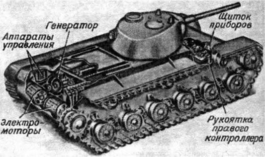
Placement of electromechanical transmission units in an EKV tank
The structure of the electromechanical transmission included a DK-502B starter-generator permanently connected to the B-2K diesel engine by means of clutches, two DK-301B traction electric motors, two onboard gearboxes and control equipment.
The DC starter-generator DC-502B (weight kg 1240) was placed along the longitudinal axis of the tank housing EKV. The constancy of the generator power was achieved by selecting the generator excitation windings. It had an excitation winding 3: shunt, which was connected to the terminals of the generator; independent, which received electricity from the battery and worked in concert with the shunt winding; serial (anti-compounding), which received electricity from the generator and operated against independent and shunt windings. The winding data and characteristics of the generator were selected in such a way that the voltage decreases with increasing current and increases with decreasing current. Generator power with a decrease in engine speed decreased much faster compared to the power of a diesel engine. Thanks to this, the generator was automatically regulated to a constant power regardless of the speed and thrust force. This made it possible to use the full power of the diesel engine during its operation in various modes of movement - from the maximum thrust force to the maximum speed. A stable operation of the diesel engine was also ensured, since at any decrease in the rotational speed the diesel engine automatically unloaded and did not stop. The generator was made six-pole, had a loop winding of the armature and equalizing connections, located under the winding from the side of the collector. It provided short-term and long-term operation of the traction motors. In the main (long) mode, the generator power was 290 kW at 1700 rpm. In this case, the voltage was 392 B. In the short-term mode, the rotational speed of the armature of the generator increased to 1950 rpm, at this the power was 330 kW, and the voltage was 485 B. The generator was ventilated with a special centrifugal fan, which was integrated with the diesel engine cooling fan . Bearing support for the armature of the generator - only one. The second support of the armature of the generator was the coupling that connected the anchor of the generator and the crankshaft of the diesel. The DC DC-301B electric motors were installed across the housing and connected in parallel to the generator terminals using contactors depending on the position of the controller handle. The six-pole electric motors had an independent and series excitation winding. The independent winding of the excitation voltage was applied from the batteries. This electric winding winding provided a steady excitation of engines.
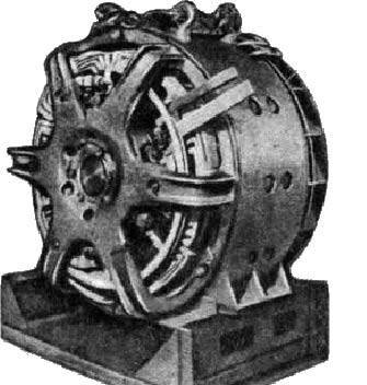
The generator of electromechanical transmission tank EKV
To reduce the size of the motor, increased the frequency of rotation of its armature to 5000 r / min. Traction motors could operate in two modes: long-term, which roughly corresponded to the second and third gears of the mechanical transmission, and short-term, which corresponded to the maximum torque or maximum speed. The main mode of operation of electric motors was long, which corresponded to the same mode of operation of the generator (with the simultaneous operation of both electric motors). The rotational speed of the armature in the continuous mode was 2400 revolutions per minute. In the circuit, the amperage reached 370 amperes. The speed of a heavy tank is 17,5 km / h. On the motor shaft, the maximum torque at 40 rpm was 520 kgm. The current in the circuit reached 2 thousand amperes. Centrifugal fans were used to cool the motors. The weight of each traction motor and fan was 820 kg. Mechanical transmission part experimental heavy tank ECV consisted of two combined DIP coaxial with the final drive belt floating brakes. Brake pads from Ferodo used for emergency braking of the tank, as well as its retention on the descents and ascents during stops. The gear ratio of the 235-kilogram airborne gearbox was 21. Motion control system - remote-contactor. The control controller and the relay system were used to switch the traction motors in the rectilinear motion, turning or braking. Each motor was controlled by a separate controller knob by a driver mechanic. The controller had ten contactors. Four contactors ensured reversal of the excitation series winding when switching to the reverse or braking forward.
Two contactors were used to switch the motor from the serial connection to the parallel one. Three contactors connected brake resistors to the engine during braking, and also closed the individual stages of the resistors. One contactor was designed to reduce motor excitation during deceleration. The coils of the contactors at different positions of the handle were switched on by the control controller. When both control handles were transferred to the zero position, both traction motors were disconnected from the generator. To start the movement of the tank forward, it was necessary to start the diesel and move both handles forward or to the third position, if the engines are connected in series (this position was used when implementing large tank tractive forces), or immediately to the end to the sixth position, if the engines were connected in parallel. When moving forward, the sixth position was normal. Mechanic-driver after installing the handles pressed the fuel pedal. In the future, the operator was not required to perform any other operations while driving in a straight line, the control system adapted to the driving conditions automatically, changing the speed depending on the change in the resistance to movement with the diesel operating mode unchanged. To rotate the machine, it was necessary to move the corresponding handle of the controller towards you. At the same time, the right or left traction motor was switched off. When finding the position on the first rear arm to the traction motor controller lagging side connected rheostat, provided the electric motor braking. In the event of a sharp turn or insufficient braking torque, the handle moved further back. The braking resistance at the second rear position decreased, causing the braking torque to increase. Both electric motors at the third rear position were connected in series with the braking resistance stage switched on, while the braking torque and current increased again. The brake resistor stage at the fourth rear position was short-circuited, which made the torque and current even higher on both motors. Motor lagging side when installing the handle controller to the last position of the rear fifth rotated back, providing thereby rotation of the tank around the axis of the ECV. When installed on the third or fourth position back lagging motor control handle while turning in the recovery of power from behind by a motor runs. If the driver during the movement of the tank released the fuel pedal, but both control knobs were in the second or first rear position, rheostats were connected to the traction motors, slowing the tank down. In the fourth or third rear position, engines were braked with the help of both diesel and rheostats.
The farther back the handles of the controller were advanced, the more intense the braking took place. When installed on the fifth rear position of both arms of the controller, the tank was moving backwards. At the same time, during the movement of an ECV tank in reverse, braking and turning were carried out in a similar way as during moving forward, only one lever was moved forward (for turning) or both (for braking). Without contact control, it would be impossible to place an electromechanical transmission in a KV-1 production tank. The right and left brakes of the onboard gearboxes were controlled by pedals independently of each other. For parking on descents and ascents, the drives of both brakes were blocked using a common lever lock. The undercarriage of the tank from the undercarriage of the KV-1 tank was not fundamentally different.
The electrical equipment of the tank was made using a single-wire circuit, with an on-board voltage network of 24 B. Four 12-volt 6STE-144 rechargeable batteries connected in series-parallel were installed in the ECV tank. The capacity of all batteries was 288 A / h. The batteries were charged from two GT-4563A generators (power of each 1 kW) installed on a diesel engine.
The radio station 71-TK-3 was installed in the forward part of the housing for external communication. Internal communication was carried out by means of TPU-4 tank intercoms. The large mass of electromechanical transmission units led to the fact that the combat weight of the ECV tank increased to 52 tons. The design of relay and contactor control systems was unreliable and very cumbersome. In the event that at least one contactor or relay failed, the tank stopped or lost control.
The main armament of the experimental heavy tank EKV was 76,2-mm ZIS-5 gun. The gun was installed in the axle tower and was completely balanced. The tower itself with the instrument was also balanced: the center of mass of the tower was located on the geometric axis of rotation. The vertical angle of the ZIS-5 gun ranged from −5 to + 25 degrees. The shot was made by means of electric trigger or manual mechanical descent.
Ammunition guns were 114 shots. The combat unit was located in the fighting compartment along both sides and in the tank turret.
On the EKV tank, as on the KV-1C, three DT machine guns of the 7,62 mm caliber were installed: one coaxial with the gun, as well as the stern and coursework in ball installations. The total ammunition of machine guns DT was 3000 cartridges. These machine guns were installed in such a way that when the need arose they were removed from the installations and used outside the tank. Probably, for the self-defense of the crew, the use of F-1 hand grenades was envisaged.
Technical characteristics of the tank EKV:
Combat weight - 52 tons.
Crew - 5 man.
Armor - counterbalance.
Engine power - 600 HP (441 kW).
Maximum speed - 36,7 km / h.
Armament:
The gun - caliber 76,2 mm.
Machine guns - 3 caliber 7,62 mm.
Based on materials:
http://ww2history.ru/
http://war1945.ru/
http://lib.znate.ru/
The use of electromechanical transmission on the tank made it possible to: reduce fuel consumption; improve traction characteristics; improve tank agility due to continuous regulation of the speed difference between the tracks, as well as improved braking performance due to electrodynamic braking.
Those. The design of the EKV tank was carried out in September of 1941 of the year, and the Dynamo plant began to manufacture electrical transmission units. Due to the redeployment of the academy and the evacuation of the factories, work on the creation of tank transmission units was delayed, and by January 1943, only 60% had been completed for the total amount of work. In February, 1943, the completion of the work was transferred to plant number 627 in Moscow.
In November-December, the 1944 of the year tested the prototype tank EKV at a research test site. Due to structural deficiencies, the EKV tank was not adopted by the Red Army, however, the experience gained during its development was later used in the design of electromechanical transmissions of the EC-6 and EC-7 heavy tanks.
The serial tank KV-1 of model 1941 of the year was used as a base for the manufacture of an ECV tank. The main differences from the base model consisted in the installation of an electromechanical transmission (on the KV-1 there was a mechanical one), as well as a turret with weapons (the same design was used on the KV-1С tank). The overall layout of the car had a classic scheme.
The driver’s seat as well as the radio operator were located in the control compartment. Also in the control department, in addition to the tank motion control drives, control devices, batteries, a DT machine gun, air tanks, a radio station, part of the spare parts kit and ammunition were placed. In the middle of the frontal armor plate of the hull there was a viewing hatch of the driver, which was closed with an armored lid with a viewing slot with triplex. A mirror-viewing device was installed in the hull roof to the right of the driver. In the frontal list in front of the gunner-radio operator there was a ball bearing for mounting a frontal machine gun. The entrance and exit of the crew members, which were located in the department of control, above the workplace of the radio operator in the roof of the vehicle's hull, was completed with a hatch that was closed with a folding armored cover on the inside loop. In the bottom of the case behind the driver's seat there was a spare hatch for exit.
The fighting compartment was located in the turret and the middle part of the tank hull. In the tower, which was installed on a ball bearing, mounted gun, machine guns, and also housed part of the ammunition. The control compartment housed: one after the other to the left of the gun the gunner of the gun and the tank commander, the loader - to the right of the gun. The seats of the commander, loader and gunner were attached to the tower. They rotated with her. On the roof of the tower above the commander's workplace, a fixed commander's cupola was installed, having five periscope viewing instruments located along its perimeter. In the roof of the tower, in the forward loader and on the stern of the tank, two mirror viewing instruments were mounted. In the roof of the tower to the right of the commander's turret there was an access hatch, which was closed with an armored lid on the hinge. The fuel and oil tanks were installed along the sides of the fighting compartment, on the bottom there was a rotating contact device and the main part of the ammunition.
Behind the fighting compartment was located the engine compartment. The branches were separated by a partition. The engine was installed on the sub-frame in the engine compartment along the longitudinal axis of the machine, alongside the oil and water radiators and two combined air purifiers.
In the stern of the tank was the transmission compartment, which was separated from the engine compartment. It housed the units of electric transmission and control equipment.
Bronezashita tank - protivosnaryadnaya, differentiated. The hull design of an EVA tank did not differ from the hull design of the KV-1 1941 model of the year. The exception was the roof over the transmission compartment, the manhole covers changes in which were made in connection with the installation of electrical transmission units and assemblies, as well as side plates in connection with the installation of new side gearboxes. In addition, the design of protective armor caps of engine exhaust manifolds was changed. Armor caps had a more elongated shape in comparison with similar parts of the KV-1 tank model 1941 of the year. The design of the tower is fully repeated the design of the tower KV-1С. On the tower there were no handrails for tank assault. A tetrachloric hand-held fire extinguisher was used to extinguish the fire.
Placement of electromechanical transmission units in an EKV tank
The structure of the electromechanical transmission included a DK-502B starter-generator permanently connected to the B-2K diesel engine by means of clutches, two DK-301B traction electric motors, two onboard gearboxes and control equipment.
The DC starter-generator DC-502B (weight kg 1240) was placed along the longitudinal axis of the tank housing EKV. The constancy of the generator power was achieved by selecting the generator excitation windings. It had an excitation winding 3: shunt, which was connected to the terminals of the generator; independent, which received electricity from the battery and worked in concert with the shunt winding; serial (anti-compounding), which received electricity from the generator and operated against independent and shunt windings. The winding data and characteristics of the generator were selected in such a way that the voltage decreases with increasing current and increases with decreasing current. Generator power with a decrease in engine speed decreased much faster compared to the power of a diesel engine. Thanks to this, the generator was automatically regulated to a constant power regardless of the speed and thrust force. This made it possible to use the full power of the diesel engine during its operation in various modes of movement - from the maximum thrust force to the maximum speed. A stable operation of the diesel engine was also ensured, since at any decrease in the rotational speed the diesel engine automatically unloaded and did not stop. The generator was made six-pole, had a loop winding of the armature and equalizing connections, located under the winding from the side of the collector. It provided short-term and long-term operation of the traction motors. In the main (long) mode, the generator power was 290 kW at 1700 rpm. In this case, the voltage was 392 B. In the short-term mode, the rotational speed of the armature of the generator increased to 1950 rpm, at this the power was 330 kW, and the voltage was 485 B. The generator was ventilated with a special centrifugal fan, which was integrated with the diesel engine cooling fan . Bearing support for the armature of the generator - only one. The second support of the armature of the generator was the coupling that connected the anchor of the generator and the crankshaft of the diesel. The DC DC-301B electric motors were installed across the housing and connected in parallel to the generator terminals using contactors depending on the position of the controller handle. The six-pole electric motors had an independent and series excitation winding. The independent winding of the excitation voltage was applied from the batteries. This electric winding winding provided a steady excitation of engines.
The generator of electromechanical transmission tank EKV
To reduce the size of the motor, increased the frequency of rotation of its armature to 5000 r / min. Traction motors could operate in two modes: long-term, which roughly corresponded to the second and third gears of the mechanical transmission, and short-term, which corresponded to the maximum torque or maximum speed. The main mode of operation of electric motors was long, which corresponded to the same mode of operation of the generator (with the simultaneous operation of both electric motors). The rotational speed of the armature in the continuous mode was 2400 revolutions per minute. In the circuit, the amperage reached 370 amperes. The speed of a heavy tank is 17,5 km / h. On the motor shaft, the maximum torque at 40 rpm was 520 kgm. The current in the circuit reached 2 thousand amperes. Centrifugal fans were used to cool the motors. The weight of each traction motor and fan was 820 kg. Mechanical transmission part experimental heavy tank ECV consisted of two combined DIP coaxial with the final drive belt floating brakes. Brake pads from Ferodo used for emergency braking of the tank, as well as its retention on the descents and ascents during stops. The gear ratio of the 235-kilogram airborne gearbox was 21. Motion control system - remote-contactor. The control controller and the relay system were used to switch the traction motors in the rectilinear motion, turning or braking. Each motor was controlled by a separate controller knob by a driver mechanic. The controller had ten contactors. Four contactors ensured reversal of the excitation series winding when switching to the reverse or braking forward.
Two contactors were used to switch the motor from the serial connection to the parallel one. Three contactors connected brake resistors to the engine during braking, and also closed the individual stages of the resistors. One contactor was designed to reduce motor excitation during deceleration. The coils of the contactors at different positions of the handle were switched on by the control controller. When both control handles were transferred to the zero position, both traction motors were disconnected from the generator. To start the movement of the tank forward, it was necessary to start the diesel and move both handles forward or to the third position, if the engines are connected in series (this position was used when implementing large tank tractive forces), or immediately to the end to the sixth position, if the engines were connected in parallel. When moving forward, the sixth position was normal. Mechanic-driver after installing the handles pressed the fuel pedal. In the future, the operator was not required to perform any other operations while driving in a straight line, the control system adapted to the driving conditions automatically, changing the speed depending on the change in the resistance to movement with the diesel operating mode unchanged. To rotate the machine, it was necessary to move the corresponding handle of the controller towards you. At the same time, the right or left traction motor was switched off. When finding the position on the first rear arm to the traction motor controller lagging side connected rheostat, provided the electric motor braking. In the event of a sharp turn or insufficient braking torque, the handle moved further back. The braking resistance at the second rear position decreased, causing the braking torque to increase. Both electric motors at the third rear position were connected in series with the braking resistance stage switched on, while the braking torque and current increased again. The brake resistor stage at the fourth rear position was short-circuited, which made the torque and current even higher on both motors. Motor lagging side when installing the handle controller to the last position of the rear fifth rotated back, providing thereby rotation of the tank around the axis of the ECV. When installed on the third or fourth position back lagging motor control handle while turning in the recovery of power from behind by a motor runs. If the driver during the movement of the tank released the fuel pedal, but both control knobs were in the second or first rear position, rheostats were connected to the traction motors, slowing the tank down. In the fourth or third rear position, engines were braked with the help of both diesel and rheostats.
The farther back the handles of the controller were advanced, the more intense the braking took place. When installed on the fifth rear position of both arms of the controller, the tank was moving backwards. At the same time, during the movement of an ECV tank in reverse, braking and turning were carried out in a similar way as during moving forward, only one lever was moved forward (for turning) or both (for braking). Without contact control, it would be impossible to place an electromechanical transmission in a KV-1 production tank. The right and left brakes of the onboard gearboxes were controlled by pedals independently of each other. For parking on descents and ascents, the drives of both brakes were blocked using a common lever lock. The undercarriage of the tank from the undercarriage of the KV-1 tank was not fundamentally different.
The electrical equipment of the tank was made using a single-wire circuit, with an on-board voltage network of 24 B. Four 12-volt 6STE-144 rechargeable batteries connected in series-parallel were installed in the ECV tank. The capacity of all batteries was 288 A / h. The batteries were charged from two GT-4563A generators (power of each 1 kW) installed on a diesel engine.
The radio station 71-TK-3 was installed in the forward part of the housing for external communication. Internal communication was carried out by means of TPU-4 tank intercoms. The large mass of electromechanical transmission units led to the fact that the combat weight of the ECV tank increased to 52 tons. The design of relay and contactor control systems was unreliable and very cumbersome. In the event that at least one contactor or relay failed, the tank stopped or lost control.
The main armament of the experimental heavy tank EKV was 76,2-mm ZIS-5 gun. The gun was installed in the axle tower and was completely balanced. The tower itself with the instrument was also balanced: the center of mass of the tower was located on the geometric axis of rotation. The vertical angle of the ZIS-5 gun ranged from −5 to + 25 degrees. The shot was made by means of electric trigger or manual mechanical descent.
Ammunition guns were 114 shots. The combat unit was located in the fighting compartment along both sides and in the tank turret.
On the EKV tank, as on the KV-1C, three DT machine guns of the 7,62 mm caliber were installed: one coaxial with the gun, as well as the stern and coursework in ball installations. The total ammunition of machine guns DT was 3000 cartridges. These machine guns were installed in such a way that when the need arose they were removed from the installations and used outside the tank. Probably, for the self-defense of the crew, the use of F-1 hand grenades was envisaged.
Technical characteristics of the tank EKV:
Combat weight - 52 tons.
Crew - 5 man.
Armor - counterbalance.
Engine power - 600 HP (441 kW).
Maximum speed - 36,7 km / h.
Armament:
The gun - caliber 76,2 mm.
Machine guns - 3 caliber 7,62 mm.
Based on materials:
http://ww2history.ru/
http://war1945.ru/
http://lib.znate.ru/
Information