The layout of the main battle tanks
Tank as an engineering structure is a complex of weapons, armor protection, bearing bases, power plant and chassis. The tank must be able to move both off-road (specific pressure on the ground, not exceeding the pressure of a person’s foot) and along the existing road network with artificial structures (weight with full load, not exceeding the carrying capacity of the bridge spans).
To the chassis tank general requirements are imposed on the caterpillar mover, primarily ensuring uniform loading of the track rollers. Ignoring these requirements leads to the following negative consequences:
- decrease in passability due to uneven specific pressure on the ground;
- increased vertical oscillations of the body when driving on rough terrain,
- reduce the speed of movement;
- reduce the accuracy of firing of the gun because of the lower efficiency of its stabilizer;
- increase crew fatigue;
- increased wear of the elastic elements of the suspension of support rollers and hydraulic shock absorbers.
Therefore, the layout of the tank must meet the requirement of the weight balance of its components relative to the center of the bearing surface of the tracks. The main massive elements of the tank structure include a gun turret, a gun, a gun ammunition, an engine, a transmission and fuel, as well as armor and dynamic protection. A crew that has an order of magnitude less weight, but occupies a large internal volume, also has a direct impact on the weight balance. The mutual arrangement of these elements and determines the effectiveness of the layout of the combat vehicle.
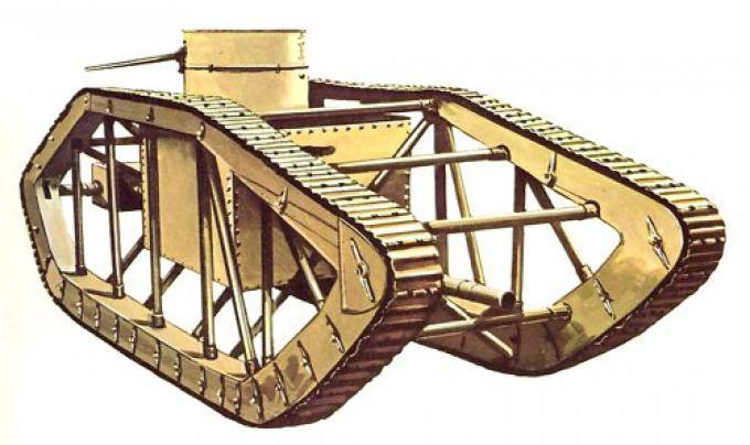
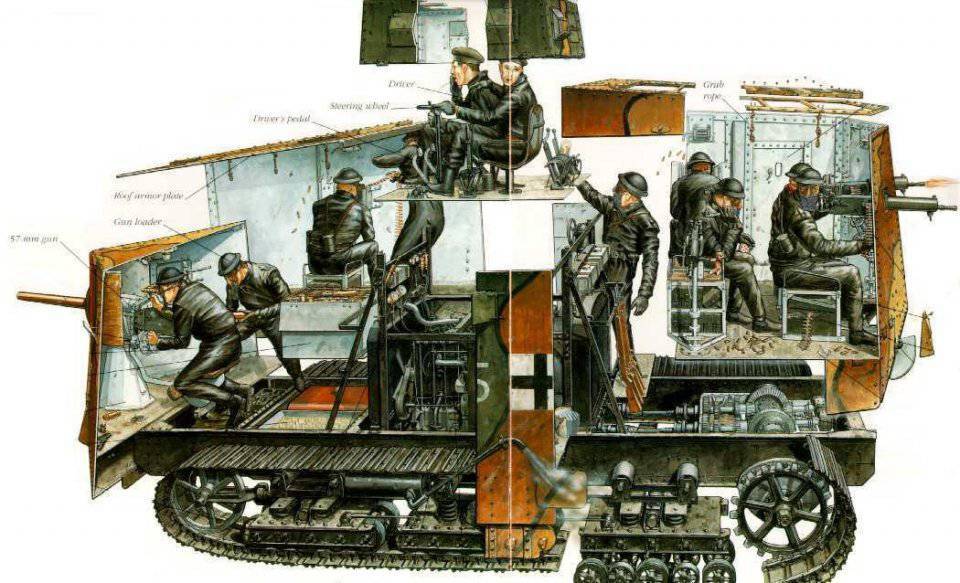
The first types of tanks, developed in Great Britain and Germany during the First World War, had the simplest layout - a general casemate of a corps with armament placed in the front (on the sides and / or in the frontal part), and the engine with the transmission, located in the rear. Ammunition and fuel were located in the center of the hull. The numerous crew and armor protection were evenly distributed throughout the hull. The gun turret as such was absent, casemate half-towers, symmetrically located along the hull sides, were used instead. Tracked propulsion had a chassis with a small course of track rollers, as can be seen from the example of the German tank AV7.
The experience of combat use of tanks of the simplest layout revealed their design flaws:
- weak armor protection of the casemate case with a developed external surface;
- the presence of large dead zones of shelling from guns installed in the casemate half-towers;
- low speed of movement over rough terrain due to the slow travel of the suspension.
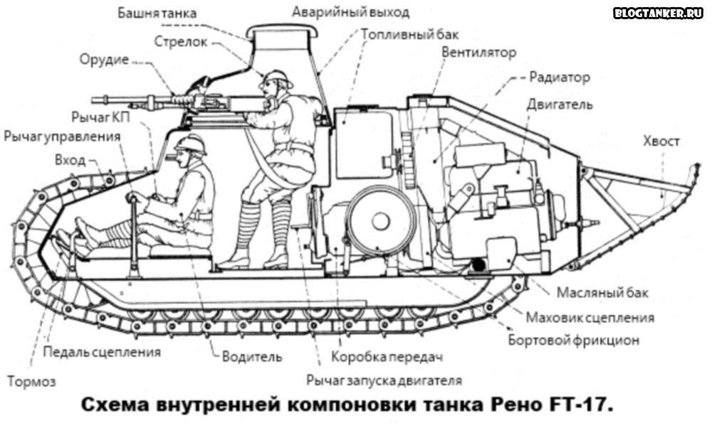
In this regard, at the end of the First World War in France, an optimal layout was developed for a new strike combat vehicle, which has since become a classic, replicated in hundreds of samples of experimental and production machines in many countries of the world. The hull of the Renault FT-17 had a very dense layout, which for the first time was divided into distinct functional areas — the nose section of the command, the central combat compartment and the aft engine compartment. A circular rotation tower with an 37-mm gun was installed in the center of the hull with a nose shift. A mechanic-driver was housed in the department of control, a tank commander and ammunition assembly in the fighting compartment, an engine, transmission and fuel in the engine-transmission compartment.
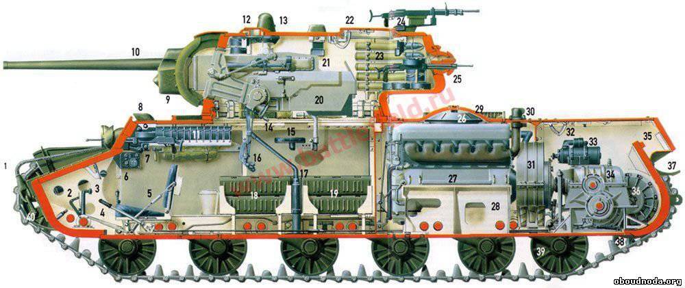
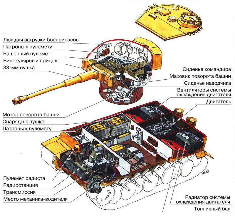
The development of this layout was the construction of the Soviet tank KV-1 of the beginning of World War II, whose tower had a developed feed niche, in which a significant part of the gun’s ammunition was located. At the end of the war, the last modification of the most massive Soviet tank T-34-85 received a similar tower.
Tanks in World War II in offensive operations were used in accordance with their unique combat specialization - as a means of breaking through fortified defenses, operating in direct fire contact with the enemy. In this case, the main threat of a tank defeat came from the frontal angle. This necessitated the differentiation of protection with an increase in the thickness of the armor of the front parts of the hull and turret and a corresponding decrease in the thickness of the armor of the side and stern parts. The center of gravity shifted forward relative to the center of the track bearing surface.
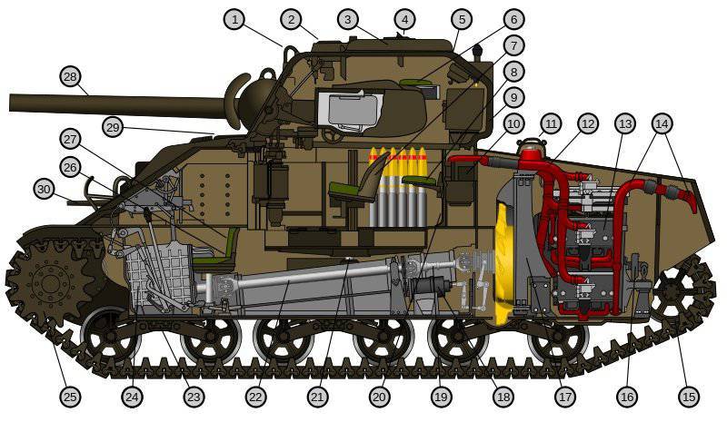
In order to restore optimal weight balancing of the tank, it was necessary to move its tower back. To this end, one more innovation was introduced into the classic layout: all German tanks and the American Sherman M4 tank had a spaced power plant — the gearbox and onboard gearboxes were located in the forward hull section of the hull. The engine was associated with the transmission of the drive shaft. This decision made it possible to shift back the heavy tower at the cost of moving forward a relatively light transmission.
The last version of the layout of the tank had two major drawbacks:
- the presence of a cardan shaft forced to increase the height, volume and surface area of the hull, reducing the degree of protection of the tank (the ratio of armored volume to the weight of armor);
- the front-mounted gearboxes of the tracked propulsion unit placed on the frontal surface were extremely vulnerable not only to armor-piercing projectiles, but also fragments and a shock wave from explosions of high-explosive fragmentation projectiles, in contrast to the classical layout, where the hull shields forage side-mounted gearboxes from frontal shelling.
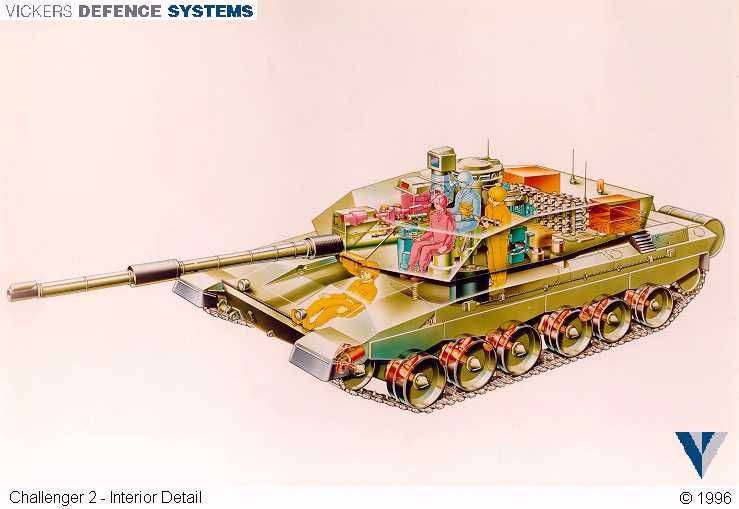
The solution to the problem was found at the end of the war by Soviet developers in the design of the T-44 tank. Without changing the classical layout, they reduced the length of the aft compartment due to the transverse arrangement of the engine and transmission, interconnected by a gear. The center of the bearing surface of the tracks shifted forward in the direction of displacement of the center of gravity of the tank. In the future, this engineering solution (reduction of the dimensions of the power plant) in combination with the previously implemented layout option (tower with developed aft niche) was repeated in the designs of the main battle tanks of the USA, Germany, France, Japan and South Korea, including those currently in service moment.
However, the retreat from the classic Renault FT-17 layout with the removal of ammunition into the feed niche led to a weakening of the tank's protection level due to the increase in zaronievy volume while creating excess space in the fighting compartment of the hull. The reason was that the hull height could not be reduced below the engine level in combination with its cooling system (approximately 1 meter). The height of the turret is determined by the extreme lowering points of the barrel (up to touching the edge of the upper frontal part) and raising the breech of the gun (up to touching the ceiling of the tower) when the guns are vertical (approximately 0,8 meters). When placing the commander and gunner mainly in the tower in the turret space is formed, a volume sufficient to store the entire ammunition.
The only problem is how to ensure the lifting of shots from the under-the-wall space and dismounting them into a gun. In 1964, this problem was solved in the Soviet T-64 tank by installing an automatic loader under the rotating floor of the crew compartment. All subsequent Soviet, Russian, Ukrainian and Chinese tanks are currently using this layout.
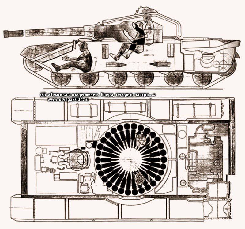
In another way, the American developers of the experienced T1958 tank tried to go in 92. Its original layout was based on the transfer of the engine compartment to the nose of the hull and combined with the control compartment, fenced off by an armored partition. The weight of the frontal armor, engine and transmission was balanced by the weight of the turret and ammunition. However, the combination of the length of the two sections of the hull forced to increase its height with the aim of the vertical layout of the equipment of the power plant. As a result, the tank increased the reserve volume and surface area of the hull while reducing the degree of protection. Despite the obvious lack of such a layout and the abandonment of its American developers, it was repeated in the Israeli serial tank Merkava and the Swiss experimental tank NKPz, which is most likely due to the lack of experience in designing tanks in these countries.

The increase in the effectiveness of modern armor-piercing and cumulative shells forced the developers to take another step in improving the design of tanks. As part of the development of the classic layout in the 1980-ies in the USSR and the United States, work was carried out on the creation of experimental tanks with uninhabited towers - Boxer / Hammer and ASM Block III, respectively. These works, brought to a high degree of readiness, were discontinued due to the lack of reliable electronic means of observation and aiming for the crew fully located in the hull at that time.
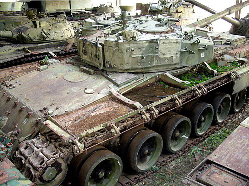
Work in this direction was resumed only in 2012 year as part of the project to create a new Russian tank "Armata". Based on modern achievements in the field of automatic systems for detecting and tracking targets, the project provides for a reduction of the tank crew to two people located in the control compartment. In addition to the uninhabited fighting compartment and the turret, a significant difference in the layout of the “Armata” from the layout of the Renault FT-17 is an increase in the length of the forward end of the hull to accommodate mounted modules of armor or dynamic protection. The increased length of the body has a positive effect on the displacement of the center of the track surface backwards. The size of the bow can be estimated from a photograph of an experienced tank "Object 187", which is used as a prototype of "Armata".
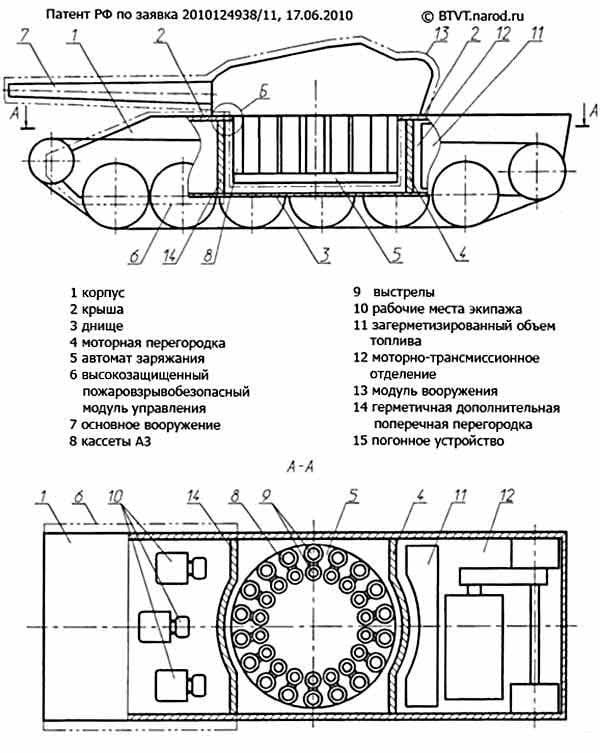
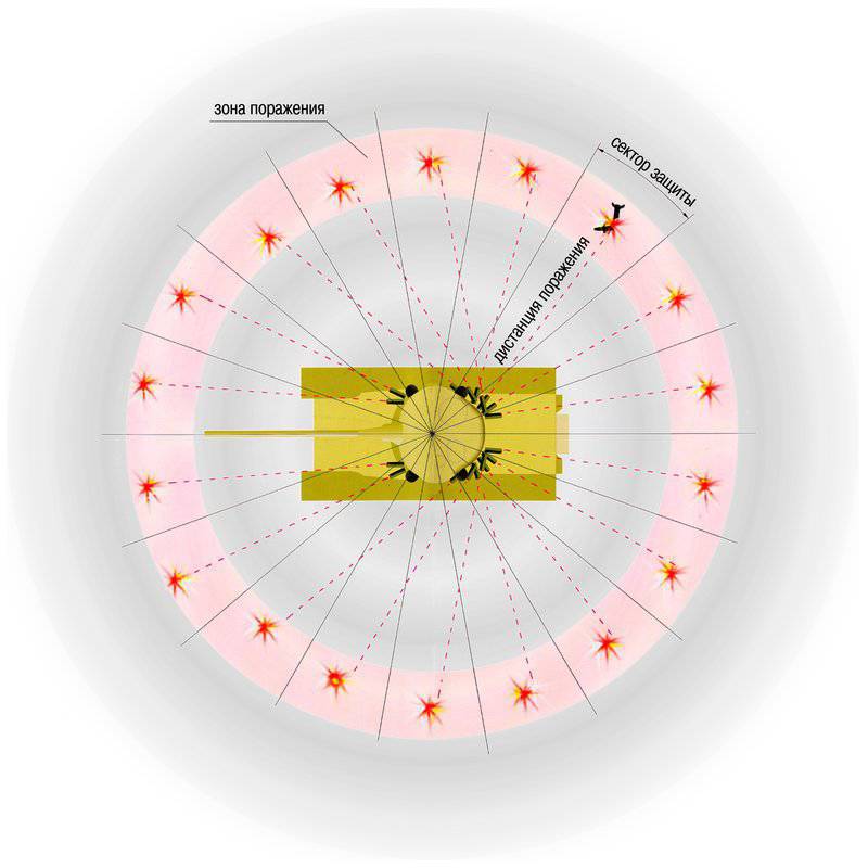
The projected development of the functionality of promising systems for active protection of tanks up to interception of high-speed kinetic projectiles makes it possible in the near future to reduce the requirements for passive armor protection of the tank, as well as its dynamic protection, currently being successfully used against low-speed rocket grenades and anti-tank missiles. Moreover, the number of launchers of damaging elements of active protection installed on each tank will ensure the simultaneous interception of two or more targets flying from the same or different directions. Based on this prediction, we can assume the rejection of dynamic protection, a reduction in the thickness of the reservation to the splinterproof and the transition to an all-round undifferentiated booking.
In addition, today there are ready-made solutions of hybrid power plants consisting of a heat engine (diesel or single-shaft GTE), an integrated electric generator, a lithium-ion high-capacity rechargeable battery and traction electric motors. It is possible to transfer the traction motors together with the onboard gearboxes to the forward part of the hull, evenly distributing the load along the length of the bearing surface (given the large volume occupied by the control compartment and the low weight of a two-person crew). In this case, the duplicated power cables connecting the generator with electric motors, unlike the cardan shaft of tanks of the Second World War, can be conducted along the hull sponsored sponsons without increasing its height.
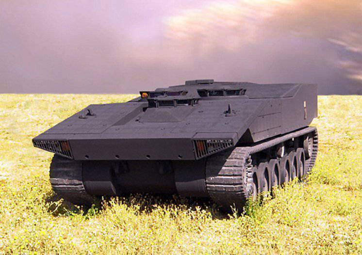
A tank with a similar layout was already developed in 2009, as part of the American FCS program, but did not go into the series due to the unavailability of the selected Quick Kill active defense system to intercept high-speed kinetic armor-piercing shells. However, given the progress in the development of this type of protection, it is now likely that this layout will be used in the US airmobile tank, the concept of which is developed by the US Army TRADOC command, and the Israeli main battle tank Rakiya, designed to replace the outdated Merkava tank. in the armored units of the Israel Defense Forces, beginning in 2020.
Information