Fuses of Russian naval artillery during the Russo-Japanese War. Tube arr. 1894
This material is an addition to my series of articles devoted to domestic naval guns and shells for them. I express my sincere gratitude to the respected Alexey Rytik (among other things, one of the authors of VO) for the assistance provided and the provision of some sources inaccessible to me.
Some theory
During the Russian-Japanese War, in service with the domestic fleet consisted of different types of fuses, also called tubes, including:
1) shock tubes for high-explosive projectiles - ensuring the detonation of the projectile after hitting an obstacle;
2) shock tubes for armor-piercing projectiles - ensuring the rupture of the projectile after passing through the armor;
3) remote tubes - providing detonation at a certain distance from the weapon that fired it;
4) double-action tubes - combining the qualities of spacer and shock tubes. That is, a projectile equipped with such a tube would explode at a given distance, but if even before it had covered this distance the projectile would hit the target, then, unlike a distance tube, the gap would still occur.
The article offered to the dear reader discusses the design and principle of operation of only two tubes, namely:
1) shock tube arr. 1894 (modified by Baranovsky);
2) a double-action shock tube designed by Captain A.F. Brink.
The reason for this selectivity is that it was these tubes that were equipped with domestic medium- and large-caliber steel armor-piercing and high-explosive projectiles, which became the main weapons Russian ships in naval battles of 1904–1905. I will not consider other naval tubes in this article, but for a better understanding of the design features I will present a brief description of the 11DM fuse, which was used for shells of coastal defense guns and occupies, so to speak, an intermediate position between the tube mod. 1894 and a Brink pipe.
The above tubes, including 11DM, were bottom, impact, inertial fuses. In this case, “bottom” refers to the location of the tubes that were screwed into the bottom of the projectile, “impact” refers to triggering as a result of contact with the target, and “inertial” refers to the force that ensures the impact of the striker on the primer.
I note that these pipes may be called slightly differently in the sources (for example, “pipe sample 1894”) but, of course, this does not change the essence.
Shock tube arr. 1894
Description of the design and operating principle of the sample tube. 1894, together with her drawing, I took from the textbook “Naval Artillery Course. Part I. Gunpowder, guns, shells and tubes” by I. A. Yatsyno (second edition, 1900), pp. 205–206. I note that the information given by I. A. Yatsyno is fully confirmed by the “Textbook on artillery for students of the classes of gunners and artillery non-commissioned officers of the artillery training detachment of the Baltic Fleet”, Section VI “Shells, projectile tubes, cartridge tubes for igniting charges and cartridges, flares and rockets", published by the printing house of the Naval Ministry in the Main Admiralty in 1909.
Unfortunately, the quality of the drawing leaves much to be desired, but the principle of operation can be explained on it.

The body was made of yellow copper and had the shape of a cylinder with one bottom. The head bushing (1) had a hole in the center for the passage of fire from the primer directly into the projectile body. This hole was covered with a thin brass gasket (2) to protect the inside of the tube from contamination. Of course, the gasket was thin enough that fire could easily overcome it when the primer was fired.
Below the head sleeve was an internal sleeve containing the capsule. The capsule was a cup of red copper (3), into which a shock composition (4) was pressed, which was a mixture of Berthollet salt, fulminate of mercury and antimonium.
Under the inner sleeve there was an extensor (5) - a cylinder with an internal wide through channel, which was not secured by anything and could move freely inside the tube, but rested on a safety spring (6), which will be discussed below.
And finally, the striker (7), equipped with a sharp sting (8). This striker could also move freely in the tube, but before the shot was fired, it was pressed to the bottom of the tube by an extensor and a safety spring.
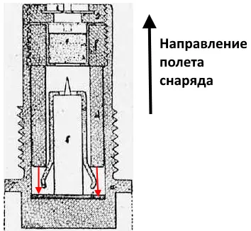
The principle of operation was very simple. During the firing of the projectile, the extensor, carried away by the force of inertia, shifted to the bottom of the tube, thereby compressing and straightening the legs of the safety spring.
After this, the drummer was free. But while the projectile was in flight, the striker, like the extensor, was pressed to the bottom of the tube by the same force of inertia directed in the direction opposite to the flight of the projectile. However, when a projectile hits a certain obstacle, it naturally expends energy to overcome it and slows down, losing speed.
At this moment, the striker, carried away by the force of inertia now in the opposite direction (in the direction of movement of the projectile), continued to move at a speed very close to the speed of the projectile before impact, covered the distance to the primer, struck and ignited it. The fire, having pierced the brass gasket, ignited the main charge of the projectile, resulting in an explosion.
It is interesting that V.I. Rdultovsky in his “Historical sketch of the development of tubes and fuses from the beginning of their use to the end of the World War 1914–1918.” contains information about the sample tube. 1883, which has an extremely similar device to the tube mod. 1894 with a minimum of differences.
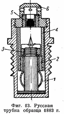
I can guess the following. Tube arr. 1883 was used in coastal artillery, which means it was created by the Military Department. It is likely that Baranovsky subsequently took its design and modified it for the needs of the fleet, after which it was listed in the Maritime Department as a tube mod. 1894. In this case, the naming of the sample tube becomes clear. 1894 by I. A. Yatsyno as “modified by Baranovsky.”
Tube arr. 1894 in the domestic fleet could be used exclusively in shells filled with smoky or smokeless powder. It was completely unsuitable for shells with pyroxylin filling, since the capsule it contained did not have sufficient power to detonate the pyroxylin charge in the projectile.
About instant fuses
The fundamental difference between an instantaneous impact fuse and an inertial one is their reduced operating time. For an instantaneous fuse it is 0,001 seconds, while for an inertial fuse it is about 0,005 seconds. approximate.
An instantaneous fuse can be a head fuse, which ensures the detonation of ammunition at the moment of contact with the target. As an example, I will give an illustration of their “Fundamentals of the device and design of ground artillery guns and ammunition” (Voenizdat, 1976).
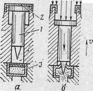
A – before the projectile hits the obstacle; b – when a projectile hits an obstacle; 1 – reaction striker; 2 – membrane; 3 – capsule
Due to the above and despite the fact that in the literature, for example, in the work of V. Polomoshnov “The Battle of July 28, 1904 (Battle of the Yellow Sea (Battle of Cape Shantung)", the tube model 1894 is often called an instantaneous tube (the author of this article also sinned with this), it is inertial, and its action time is longer than that of instantaneous tubes.
Features of inertial fuses using the example of a sample tube. 1894
The operating time of the return tube 1894 consisted of:
1) the period of movement of the striker from the moment of impact with the obstacle until the beginning of detonation of the capsule;
2) duration of detonation of the capsule;
3) the distance between the transfer of the thermal impulse and the distance from the primer to the gunpowder with which the projectile was loaded.
It is believed that inertial fuses have an action time of about 0,005 seconds, but in fact the specified time is not a constant.
Why?
The detonation time of the primer is fixed by its chemical composition and the amount of explosive. Unfortunately, I do not have drawings of the tube arr. 1894, but based on the drawings I have, it can be assumed that the thickness of the detonator capsule does not exceed 1 cm. Taking into account the fact that the detonation speed of fulminate mercury included in its composition is 5 m/s, complete detonation will occur in 400 ,0,00000185 s - that is, a meager time even by the standards of fuses.
As for the thermal impulse, assuming that it will need to travel 3 centimeters to go beyond the tube, and taking into account the propagation speed of the thermal impulse of 300 m/s, we obtain a time of 0,0001 seconds.
Accordingly, the time of detonation of the primer and transmission of the thermal impulse is negligible, and the vast majority of the duration of the fuse operation is occupied by the period of movement of the striker to the primer.
In turn, the time of movement of the striker was determined by two components:
1. The distance that the striker had to move. It consisted of the gap between the tip and the capsule and the so-called puncture depth - the distance that had to travel in the capsule to ensure the detonation of the latter.
In general, the sum of these lengths also tended to a constant. The distance between the firing pin and the primer at the sample tube. 1894 was approximately 9 mm. The penetration depth of the primer required for its detonation for modern ammunition is estimated at 1,2–1,5 mm; it was probably the same for the primer of the sample tube. 1894.
In total, the distance of movement of the striker can be determined as (on average) 14 mm.
2. The speed of movement of the striker relative to the projectile body. It depends on a number of external parameters, such as, for example, the deviation of the projectile’s flight path from the target plane at the moment it hits it, the speed of rotation of the projectile, etc.
There are also internal factors - the drummer of the tube arr. 1894, following to the detonator, will drag behind it a safety spring, the legs of which will come into contact with the extensor, and energy will be spent on this.
There is no need to consider all these factors in this article, and, frankly speaking, it is not possible - I am still not a physicist by training. Therefore, further on, as an example, I will consider a simple case that is understandable even to a non-specialist - a projectile hitting a flat target at an angle of 90 degrees to its surface (the deviation from the normal is zero). I ignore the friction force of the striker during movement as insignificant - you still need to understand that when removing the safety spring with an extension, the striker moved freely inside the tube.
Taking into account the above assumptions, the speed of the striker relative to the projectile body will be equal to the speed that the projectile will lose in the process of overcoming the obstacle - after hitting it, the projectile will fly slower, and the striker inside it will maintain the same speed that the projectile had before hitting the obstacle.
A very simple fact follows from this. The operating time of the return tube 1894 was determined primarily by the strength of the barrier that the projectile equipped with it collided with.
A few calculations
Let's try to simulate the operation of the sample tube. 1894 using the example of a 6-mm projectile hitting a 12-mm steel sheet at a speed corresponding to a distance of 15 artillery cables.
For this we use de Marre’s formula for uncemented armor below 75 mm, given, for example, in the “Course of Naval Tactics. Artillery and armor” by Professor L. G. Goncharov.
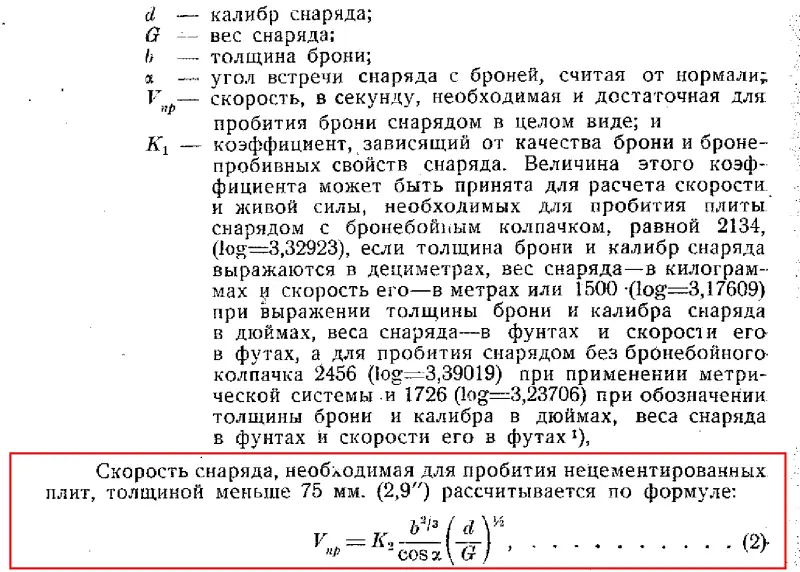
We accept:
– “K” for a 12 mm steel sheet equal to 1, which is slightly lower than the resistance value of homogeneous armor recommended by a respected professor;
– striker movement distance 14 mm.
We get that a 6-dm projectile weighing 41,5 kg, fired from a Kane cannon at a distance of 15 artillery cables, will have a speed on the sheet of 509,9 m/s, and after overcoming it - 508,4 m/s. The difference in speed will be 1,495 m/s. This in turn means that the striker, until the moment of contact of the projectile with the steel sheet, was moving at a projectile speed of 509,9 m/s and had a speed relative to the projectile of 0 m/s, and after overcoming the sheet, its speed relative to the projectile increased to 1,495 m/s. Accordingly, the average speed of the striker during the time of overcoming the obstacle was half of this value or 0,7476 m/s.
Let us assume that the projectile lost its speed when overcoming the steel sheet evenly from the moment it touched until the moment the bottom part of the projectile exited the sheet envelope. Then the projectile lost speed at a distance equal to its length plus the thickness of the obstacle; for a 6-inch projectile this would be approximately 0,5 m. The projectile covered this half-meter with an average speed of 509,15 m in approximately 0,00098 seconds.
Consequently, from the moment the projectile came into contact with the obstacle, the striker moved for the first 0,00098 seconds at an average speed of 0,7476 m/s, and then at a speed of 1,495 m/s.
From here it is easy to calculate that the striker will cover 14 mm in 0,0096 seconds. By this time the projectile will be at a distance of 4,51 m (the distance between the bottom of the projectile and the steel sheet). At this moment the capsule detonates. And after another 0,0001 seconds, during which the projectile will cover 5 cm, the thermal impulse will reach the gunpowder with which the projectile is equipped.
But there is a nuance here.
When a projectile is loaded with pyroxylin or another detonating substance, when it is “initiated,” the explosion occurs almost instantly, since the speed of detonation in blasting substances reaches 7 m/s.
However, in the case of gunpowder, everything is different - it does not detonate, but burns in the projectile, and the rate of its combustion depends on the pressure, and it, naturally, increases like an avalanche. Accordingly, it should be expected that some time will elapse between the ignition of the gunpowder in the projectile and the explosion of the projectile. But, again, it is small - if we assume that the rate of combustion of gunpowder in the chamber of the projectile is comparable to the speed of propagation of the thermal impulse, and taking into account the fact that the distance from the bottom tube to the end of the charging chamber is, depending on the caliber and design of the projectile, no more than 40–60 cm, the thermal impulse covers this distance in 0,0014–0,002 seconds, during which the projectile from the above example will cover no more than 0,7–1 m.
But, again, the destruction of the projectile will clearly begin before the thermal impulse reaches the end of the chamber, so it is incorrect to say that the explosion will occur 0,7–1 m after the ignition of the gunpowder with which the projectile is equipped. Here, rather, we will talk about the duration of the explosion, and 0,7–1 m will be the distance that the projectile, which is already collapsing during the explosion, will cover.
Taking into account the above, in the example described above, the explosion of a 6-dm projectile equipped with a sample tube. 1894, you should expect about 5–5,5 meters behind a 12 cm sheet.
In the naval manual's article “Projectile response. Differential part" provides an indication of experimental firing, during which shells equipped with a sample tube. 1894, when a 12-mm steel sheet was hit, it caused a gap 5–6 meters behind it. Unfortunately, the respected author did not provide a direct link to the document from which this information was taken. But what’s even sadder is that there is no data on the caliber of the projectiles, and this is very important, since the drop in speed for projectiles of different calibers and masses when hitting an obstacle of the same resistance will be different.
With the same speed of hitting the target, a heavier projectile will have more “manpower” than a light one. The more “manpower” he has, the less speed he loses when overcoming an obstacle. The smaller the loss of projectile speed when overcoming an obstacle, the slower the striker in the projectile moves relative to the projectile. The slower the striker moves, the later the explosion will occur and the greater the distance the projectile will cover before the explosion.
If the test was carried out with 152-mm shells, then we can say that my calculations are completely correct. But when the same 12-mm steel sheet is hit by a 12-mm projectile weighing 331,7 kg, with the same speed of 509,9 m/s (which corresponds to a range of 5 m), the explosion should occur somewhere around 280 –19,6 m behind the obstacle. This is due to the fact that at a speed of 20,6 m/s on a 509,9-mm steel sheet, a 12-dm projectile loses 6 m/s when overcoming it, and a 1,495-dm projectile loses only 12 m/s. Accordingly, the firing pin of a 0,374-inch projectile will hit the primer many times later than its counterpart on a six-inch one.
Conclusions
I made calculations for distances from 5 to 40 cables for the most powerful 12-dm projectile weighing 331,7 kg for Krupp cemented armor with “K” = 2, as well as for homogeneous armor. I took the time of the explosion to be the moment when the thermal impulse reached the gunpowder with which the projectile was loaded.
Taking into account all of the above and provided that I did not make critical mistakes in my thinking, the following is obtained. When firing a domestic high-explosive 12-inch projectile with a tube arr. 1894 from a standard Obukhov 12-dm gun with a barrel length of 40 calibers:
1. When hitting a spar equivalent in durability to 12 mm steel (say, a metal cable), the projectile should have exploded at 15 m (hit at a distance of 40 cables) - 41 m (5 cables) behind the obstacle.
2. When hitting pipes and superstructures, everything depended on the width of the superstructure, the number and thickness of the bulkheads in it. Overcoming an obstacle equivalent in durability to 36 mm steel should have caused the projectile to explode 4 m (40 cables) - 9 m (5 cables) behind the obstacle. We can, perhaps, say that the explosion must have occurred either inside the superstructure, or behind it, but above the deck of the ship.
3. When hitting uncemented armor 75 mm thick, a 12-inch projectile should have produced a gap of 40 m at 2,5 cables, and approximately 5 meters behind the obstacle at 4 cables.
4. In absolutely all cases of contact with cemented armor, even with a minimum slab thickness of 127 mm (at the end of the XNUMXth – very beginning of the XNUMXth centuries, they were not yet able to cement slabs of smaller thickness) and at all distances, the projectile should have burst in the process of overcoming the armor.
Of course, all of the above is not dogma. We must never forget that fuses, like the projectiles themselves, perform their functions under conditions of extreme acceleration and deceleration and can act without permission. In battle, a twelve-inch projectile equipped with a tube mod. 1894 could easily explode immediately upon contact with the skin or, conversely, rupture after breaking through the armor plate.
Let me remind you that even German fuses from the era of the First World War did not always work as intended, causing premature explosions, which I described in the article “About damage to the battlecruiser Lion in Jutland. Should the Germans have fired armor-piercing weapons?. Of course, the opposite situation is possible, when for some reason the sample tube. 1894 worked later than expected.
The conclusions that I indicated above are, let’s say, some average values to which Russian 331,7 kg high-explosive steel shells equipped with a tube mod. 1894.
Well, we’ll talk about tubes for shells containing pyroxylin in the next article.
To be continued ...
Information