Development of the destroyer theme for the Russian Navy
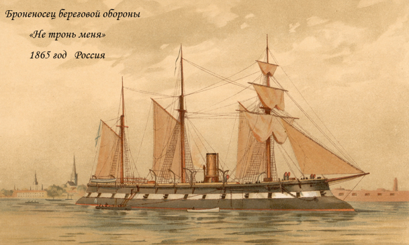
And hello again, not even a year has passed since the beloved author of the nuclear-powered armored destroyer ABM/PLO is ready to share new creative ideas for the development of the project, and Zamvolt was launched ten years ago.
Chassis
The main dimensions, length, width, displacement remained the same, because we are building a series of destroyers, but the proposed development is aimed at adapting the project to operating conditions in the north and east of our country. The region of our country from Murmansk to Vladivostok, even along the coast of two oceans, even along a straight line on the map, joined the Russian civilization conditionally no more than three centuries ago. And this very civilization, and the so-called progress, was carried here by the fleet, first on sailing ships, then on steamships.
And in our time the fleet it is necessary to protect and defend this difficult region. Just as the differences between cruise ships for travel in the tropics and tours to the Arctic and Antarctic are little noticeable, the differences between a simple destroyer and a sistership for the northeast and the Arctic will also be little visible.
The armoring scheme of the ship with a continuous armored deck and an armored citadel located below the waterline was unanimously criticized.
Two historical example.
In 1941, the German battleship Bismarck, in a battle with an English battleship and a battle cruiser, was forced to interrupt a joint raid with a heavy cruiser and return to the nearest German-controlled harbor at the shortest possible speed due to damage to the bow fuel tanks (a trim on the bow and loss of fuel). The diving shell damaged the unarmored compartments of the hull.
In 1982, the British destroyer Sheffield was lost when it hit the freeboard. aviation The Exocet anti-ship missile system, which did not even explode, but caused a fire in the engine room. I have no doubt that the waterproof compartments of the ship were battened down for combat, and only the presence of an armored deck, like our ship, could have prevented the disaster.
Thousands of tons of armor or its complete absence, probably, the truth is somewhere in the middle, in a reasonable compromise of all available means of protecting the ship. Opinions have been expressed about the negative impact of armor protection on the availability and cost of repair and maintenance of internal units and systems, as well as on the deterioration of ship stability.
Let me disagree and challenge.
A horizontal armored deck at the level of the lower waterline in the bow of the ship will serve as a natural platform for placing vertical launch installations for the missile arsenal and will be a guarantee against a repetition of the ridiculous Sheffield tragedy, and will also strengthen the ship’s hull for sailing in icy waters in the most vulnerable place from the effects of ice fields. Its logical and natural continuation to the stern will reliably prevent the nuclear reactor and the ship’s energy from various incidents from the aircraft hangar and take-off pad located on the upper deck.
In addition, the placement of the armored deck below the waterline, and below it the armored citadel of two vertical transverse armored beams and two longitudinal armored bulkheads, which have become the natural boundary of the onboard anti-torpedo protection, will only have a positive effect on the metacentric height and center of mass of the ship. Therefore, the presence of such armor protection will improve the stability of the ship in comparison with non-armored analogues.
As for the accessibility and ease of repair and maintenance of internal compartments, with a competent and careful approach to designing a ship’s hull, the proposed armor will cause no more problems than the necessary division of the hull into compartments (from 14 to 20) with waterproof bulkheads and decks.
So, there are three invisible but fundamental differences between the ship’s hull for the northeast and the previous series: a change in the inclination of all surfaces of the hull and superstructure from 10 degrees to 9 degrees; increasing the boundary line for changing the slope of the sides from external to internal from one and a half meters to 2 meters from the waterline; construction of the ship's hull in accordance with the requirements of the Arc4 standard for shipping in the Arctic.
“Arc4 (LU4) - Independent navigation in rarefied 1-year Arctic ice with a thickness of up to 0,6 m in winter-spring navigation and up to 0,8 m in summer-autumn navigation. Sailing in the channel behind the icebreaker in 1-year Arctic ice up to 0,7 m thick in winter-spring and up to 1,0 m in summer-autumn navigation.”
A long, narrow and tall alternative ship's stem is proposed for two reasons.
Firstly, according to unconfirmed research by European shipbuilders, the reverse tilt of the stem reduces the wave resistance to the movement of the ship, which, together with a large fairing and protection of the bow hydroacoustic complex, should help increase speed and energy efficiency, as well as reduce the ship’s slamming in stormy weather.
Secondly, such a configuration of the bow of the ship should help it perform the functions of an ice cutter, yes, just an ice cutter, and not an icebreaker. An ice field or floe is not pressed through or broken by the icebreaker's hull from top to bottom under the influence of gravity, but is “cut” from under the water by a sharp, narrow stem. The icebreaker, as it were, crushes the broken ice under itself and under the ice field, while the ice cutter with an alternative stem cuts, pushes the fragments to the sides or even onto the surface of the ice field, thereby reducing the risk of damage to the bow propeller, propeller and rudders.
If you look at the drawing, you can understand that the ship’s bow gauge is 6 meters ahead of the waterline, and the steel upper part of the sonar fairing begins at a depth of two meters under water. A sharp, narrow stem immediately begins to form.
Actually, a durable sound-conducting fairing starts from a depth of 3,5 meters. The process of ice breaking itself begins at the point of contact of the stem on the waterline, when the fairing is already under the ice at a safe distance and depth. The thickness of the plating on the stem of modern heavy-class icebreakers reaches 40 millimeters. The ice cutter "Fedor Litke", aka "Earl Grey", aka "Canada", was 31 millimeters.
By the way, the idea of an ice-cutting destroyer arose after becoming familiar with the history of this ship. I recommend reading it. For our new destroyer with the option of an ice cutter for its own needs, the thickness of the plating in the bow and 30 millimeters is sufficient.
Dry calculations show that even if with this method of overcoming the ice field, an ice floe with an area of 25 square meters will be lifted from the water on the stem. meter and 0,5 meter thick, which did not break from impact or under its own weight, then for a ship it will be comparable to landing a standard helicopter on the stern. Twice the displacement and length of an ice-class destroyer compared to an ice cutter of the last century, as well as incomparable energy power, are the key to the success of the proposed project.
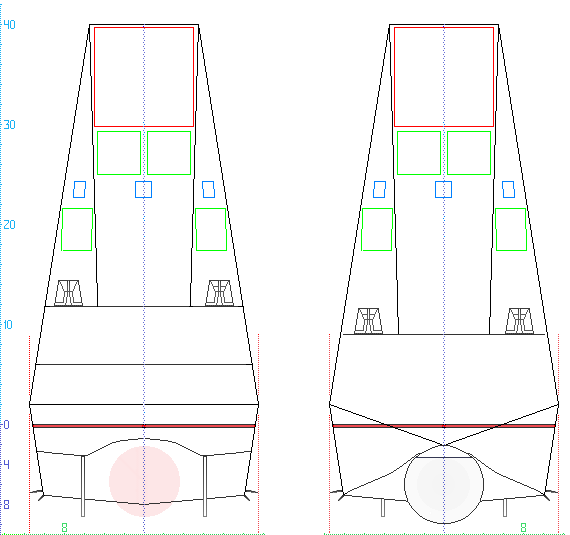
Thus, like all natural inhabitants of polar latitudes, our ship becomes more dense, stocky and squat (the height of the superstructure is reduced from 41,5 meters to exactly 40). Thanks to the above set of changes, the longitudinal sectional area of the superstructure from the aircraft hangar roof level was reduced by 80 square meters (16% compared to the prototype), but at the same time, unfortunately, the cross-sectional area of the superstructure at the same level increased by 24 square meters meters (by 6% compared to the prototype).
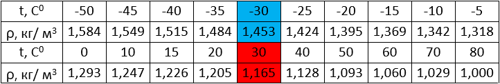
One way or another, all of the above changes will somewhat reduce wind loads on the surface structures of the ship’s hull. According to table number one, a wind with a speed of 25 m/sec will be much stronger in the Arctic than in the subtropics or on the Black Sea. Air density depends on temperature at normal atmospheric pressure.
Radars
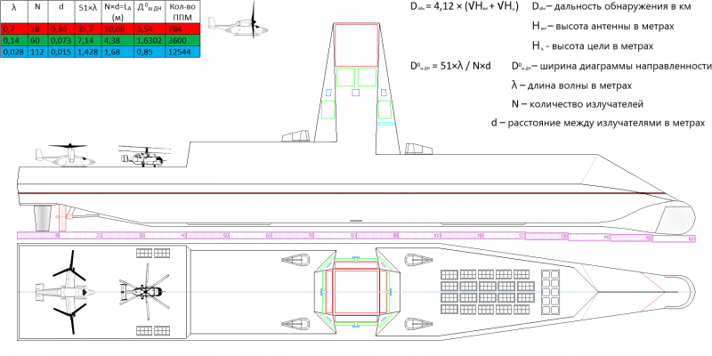
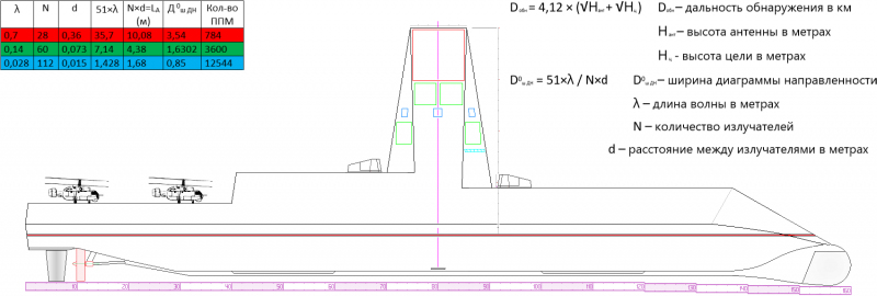
One may get the impression that the author, under pressure, is trying to somewhat sacrifice the basic principle inherent in the design of the missile defense/anti-submarine warfare destroyer: priority is given to reconnaissance and control equipment. As we remember from the previous article, five “red” AFARs of the decimeter range of a rectangular shape with sides of 24 and 32 transceiver modules, placed in the maximum possible optimal positions on the top of the ship’s superstructure, actually formed its unique appearance in the form of the maximum permissible high tower for 3D -RLK (three-band radar complex).
In the new configuration of the 3D-radar for the missile defense/anti-aircraft missile destroyer of the northeastern region, we will somewhat shift the emphasis from conducting effective long-range radar reconnaissance in the interests of regional formations of the armed forces towards the reliable provision of intelligence information and covering the actual naval formation of the area it leads or the protected area.
When the ship is in combat service in the NSR areas of the Arctic Ocean or the Chukotka and Kamchatka peninsulas in the northwestern part of the Pacific Ocean, it will still be able to detect ballistic missiles and warheads aimed at strategic targets within the country, but they will be inaccessible to its anti-missile missiles from -for heights and trajectories. And they are hardly applicable to the “bastions” of duty of our SSBNs. But here a mass launch of air- and sea-based strategic cruise missiles with the aim of a pre-emptive disarming strike is possible.
The above-mentioned reduction in the height of the ship’s superstructure and its longitudinal section logically entailed a change in the geometric dimensions of the “red” AFARs and the inclination of the planes of their placement. The decimeter antenna panels were converted from rectangular ones to square ones with a square side of 28 PPM and a geometric size of 10,08 meters. An increase in the number of PPMs in the antenna fabric by 16 units also slightly increased the energy potential of the APAA.
Due to the reduction in the inclination of the surfaces of the ship's superstructure to 9 degrees, the viewing area of the antennas on the side surfaces in the elevation plane was correspondingly reduced to 54 degrees, while the remaining 90 degrees in the azimuthal plane remained the same. Accordingly, the viewing angles of the horizontally located AFAR increased to ±36 degrees in the longitudinal and transverse planes from the normal. Changing the pulse repetition rate for radiation in accordance with the established values of the instrumental range scales of 500, 1 and 000 kilometers will allow for flexible and fruitful reconnaissance depending on the assigned tasks.
The “red” decimeter band 3D-RLK, by analogy with the 5N84A and 55Zh6 meter band RTV VKS radars, should confidently take on the tasks of long-range radar detection in standby mode. The only weakness of this part of the project may be insufficient time between failures (for comparison: for the mentioned radars it is 114 and 250 hours, respectively). The presence of such a radar on board our destroyer turns the American-Japanese missile defense destroyers with Aegis simply into blind-sighted nerds!
Indeed, for all four phased arrays, the height of the electrical center of the antenna is at the level of 35 meters from the surface of the water, this is ten meters higher than the placement of the locators of the S-300 complex on the 40V6M tower and is only slightly inferior to the 40V6MD product (39 meters).
Direct competitors to the sixth-generation American style icon AN/SPQ-6 Aegis will remain “green” radars of the short decimeter range (λ=14 cm). American aircraft carriers have not come close to the red line of the Arctic Circle or the 67th parallel for thirty years. Therefore, an air strike by carrier-based aircraft as part of an air wing entering from the Barents Sea at the bases of the Kola Peninsula is hardly possible. And the breakthrough of an aircraft carrier through the Bering Strait into the Chukchi Sea is absolutely incredible. In the event of a global conflict, one should not expect a significant concentration of strike aircraft at the northern airfields of Norway and Finland, as well as at the bases of Alaska and northern Canada.
Taking into account economic feasibility and the principle of reasonable sufficiency, the number of “green” range AFARs on the destroyer version for the northeast has been reduced from 16 to 12, which will allow the ship to fire all-round at up to 48 air targets at long range. If this fact is interpreted as a slight reduction in the ship’s combat capabilities, then we should also consider some newfound advantages.
Thus, 12 “green” radars have increased the energy potential of radiation due to an increase in the number of PPMs in the AFAR, there are now 60 of them in each vertical and horizontal row (in the previous version 58 × 58), which also entailed some slight narrowing of the radiation pattern antennas In the new version, the antennas are placed more rationally, from eight directions instead of four on the previous version.
Prerequisites for construction
The cost of building the nuclear icebreaker "Arktika" pr. 22220 is widely known, amounting to 37 billion rubles ($625 million). The prices for the three production ships of this project are already known; they are steadily increasing from 42 billion rubles ($709 million) for the second, 44 billion ($743 million) for the third and up to 51,8 billion rubles for the fourth. Although, according to the laws of economics, the prices of serial ships should decrease, so there is no point in arguing and breaking spears about the monetary equivalent of building the proposed destroyers.
Let's try to justify the possibility of their construction through comparisons and analogies.
So, the price of the third icebreaker, project 22220 Ural, according to various sources, is in the range of 44–48 billion rubles. The price for the Borei class strategic submarine missile carrier is also publicly available - 23,2 billion rubles. Both types of ships are currently being built in relatively large series, which means the construction technologies have been proven and are available under Western sanctions. Until 2028, the Baltic Shipyard shipbuilding enterprise will be busy building icebreakers. So what is next?
And then, in a dock measuring 350x36 meters, two hulls of nuclear-powered armored missile defense/anti-aircraft destroyers are laid down at once, to choose from two proposed options. The icebreaker weighs 26 tons; this amount of material is enough for two destroyer hulls with a displacement of 800 tons. If for an icebreaker it is necessary to produce three propellers with a diameter of 10 meters, then it will not be a problem to produce two propellers with a diameter of 000 meters for destroyers. The icebreaker has two reactors that convert the energy of nuclear fuel into steam energy, and then turbogenerators convert it into electricity, which in turn drives the propellers through electric motors.
By using a serial and reliable main power plant from the latest generation of SSBNs on the latest destroyers, we are practically guaranteed from suffering with gearboxes, gas turbine and diesel engines, we leave childhood illnesses behind and fundamentally solve the issue of ship autonomy when sailing in high latitudes.
Additional bonuses from such a solution will be the higher efficiency of the power plant of destroyers compared to the icebreaker version due to the smaller number of fuel energy conversions and the initially designed lower noise level of the power plant for the Borey and Yasen submarines, transferred to the surface ship.
In the future, the industry will fulfill orders both for the construction of submarine missile carriers and for the construction of nuclear icebreakers. Their renewal will be required no earlier than in 15–20 years, until new projects appear and the service life of existing samples is exhausted. It is logical to use the predictable pause to build equally necessary equipment of a different class using mass-produced units.
Thus, we have for destroyers a reliable nuclear power plant that has been mastered in production, a hydroacoustic complex that needs only minor adaptation for operation on a surface ship, and a full arsenal of mass-produced modern missile weapons; a non-critical percentage of novelty for a new product will only be presented the above-described three-band radar system and a completely new aviation armament component consisting of new generation anti-submarine helicopters, AWACS tiltrotors and airborne drones.
Many readers are not against the construction of universal destroyers for the Russian Navy, but at the subconscious level they object to nuclear energy for them. But there is no alternative for it, and even development is not expected. The recently existing model range of marine gas turbine engines from M75RU (7 hp), M000FRU (70 hp) and M14FR (000 hp) and the level of development of mechanical engineering in our country do not allow the creation of a power plant for a destroyer with a displacement of 90 tons.
The pinnacle of achievement so far is the power plant for frigates Project 22350, each of the two shafts of which is powered by a pair of a sustainer diesel engine (5 hp) and an M200FR afterburner turbine through a gearbox that is not capable of summing up their power (i.e., rows one of units). On the next series of frigates, Project 90, with increased UKSK ammunition and, as a consequence, increased displacement and length, it is planned to leave the power plant unchanged.
This means that the economic speed will become even lower than that of the frigates of the first series, and the newest ships of the first rank are doomed in advance to be outsiders among their foreign classmates in this parameter. The use of a more powerful diesel engine (6 hp) with the same gearbox and turbine in the second series could somewhat smooth out the lag, but not overcome it. The forecast for the power plant for the enlarged project 000M is more optimistic: it is planned to install a pair of M22350FRU and M70FR turbines on one unit.
The only question is whether it will be possible to create a gearbox for them that sums the power of both turbines. Otherwise, with an increase in economic speed, we will lose the maximum value of full speed in comparison with frigates of the first series, for which it is not outstanding anyway. Note that the displacement of ships of Project 22350M is planned to be up to 8 tons. This means that for a destroyer with a displacement of 500 tons, such a power plant, even in its best version with summing gearboxes, will be rather weak.
And even the creation of a unit with two M90FR turbines and a gearbox with a capacity of 55 hp that sums their power on one shaft. With. does not seem to be a prerequisite for national pride.
Thus, at the moment, there are not even clearly stated plans to create a power plant based on internal combustion engines for a ship with a displacement of 10 tons. On the other hand, submarines of the Yasen type (full capacity 000 tons) and Borey (full capacity 13 tons) with full speeds of 800 and 24 knots, respectively, are being built in series.
Maintenance and operation of nuclear power plants on surface ships will not be more expensive than similar activities for submarines. And if the leadership of the fleet and the country now makes, of course, a bold decision to build nuclear destroyers, then in the first half of the 30s we will be able to have in one of the fleets a full-fledged division of six ships for the price of a division of missile submarines.
Convertiplane AWACS
No matter how good the tri-band radar system located on the destroyer is for reconnaissance, issuing target designation and controlling the ship’s weapons, this excellent system also has drawbacks that limit the possibilities of using the carried weapons and can be used by the enemy for unexpected defeat.
First of all, these are the limitations imposed by the radio horizon both on the detection of dangerous targets at extremely low altitudes, and the limitations of confident, accurate target designation in real time for the ship's long-range missile weapons.
Quite paradoxically, even for a well-armed modern ship, the main threat comes from the surrounding airspace, but carriers can be not only flying objects, but also submarines and surface ships. Therefore, long-range radar detection, both for an individual ship and for a ship warrant, has long been the cornerstone of combat sustainability. Our powerful, beautiful and expensive destroyers are designed to be provided with this very AWACS by tiltrotors based on them.
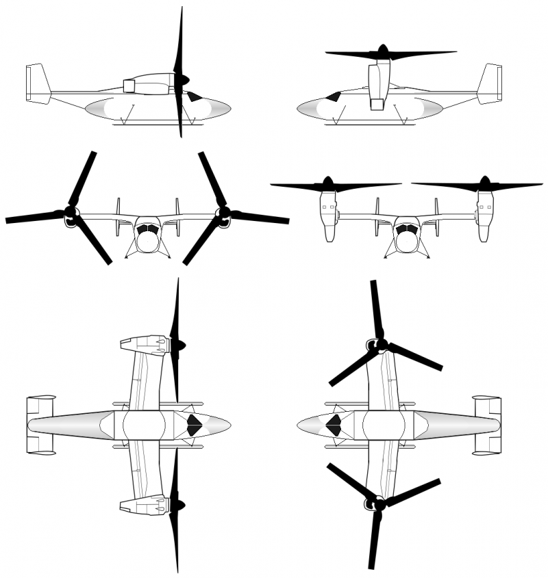
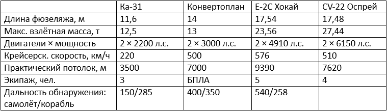
First, we need to dwell on the conceptual issues of the possibility of creating an unmanned (unmanned) tiltrotor AWACS. The Hawkeye AWACS has a crew of five people; the Osprey transport and landing tiltrotor has a crew of three to four people.
By creating an unmanned tiltrotor AWACS, we immediately eliminate the risk to the lives of three to five highly qualified specialists in a narrow field, save on living space for them inside the device and life support and rescue systems, eliminate the human factor in the reliability of control of the entire complex.
Skeptics can be reminded of the recent tests of an unmanned truck and the successes in testing the heavy Okhotnik drone, as well as the difficulties in mastering manned vertical take-off and landing aircraft.
Let's look at the elements of flight individually.
The takeoff and landing of such a complex apparatus as a tiltrotor from the deck of a destroyer at sea will be performed better by automation with elements of artificial intelligence than by a person relying on his experience, perception of reality and reaction.
The same applies to the transition from vertical takeoff to horizontal flight and back. There is also no doubt about the ability of the autopilot to carry out a flight mission along the intended route with careful adherence to speed, altitude and working out the necessary adjustments made during flight control from the ship, depending on the situation.
All this is performed by the American MQ-25 refueling drone, while also refueling another aircraft. The horizontal flight of a tiltrotor to perform AWACS missions does not involve sudden maneuvers or performing aerobatic maneuvers; on the contrary, it must be distinguished by the stability and accuracy of the specified parameters, which is best accomplished by automation. The Osprey has a service ceiling of 7 meters and a cruising speed of 620 km/h.
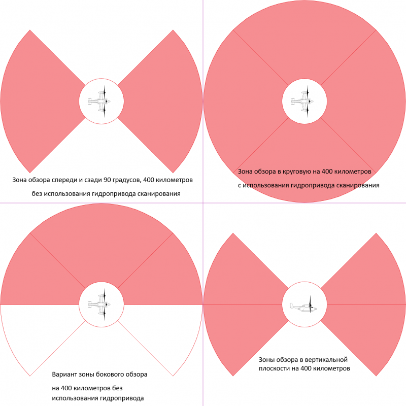
Let’s assume that our AWACS tiltrotor performs a combat mission at an altitude of 5–7 thousand meters at a speed of 500 km/h, which means that it will be in the visibility zones of onboard 3D-RLK locators at least 300 kilometers from the ship, providing direct communication lines like control of the UAV itself, as well as data transmission lines for intelligence information from on-board locators.
By adding to the estimated tiltrotor flight radius of 300 km around the ship's location another 400 km of the detection range of onboard locators in a side view, we get a decent increase in the radar reconnaissance zone, comparable to the capabilities of the carrier-based Hawkeye AWACS aircraft, and certainly exceeding similar parameters in hypothetical use helicopter AWACS Ka-31.
If you create an unmanned tiltrotor AWACS, following the path of least resistance, then it is logical to borrow for it, without changes, ready-made serial airborne radars with AFAR NO36 “Belka” from the Su-57 fighter. But the optimal product for a fighter does not fully meet the requirements of AWACS. Based on publicly available information about the fighter's radar, it has a needle-shaped radiation pattern with a width of 2,3 by 1,8 degrees in perpendicular planes with geometric dimensions of the AFAR of 0,7 by 0,9 meters.
For an AWACS tiltrotor with the same element base and range, a product that is 20 percent more powerful with a symmetrical diagram in both planes of 2 degrees and geometric dimensions of 0,8 by 0,8 meters is preferable. True, this will require an increase in the transmitting and receiving elements in the AFAR from 1 to 526 units. The previous sample of the NO1 Irbis radar stated viewing angles in azimuth and elevation of ±898 degrees (electronic) and ±35 degrees (hydraulic).
It should be noted that when the beam is electronically deflected in one of the planes by 60 degrees, its directional pattern width doubles. Therefore, in order to maintain acceptable accuracy characteristics on our radars, we will keep the electronic scanning of the beam within the generally accepted limits of ±45 degrees with the addition of scanning the AFAR body in the horizontal plane to the same ±45 degrees using a hydraulic drive.
Features of the tiltrotor project include the desirable use of engines with controlled thrust vectoring, which will ensure greater stability of the device when performing takeoff and landing operations on a ship, and the installation of simple skids instead of retractable wheeled landing gear, which will create minimal resistance in flight and are much lighter and more reliable will fix the aircraft on the rocking deck of the ship.
Combat use options
The ship provides air defense/missile defense/anti-aircraft defense from a threatening direction on the approach to the naval base of the fleet or patrolling the “bastion” of SSBN duty. A single destroyer is capable of creating a closed access zone for enemy aircraft, both attack and patrol types, while simultaneously monitoring the underwater situation using one or two gas launchers, spaced by diving depth and ranges, and the bow sonar in passive mode.
If there is a need to expand control zones, both in the air and under water, or to increase efforts in a certain direction, on-board AWACS tiltrotors and ASW helicopters are connected. At the same time, control of near-Earth space is being carried out in order to prevent the enemy from conducting space reconnaissance during a threatened period, from active jamming to the physical destruction of enemy satellites in low areas of circumpolar orbits.
The ship is deployed in a given area as a missile arsenal for the CRBD. Moreover, depending on the season and ice conditions in the area, this may be a joint voyage with one of the icebreakers of our fleet. And then it is quite possible to create a threat to NATO Scandinavians from beyond the 75th parallel in the northern regions of the Greenland and Barents seas, and to American-Canadian officials and generals of the North American NORAD from the Baffin, Beaufort and Chukchi seas. Using the unlimited autonomy of a nuclear destroyer, it is possible to plan trips and small submarines under its cover to both coasts of North America, and even more so to the shores of Foggy Albion and the Land of the Rising Sun.
The ship becomes the basis of zonal air defense of any order of ships of our fleet in conducting strike, anti-submarine, and landing operations.
The ship is the calling card of Russia and displays our flag in any area of the World Ocean, both to provide support to friendly countries and to put pressure on the enemy.
Freshness of caronimica
Be that as it may (in the sense of whether destroyers will be built in Russia or not, whether they will be nuclear or smoke the sky, whether they will be made of foil or with an armored deck), the time has come to bring a fresh spirit to the names of ships. For the northeast, I propose a series of ship names that emphasize the inviolability of Russian sovereignty over the islands of the Pacific Ocean and at the same time are a natural irritant for potential adversaries.
The symbolism of the name of the nuclear-powered armored destroyer can be justified by the following fact: on each of the islands there is an active volcano that erupted after 1945. A volcanic eruption is comparable to a ship's missile salvo.
Volcano Islands:
O. Matua (Sarychev Volcano - 2009);
O. Onekotan (Krenitsyn Volcano - 1952);
O. Kunashir (Tyatya volcano - 1981);
O. Iturup (Kudryavy volcano – 1999);
O. Simushir (Zavaritsky volcano - 1957);
O. Paramushir (Ebeko volcano – 2022).
The author does not object to traditions. What’s wrong with a series of five-letter names “small peoples of Russia” in the spirit of the well-known gunboat “Koreets”: “Abkhaz”, “Ingush”, “Buryat”, “Karel”, “Chechen”, “Chuvash”, “Evenk”, “ Nenets", "Koryak". Or the “historical series”: “Bolshevik”, “Chekist”, “Volunteer”, “Oprichnik”, “Robber”, “Boyarin”.
But first we need to lay down the ships!
Articles from this series:
Nuclear-powered armored destroyer PRO/PLO
Information