Left alone. Prototypes of French engineering vehicles from the 1920s–1930s
Taking into account the experience of the battles of the last world war, in the early 20s of the twentieth century, the French military, like most of the military in the world, continued to work on the creation of machines that were supposed to provide increased maneuverability and the ability to immediately or in a minimum time overcome tanks and other combat vehicles such natural and artificial obstacles on the battlefield as rivers, canals, ditches, ravines, scarps, etc.
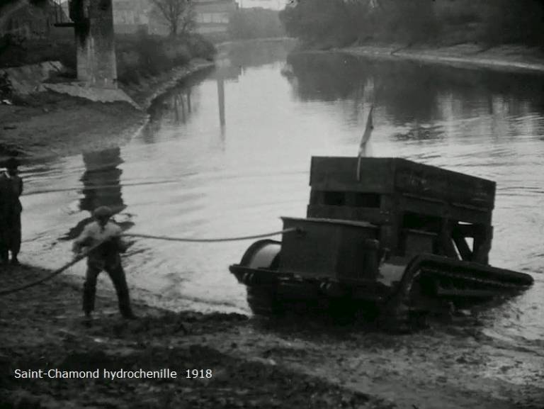
Crossing device "Saint-Chamon"
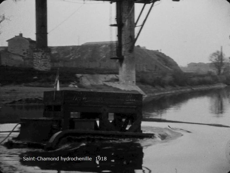
The crossing device was intended to serve as a support for the bridge when crossing the river.
It was developed by the Compagnie des Forges et Acieries de la Marine et d'Homecourt (French Engineering Enterprise), or FAMH for short, in 1918.
Structurally, the device consisted of two vehicles on the chassis of the Saint-Chamond tank.
One machine was to serve as a bridge support, and the second was a standard Saint-Chamond tank, converted to generate and supply power to the bridge support.
The bridge support was a rectangular metal platform mounted on a modified hull of the Saint-Chamond tank.
At the same time, it should be pointed out that this movable support, in fact, was a remotely controlled machine that moved due to an electric motor. The current to the engine was supplied by wires from the second, standard version of the tank, which remained on the shore.
Preparation of the power supply line to the support machine and the entry of the bridge support into the water
This pair of vehicles was supposed to follow the advancing armored vehicles as closely as possible and provide the tank units with a transverse element (support) for a pontoon or assault bridge.
In the prospect of an offensive in the north of France and Belgium, in areas with many small rivers and streams, the need for such means to ensure the crossing was obvious.
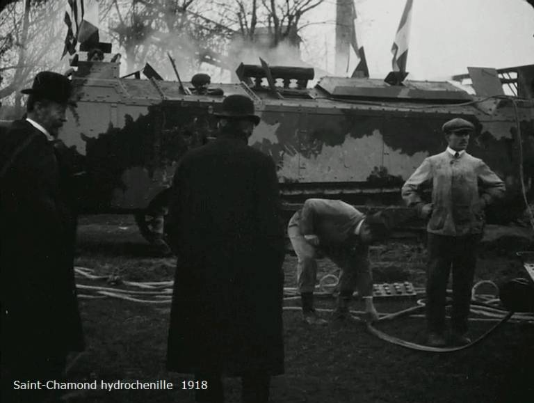
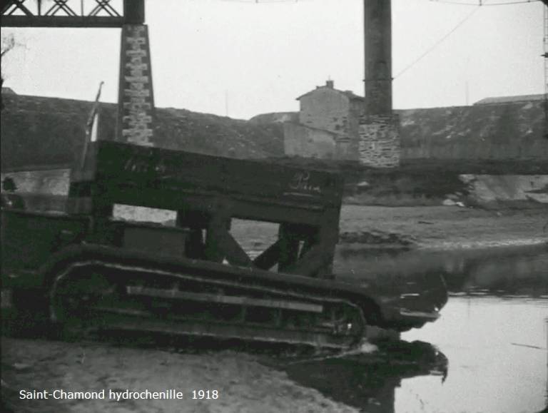
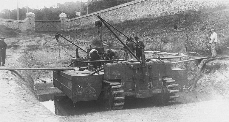
The bridge pier comes out of the water after testing. Givor, November 1918
This equipment was tested in Givor (eastern France, south of Lyon) on November 14, 1918.
However, the imminent end of hostilities put an end to further tests, and the system was never put into service.
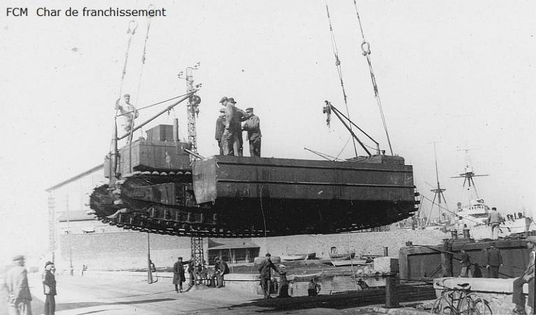
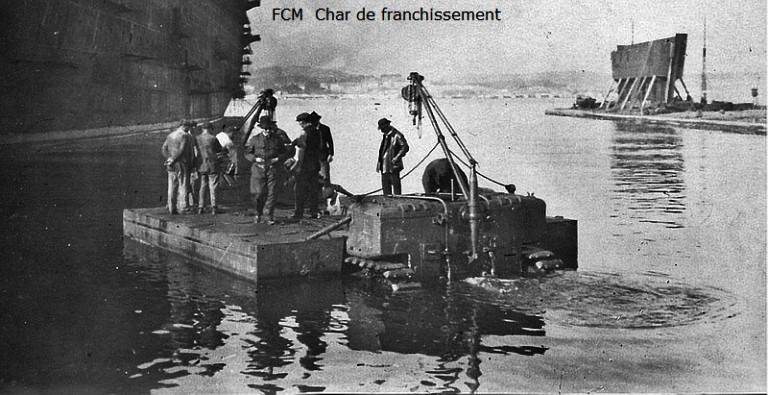
FCM ferry tank
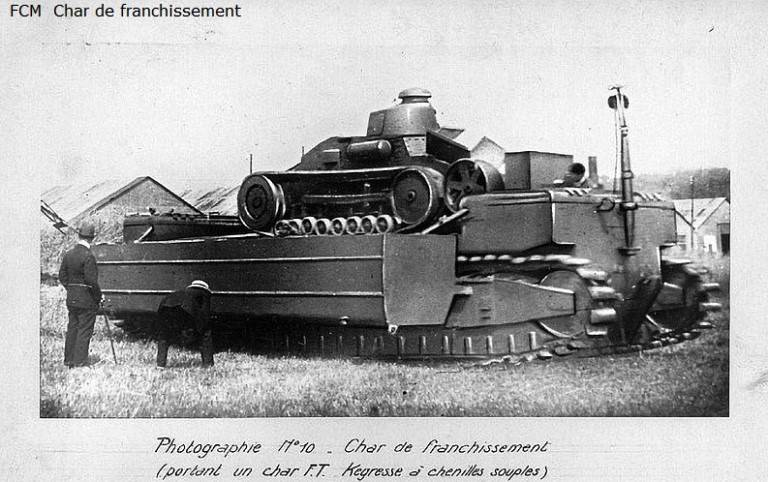
Already after the war, in 1920, as part of the program to create a machine for overcoming (in French terminology - “crossing”) water obstacles, FCM (Forges et Chantiers de la Méditerranée) was given the task to develop such special equipment.
At the end of the same year, the company began to create a prototype of the future ferry.
Despite the fact that the prototype of the “cross chariot” (Char de franchissement), as the designers dubbed the ferry, was ready by the middle of 1923, testing of this machine began only in 1926.

Delivery of a ferry tank (ferry) for testing
The tank originally had a length of 12 meters, which was later increased to 14 meters. At the same time, the width of the car was also increased - from 2,6 to 2,7 m.
The ferry car was intended for crossing rivers and straits of cars and armored vehicles, primarily tanks.
The ferry tank consisted of a leading vehicle or a middle pontoon and two extreme pontoons, which are stacked on the middle one during transportation. At the crossing, the extreme pontoons are laid out on the sides of the central one with the help of cranes, forming an integral structure of the ferry.
Movement on the water is carried out due to the propeller and rewinding of the tracks.
The car was equipped with a 150 hp engine. With. The payload was about 14 tons.
The speed of the car was insignificant: no more than 4 km/h on the road and 2 km/h on the water.
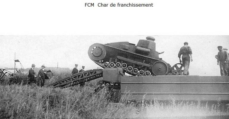
Loading experienced tank Renault NC2 on the ferry. It is interesting to note the presence of additional wheels in the bow of this tank to overcome wide trenches and ditches.
Preparation of the FCM ferry tank for entering the water (end pontoons are open) and checking the ferry on the water
From 1927, it turned out that the transport capabilities of the FCM were not enough for the new generation of tanks that appeared, such as the "B" or "D2" tanks.
In addition, a ferry with a carrying capacity of 22 tons, developed in the interests of the engineering troops, appeared on the horizon. This event called into question the use of a very expensive and less economical tank.
Around 1930, the FCM project was abandoned.
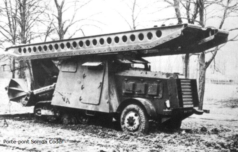
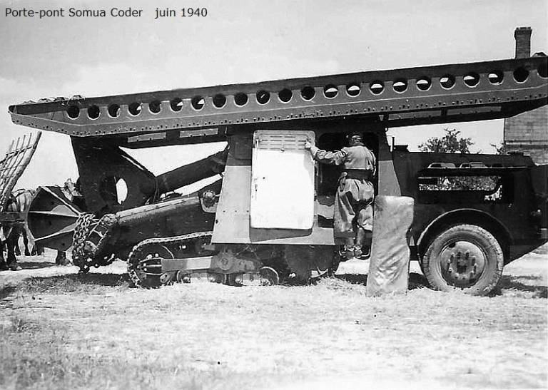
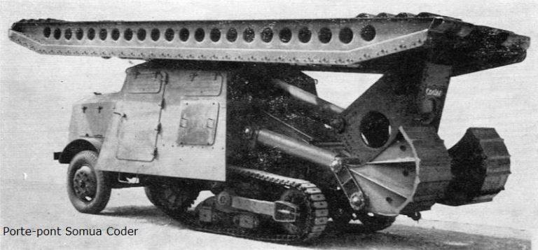
SOMUA CODER mechanized bridgelayer
The development program of the French army for 1926 provided that a battle tank should overcome trenches (ditches) 2,5 m wide, and heavy tanks - 4,5 m.
But in practice, everything turned out to be much more complicated.
So, the reference length of the caterpillar of the heavy tank B1 bis had a length of only 2,75 m, the average D1 - 2,20 m, and for the light H35 and H39 - only 1,80 m. All this could not satisfy the tasks set by the 1926 program of the year .
It was from this point of view that the Société Coder of Marseilles was commissioned in 1937 to study an assault bridge that could be built over an obstacle 6 to 7 m wide (for example, through the "dragon's teeth" (stone gouges) of the Siegfried line, the parallel lines of which would run the entire length of the bridge).
From the very beginning, the bridge was designed as a hydraulic overturning type. Such a scheme was first implemented by the British in 1918 and has since been adopted by all the armies of the world.
The prototype bridgelayer was built in 1938, and it was tested from September to December of that year.
In August 1939, this single copy was handed over to the French army for further testing.
At the beginning of 1940, the tests were completed. Based on their successful results, it was decided to start mass production.
However, the German attack on France and the defeat meant the end of the program on this bridge.
Whether this bridgelayer took a direct part in the battles of 1940 for France is unknown.
But the fact that he fell unscathed into the hands of the Germans in June 1940 is a fact that confirms the photo below.
The question remains open as to why the Germans did not set in motion the further development of the equipment that was already ready and passed all the tests.
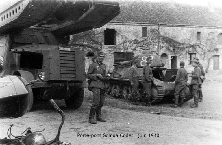
Captured in June 1940 by the Germans SOMUA CODER
Structurally, the whole machine is divided into two parts: the transport-laying machine and the bridge itself.
More precisely, they planned to install at least two types of bridge on the car. But, most likely, it was decided at first to build only one type of bridge, the one shown in the photo.
The vehicle was one of many variants of the base SOMUA MCL-5 (or M 226-5) semi-tracked tractor that were constantly changing.
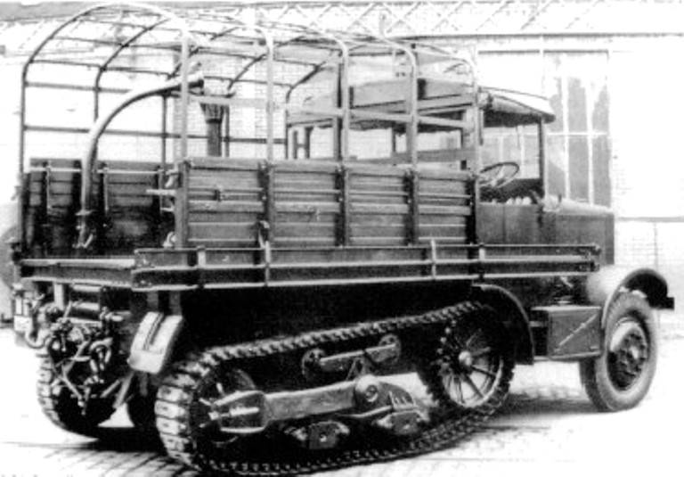
Half-track tractor SOMUA MCL-5
The tractor was introduced in 1933 to tow the 155 GPF with a 4 L 6,5-cylinder monobloc engine producing 85 hp. With. Some got the FE engine: hence the name of the 6-cylinder MFECL-5 tractor, which eventually gave it the name "MSCL-5 type", with the S standing for "six cylinders".
This engine, which, after a slight alteration, could run on lean gas or diesel, developed a power of 105 hp. With.
It was on this MSCL-5 that the bridge carrier for CODER was mounted.
An auxiliary motor shaft was installed on the bridgelayer on the gearbox to drive the pressure oil pump of the 4-cylinder lifting device. He was fed from a special oil tank.
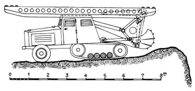
The engine and transmission were located in front of the conveyor, and the cab with the crew was in the middle of the car.
The bridge and equipment for its installation were located in the aft part of the bridgelayer.
Above the rear of the undercarriage was a false undercarriage, elongated from riveted sheet metal, supporting on each side blades made of plates, which were used to set the machine before the bridge was raised. Two cylinders corresponding to each of these shovels were used to lower or raise them.
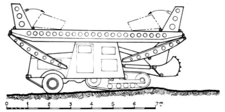
View of the aft mast layer. You can clearly see the cylinders and supporting blades that fall to the ground when the bridge is raised.
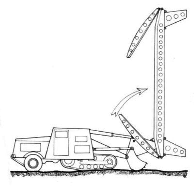
The algorithm for laying the bridge was as follows.
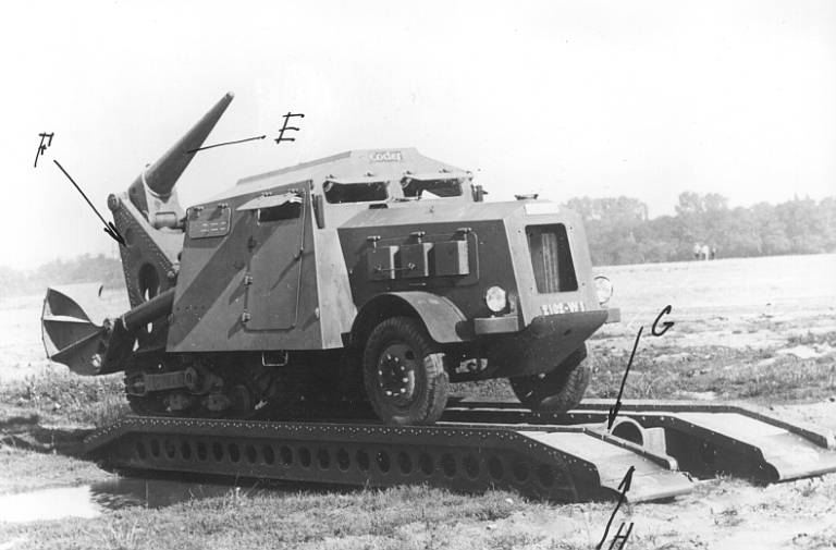
In the axis of the machine, a large cylinder, called a folding cylinder, pressing on the triangular scarf of the bridge (F - photo below), raised it vertically. Its horizontal installation was completed by another cylinder placed inside the kerchief. This cylinder had a tapered punch (letters G and E in the photo below) on which a bridge was screwed.
After installation and moving forward, the machine released this punch from the body.
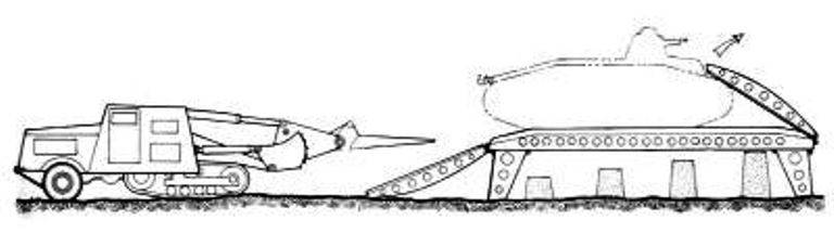
After passing equipment through the bridge, the conveyor also crossed it. And already on the other side he raised the bridge, being stern to it.
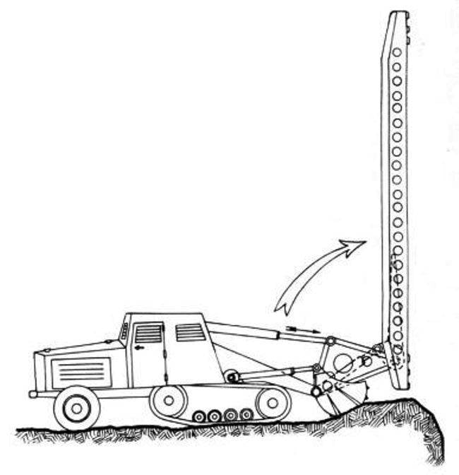
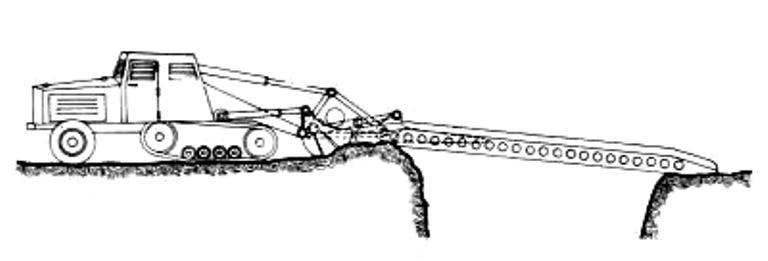
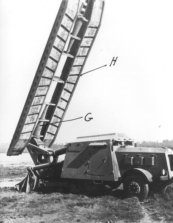
The sequence of installing the bridge on the barrier
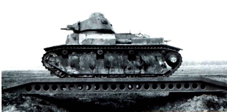
Photos showing the passage of equipment on the bridge and the moment the bridge was removed from the barrier
The entire front of the vehicle, the hood and the control and maneuvering cabin were armored with steel sheets 5 and 10 mm thick, located at small angles.
The cabin should have had at least two seats, if not three, but it is quite possible that 4 people could be accommodated there.
In any case, none of them had to leave the cabin to install or remove the bridge, which was facilitated by the mechanization of the entire process.
A 5- or 7-ton winch was installed on the conveyor.
It was also possible to adapt a Gauthier crane with a lifting capacity of 1,5 tons or a gantry crane with a span of 4 m and a lifting capacity of 2 tons to it.
Finally, an anchor shovel could be included with the machine, allowing the winch to lift twice as much weight.
The bridge consisted of two rectangular track beams 60 cm wide, connected by seven struts. At the ends of the beams were beveled to facilitate the entry and exit of equipment from them.
During tests carried out from 1939 to 1940, the bridge proved to be able to support the weight of Type B tanks (32 tons). Armament, as well as means of communication, was absent on the car.
To monitor the battlefield, six viewing hatches were used: two in the front sheet, one in each door and a hedgehog, one on each side of the control compartment.
The average loaded speed of a bridge layer with a trailer varied from 15 to 18 km/h, and with a trailer weighing from 15 to 20 tons it could reach 32 km/h.
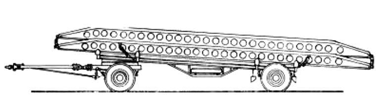
Trailer SOMUA CODER with two stowed axles
The main performance characteristics of the bridge layer:
The crew of the car - 2-4 people
Length with bridge - 8,2 m
Length without bridge - 7,7 m
Width - 2,44 m
Own weight of the machine – 9 t
Payload mass - 1,5 t
Booking - 5-10 mm
Bridge length - 8 m
Bridge width - 2,2 m
The carrying capacity of the bridge is 20 tons.
The figures below show a possible second version of the bridge, its design and method of installation on the Dragon's Teeth anti-tank obstacle.
The sequence of installation of the second type of bridge on the barrier
Thus, in the period between the world wars, French military engineers developed original engineering vehicles that were in many ways ahead of other armies in the world.
Thus, vehicles like the FCM ferry tank, that is, self-propelled ferries such as the French EWK-Gillois or the Soviet PMM ferry-bridge vehicle, appeared only thirty years later.
And the option of a bridge tank, similar to the Saint-Chamond crossing device, but at the same time controlled by the crew, was developed by the British only at the end of the Second World War.
Information