Experimental gidrolet Be-1
Designers and engineers from the start stories The development of water transport sought to give ships the ability to move with the greatest speed. For this, it was necessary to reduce the resistance created by the vessel during its movement on water. As a result, the logic of speed chase led to the most radical solution - to exclude body contact! The embodiment of this idea became possible after the creation of WIG - ships, "based" on the wings.
The ekranoplan is a vehicle that moves along a flat stretch of earth or water surface (screen) using a screen effect. The screen effect is an increase in aerodynamic lift and a decrease in drag at a height commensurate with the wing chord.
The screen effect has been known for a long time. The "forefathers" of ekranoplans were ships on a static cushion and with "air lubrication" (280 years ago, Swedish scientist Swedenden suggested using air to reduce drag when the ship was moving). Work on the study and practical application of this effect was carried out not only by shipbuilders, but also by aircraft manufacturers. The former were interested in the screen effect as a means of increasing the speed of the ships, and the latter as a means of expanding the tactical capabilities of the military and increasing the efficiency of civil aircraft.
For the first time, the aviators met with the influence of the screen in the middle of the 1920-ies, drawing attention to the behavior of the aircraft directly on the ground during landing and take-off: contrary to the known laws of classical aerodynamics, an additional rather significant lifting force arose from the earth.
With such a manifestation of the screen effect learned to fight. Airplanes equipped with interceptors, which allowed the pilot at the right time to worsen the wing aerodynamics and thereby cause the machine to fall for landing.
However, the prospects for using the screen effect were very tempting. The first experimental ekranoplan was built by a Finnish engineer T. Kaario in 1935. Kaario developed an ekranoplan idea up to 1964 and created a number of various devices and their modifications.

To date, in many countries, on the basis of theoretical and experimental research, many experimental WIGs have been built. But it should be noted that in the development of this type of technology, domestic designers and scientists were particularly successful.
In the Soviet Union, one of the first works devoted to the influence on the aerodynamic properties of a wing of a shielding surface was the experimental work of Yuryev B.N. (1923 year). In the USSR, the first practical development of WIG in the USSR was accomplished in the second half of 1930 by the famous inventor PI Gorokhovsky.
However, the work of Gorky Central Design Bureau on the SEC (Central Design Bureau for hydrofoil vessels) and its chief designer Alekseev R.Ye. received the greatest and well-deserved fame in this area. But such studies were carried out not only by Gorky designers.
Ekranoplans since the beginning of 1960. engaged designers OKB Beriev G.M. (Taganrog). Of the research projects carried out in Taganrog, it is necessary to mention the project of an EK-plane-aircraft carrier and a family of very large E-winged-winged telescopes developed under the guidance of A. Bogatyrev.
Beginning with 1963, a series of experimental studies were carried out on the topic of ground-effect vehicle in the Central Aero-Hydrodynamic Institute to study the layout of an airplane of the catamaran type with underwater wings. For the two-boat scheme, several options were chosen for the hydrofoils, made according to the four-point scheme.
In the first variant, which received the designation "A", the underwater nasal wings were placed in front of the center of mass, and the feeding ones - behind the center of mass. The mode of motion of a hydrocranoplane from hydrofoil ships is distinguished by the fact that at high speed the mass of the apparatus is balanced by the lifting force created by the wing of small elongation.
The motion of the hydrocranoplane takes place on the air wing and the nose hydrofoil, as a result of which the stern submarine “hangs” in the air. In the TsAGI hydrochannel, such a mode of motion was impossible to fully simulate, and therefore the tests were divided into three stages.
Not at the first stage, towing tests were carried out at the institute's experimental pool at a speed of up to 12 meters per second. The purpose of this stage was the selection of the optimal scheme of underwater wings. After that, a large-scale towed model was tested at speeds up to 20 meters per second in an open pond.
The final stage was to be the production of a large-scale self-propelled model of an WIG-aircraft carrier for the study of the adopted scheme of hydrofoils, as well as seaworthiness, stability and controllability.
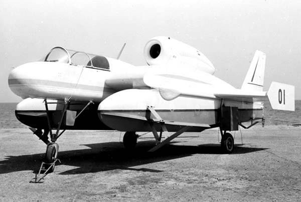
The first two stages were to be conducted at the Central Aero-Hydrodynamic Institute. Two models were built at TsAGI - the 6313 Model on the 1 scale: 7 and the 6320 Model on the 1 scale: 4. The layout of the latter was used as a base for the manufacture of a manned model. Its construction was entrusted by the GM Beriev Design Bureau. This operating model in the design bureau was named "Hydrolet", in official documents it was assigned the index Be-1.
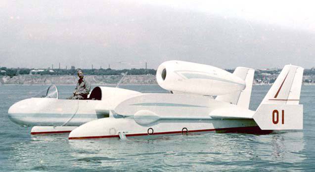
Hydrolet was developed by an initiative group of young designers. It was made almost entirely of wood. The power plant is a Czechoslovak turbojet М701С-250.
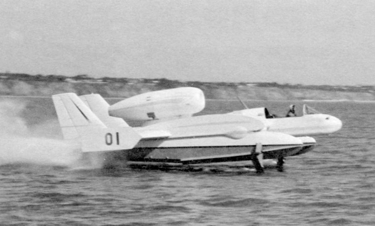
During the tests, which took place in June-October 1965, in the waters of the Taganrog Bay, test pilot Kupriyanov Yu.M. on a gidrolet developed speed 160 km / h.
Total committed 16 outlets to the sea. In the displacement mode, eight runs were conducted on hydrofoils — forty; on the air wing with flaps rejected by 20-25 degrees — forty-three. The installation angle of the front wings was 4 degrees, aft - 0 degrees. The rear wings before the second exit to the sea were set at an angle of 2 degrees, however, this did not pay off, and they were returned to their original position. The tests were carried out in calm and on the wave height of 0,4 meter.
The testers noted that the strong jets of water reaching the inter-shell space from the floats create the impression that the apparatus comes out of the water thanks to them rather than hydrofoil.
To reduce the gap between the water surface and the rear edge of the wing, the center-wing flap chord was almost doubled. This significantly increased the lift created by the wing.
The air wing and hydrofoils were able to create a lift force, which was only 60 percent of the total weight of the hydro-fly, although, according to calculations of thrust, it should have been enough to output the Be-1 hydro-fly to the on-screen flight in which the hydrofoil is not activated.
In OKB Beriev G.M. on the basis of the Be-1 hydro-flight work, the Be-11 passenger hydro-crane crane designed for the 100 passenger seats was designed. The mounting options for the Be-11 of two AI-20 engines or four NK-7 turbojets or four M337 engines were studied. However, the work beyond the preliminary calculations for the project did not go.
Flight technical characteristics of the experimental hydrolyte Be-1:
Wingspan - 6,00 m;
Length - 10,37 m;
Engine type - Walter MHNUMXC-701 turbojet;
Traction - 8,7 kN;
Maximum speed - 160 km / h;
Crew - 1 man.
The ekranoplan is a vehicle that moves along a flat stretch of earth or water surface (screen) using a screen effect. The screen effect is an increase in aerodynamic lift and a decrease in drag at a height commensurate with the wing chord.
The screen effect has been known for a long time. The "forefathers" of ekranoplans were ships on a static cushion and with "air lubrication" (280 years ago, Swedish scientist Swedenden suggested using air to reduce drag when the ship was moving). Work on the study and practical application of this effect was carried out not only by shipbuilders, but also by aircraft manufacturers. The former were interested in the screen effect as a means of increasing the speed of the ships, and the latter as a means of expanding the tactical capabilities of the military and increasing the efficiency of civil aircraft.
For the first time, the aviators met with the influence of the screen in the middle of the 1920-ies, drawing attention to the behavior of the aircraft directly on the ground during landing and take-off: contrary to the known laws of classical aerodynamics, an additional rather significant lifting force arose from the earth.
With such a manifestation of the screen effect learned to fight. Airplanes equipped with interceptors, which allowed the pilot at the right time to worsen the wing aerodynamics and thereby cause the machine to fall for landing.
However, the prospects for using the screen effect were very tempting. The first experimental ekranoplan was built by a Finnish engineer T. Kaario in 1935. Kaario developed an ekranoplan idea up to 1964 and created a number of various devices and their modifications.
To date, in many countries, on the basis of theoretical and experimental research, many experimental WIGs have been built. But it should be noted that in the development of this type of technology, domestic designers and scientists were particularly successful.
In the Soviet Union, one of the first works devoted to the influence on the aerodynamic properties of a wing of a shielding surface was the experimental work of Yuryev B.N. (1923 year). In the USSR, the first practical development of WIG in the USSR was accomplished in the second half of 1930 by the famous inventor PI Gorokhovsky.
However, the work of Gorky Central Design Bureau on the SEC (Central Design Bureau for hydrofoil vessels) and its chief designer Alekseev R.Ye. received the greatest and well-deserved fame in this area. But such studies were carried out not only by Gorky designers.
Ekranoplans since the beginning of 1960. engaged designers OKB Beriev G.M. (Taganrog). Of the research projects carried out in Taganrog, it is necessary to mention the project of an EK-plane-aircraft carrier and a family of very large E-winged-winged telescopes developed under the guidance of A. Bogatyrev.
Beginning with 1963, a series of experimental studies were carried out on the topic of ground-effect vehicle in the Central Aero-Hydrodynamic Institute to study the layout of an airplane of the catamaran type with underwater wings. For the two-boat scheme, several options were chosen for the hydrofoils, made according to the four-point scheme.
In the first variant, which received the designation "A", the underwater nasal wings were placed in front of the center of mass, and the feeding ones - behind the center of mass. The mode of motion of a hydrocranoplane from hydrofoil ships is distinguished by the fact that at high speed the mass of the apparatus is balanced by the lifting force created by the wing of small elongation.
The motion of the hydrocranoplane takes place on the air wing and the nose hydrofoil, as a result of which the stern submarine “hangs” in the air. In the TsAGI hydrochannel, such a mode of motion was impossible to fully simulate, and therefore the tests were divided into three stages.
Not at the first stage, towing tests were carried out at the institute's experimental pool at a speed of up to 12 meters per second. The purpose of this stage was the selection of the optimal scheme of underwater wings. After that, a large-scale towed model was tested at speeds up to 20 meters per second in an open pond.
The final stage was to be the production of a large-scale self-propelled model of an WIG-aircraft carrier for the study of the adopted scheme of hydrofoils, as well as seaworthiness, stability and controllability.
The first two stages were to be conducted at the Central Aero-Hydrodynamic Institute. Two models were built at TsAGI - the 6313 Model on the 1 scale: 7 and the 6320 Model on the 1 scale: 4. The layout of the latter was used as a base for the manufacture of a manned model. Its construction was entrusted by the GM Beriev Design Bureau. This operating model in the design bureau was named "Hydrolet", in official documents it was assigned the index Be-1.
Hydrolet was developed by an initiative group of young designers. It was made almost entirely of wood. The power plant is a Czechoslovak turbojet М701С-250.
During the tests, which took place in June-October 1965, in the waters of the Taganrog Bay, test pilot Kupriyanov Yu.M. on a gidrolet developed speed 160 km / h.
Total committed 16 outlets to the sea. In the displacement mode, eight runs were conducted on hydrofoils — forty; on the air wing with flaps rejected by 20-25 degrees — forty-three. The installation angle of the front wings was 4 degrees, aft - 0 degrees. The rear wings before the second exit to the sea were set at an angle of 2 degrees, however, this did not pay off, and they were returned to their original position. The tests were carried out in calm and on the wave height of 0,4 meter.
The testers noted that the strong jets of water reaching the inter-shell space from the floats create the impression that the apparatus comes out of the water thanks to them rather than hydrofoil.
To reduce the gap between the water surface and the rear edge of the wing, the center-wing flap chord was almost doubled. This significantly increased the lift created by the wing.
The air wing and hydrofoils were able to create a lift force, which was only 60 percent of the total weight of the hydro-fly, although, according to calculations of thrust, it should have been enough to output the Be-1 hydro-fly to the on-screen flight in which the hydrofoil is not activated.
In OKB Beriev G.M. on the basis of the Be-1 hydro-flight work, the Be-11 passenger hydro-crane crane designed for the 100 passenger seats was designed. The mounting options for the Be-11 of two AI-20 engines or four NK-7 turbojets or four M337 engines were studied. However, the work beyond the preliminary calculations for the project did not go.
Flight technical characteristics of the experimental hydrolyte Be-1:
Wingspan - 6,00 m;
Length - 10,37 m;
Engine type - Walter MHNUMXC-701 turbojet;
Traction - 8,7 kN;
Maximum speed - 160 km / h;
Crew - 1 man.
По материалам сайта airwar.ru
Information