Crossing rivers. Post-war pontoon equipment Royal Engineers
post-war era
The end of the Second World War eased the workload at the Christchurch engineering center to some extent, allowing for a major reorganization.
This process culminated in March 1946 when the three wartime institutions in Christchurch, i.e. the Bridge Construction Experimental Establishment, the Demolition Experimental Establishment and the Tunneling Experimental Establishment, were merged into the Military Engineering Experimental Establishment or MEXE.
On March 22, 1946, Brigadier General G. R. Mikan became the new institution's first chief superintendent, succeeding Colonel J. Hunt. Colonel Hunt has been the Superintendent of the EBE (Experimental Bridging Establishment) since the new establishment became responsible in September 1941 for the research and development of all engineering equipment for sappers, expanding its traditional role of constructing bridges only.
Since that time, the tasks of the center have also included the creation of equipment necessary for the construction of military roads and airfields, for supplying troops with fuel, water and electricity in the field, for mine equipment and destruction, as well as to satisfy the ever-growing interest in mechanical handling and earthmoving installations.
To enable the center to carry out its tasks, in the late 1940s it was reorganized into four groups: "Bridge Construction", "Roads and Airfields", "Electrical and Mechanical Group", and "Explosives Group". All of these groups worked closely with the Weapons Research Establishment at Fort Halstead, Kent.
In 1946, bridge engineer Sir Donald Bailey was knighted for his valuable contribution to the Allied victory. In the same year he was awarded an honorary Doctor of Engineering degree from the University of Sheffield and became Associate Director of MEXE.
In 1957, D. Bailey became the first civilian director of MEXE, which he was rightfully proud of.
But back to bridges.
The crossing equipment, developed during the war, was designed primarily to transport vehicles weighing no more than class 40. But the flexibility of the Bailey bridges made it possible to carry large loads without much loss of efficiency, given the improvised methods developed to increase the width of the roadway of this and some other equipment.
However, the constant increase in the weight and size of machines, combined with the lessons learned during the war, highlighted the need for new and more efficient equipment. To this end, a number of War Department specifications were issued shortly after the war, predominantly on class 15/24 and 50/70 designs.
The main elements of the new equipment program were class 15/24 and 70 floating assault bridges, class 24 and 70 fixed or dry support bridges, as well as a 50/70 class raft and auxiliary elements such as an overhead crane, a high bridge and a fast tug.
Initially, work on the new crossing equipment was slowed down by the Christchurch reorganization mentioned above, and also by the general post-war reorganization of the civilian technical staff of the Ministry of Supply.
However, in 1946 design of a Class 15/24 floating bridge and a Class 70 fixed bridge was begun, and during this period valuable work was completed on a number of projects that were underway at the end of the war.
Before considering the new equipment in more detail, it is necessary to mention the impact of new materials on the design of the bridge itself.
By the end of the war, the situation with the supply of aluminum alloys had improved considerably, and attention was paid to their use for those bridge components in which significant weight savings could be expected.
For example, the Mark 2 Close Support Raft version used light alloys to a minor extent through the use of cast light alloy deck panels and welded light alloy road supports.
Raft CSR Mark 2
The main advantage of light alloys is that their density is about one third that of steel, but with a strength 60% higher than that of mild steel.
On the other hand, the lower elastic force of light alloys is a disadvantage, which means, for example, that an alloy beam requires a greater depth of section than a similarly loaded steel beam to prevent excessive deflection.
To illustrate the possible savings in weight, experimental light alloy transoms for the SWBB (standard widened bailey bridge) were made immediately after the war.
The use of light alloys for the transoms as well as the stringers in the SWBB, together with the possible reduction in deck thickness as a result of the increased strength of the stringers, resulted in a weight reduction of 1,14 tons per 10-foot (3,05 m) bridge span.
During the war, the development of alloyed steels did not go unnoticed.
The Bailey Bridge during the war used high-strength steel with a working strength 50% higher than mild steel and good weldability. Thanks to the development of manufacturing technologies, even stronger steels became available for new bridges, the strength of which was 85% higher than that of mild steel.
Other materials, such as plastics and resin-impregnated wood, were also considered, and a series of small trials explored their possible use.
After World War II, thanks to the great abundance of raw materials and the availability of modern alloys, a number of improved rafts and ferries were developed in a very short time, including the Light Assault Raft and the Light Assault Floating Bridge or LAFB.
18th grade experimental raft
Taking advantage of more readily available materials, an experimental class 1945 raft was developed in late 18, very similar in concept to the CSR (Close support raft) raft, but for the first time using light alloy for the main beams of a bridge or raft.
The beam panels were truss-shaped and riveted structures fastened together at the top and bottom of each panel to form four continuous beams for the superstructure of the raft. The ramps consisted of tapered panels and were linked together using a conventional balancing mechanism. Cast alloy deck panels were made similar to those of the CSR Mark 2.
The Class 18 raft used four double-ended Mark 5 pontoon piers. Although the raft was not retired from the prototype stage due to the end of the war, it provided valuable experience in the use of light alloys for building military bridges.
Class 18 experimental raft, similar to the Class 9 closed leg raft, but with braced and riveted light alloy beams
Experimental light alloy pontoon
Another experimental piece of equipment that made full use of the new materials was the light alloy pontoon.
It was developed towards the end of the war for use with standard bridging equipment such as the Bailey and CSR in the Far East theater.
The intention was to provide a pontoon that could be transported not only in conventional road transport, but also in transport aircraft and gliders.
The complete pontoon consisted of three separate sections: bow, intermediate and center sections. During transportation, the short nose was inserted into the intermediate one. In this case, the two sections weighed about 600 pounds (270 kg) and were about 10 feet long when connected.
The center sections, using rubber pads to maintain water resistance, had folded sides to reduce the overall depth of the section when transporting. The 11-foot (3,34 m) center sections weighed about 800 pounds (360 kg). The connecting bolts were suitably coated steel, but aluminum alloy was used for everything else.
The frame was made from extruded or rolled profiles using light alloy castings where needed. The pontoon was covered with 16 mm thick aluminum sheet.
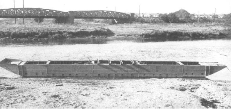
Experienced light alloy pontoon
pontoon bailey
After the war, work also continued to improve the Bailey floating bridge.
The floating supports for the BRV (Bailey pontoon bridge) class 40 consisted of two central sections with intermediate and bow sections at each end. Three of these piers were used for each span of the 42-foot (12,7 m) bridge. Six of these piers were used to support the Class 40 bridge landing pad.
More than 150 central sections were made, as well as about 130 intermediate and bow sections, but the massive introduction of the pontoon was prevented by the development of new assault floating bridges.
New pontoon equipment
The pontoon bailey was a superior bridge in many ways, and a floating version of the standard Class 1947 widened bailey was produced in 80.
But in fact, it could not be considered an assault bridge.
The 50/60 class raft, designed for crossing the Rhine, had the distinct advantage that the bridge girder panels were folded on the pontoon deck and simply had to be hinged to a vertical position before being connected to panels on the next pontoon.
This principle could be applied to the construction of an entire bridge, as well as to the construction of a single raft, which was demonstrated in 1950 for the new 15/24 and 70 class floating assault bridges.
Light assault pontoon bridge
Already at the beginning of 1947, a draft design of a new class 24 floating bridge was submitted to the Chief Engineer for consideration.
This was due to the requirement for the rapid construction of a bridge capable of transferring all the equipment and equipment of an entire infantry division across a water barrier (although not immediately).
In November, the basic concept of a truss bridge with panel beams supported on double-skinned piers was adopted, which was eventually converted to a Class 30 Light Assault Floating Bridge (LAFB).
The head of the project was Bruce Boswell (in other Boswell sources), who during the war was an officer in one of the engineering units, and later became the head of the institution in Christchurch.
The idea behind the bridge was remarkably simple.
Here is how J. Chester describes it in his book Military Bridges:
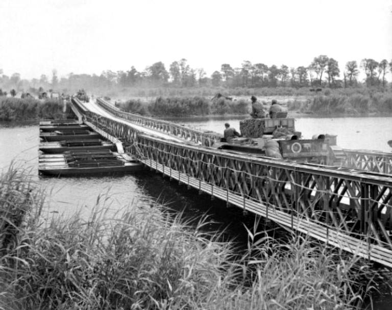
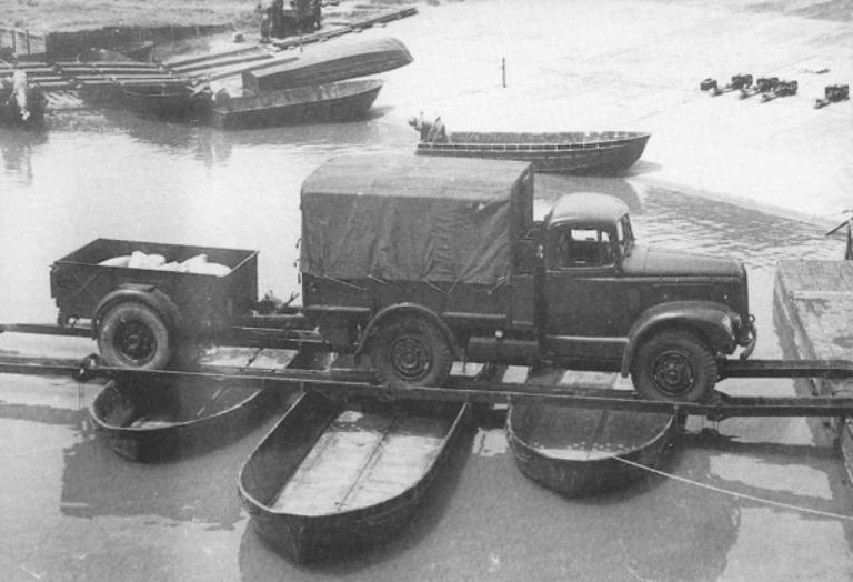
“The 3-ton vehicle carried two pontoons, 17 feet 6 inches (5,32 m) long and 5 feet 9 inches (1,75 m) wide, which could be connected to form a two-part pier (pontoon) including roadway into the pontoon deck. Two more pontoons, forming the second pier, were transported on a special single-axle trailer towed by a 3-ton vehicle.
On the bridge, the piers were spaced 12 feet 6 inches (3,8 m) apart so that each full truck and trailer provided 25 feet (7,6 m) of floating bridge. The pontoon panel was hinged to each pontoon deck and, once raised into position, formed part of the main distribution beam. The deck sections were then positioned to overlap the gunwales of adjacent pontoons. Footpaths 2 feet 6 inches (0,76 m) wide were provided along the edges of the bridge. The bridge's roadway width was 11 feet (3,34 m) between curbs.
At each end of the bridge, four tightly connected pontoon legs formed a landing pad raft that supported the sea end of a 27-foot (8,2 m) landing pad constructed from plain and pontoon panels, transoms, deck sections and various small special pieces.
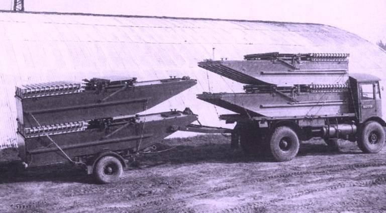
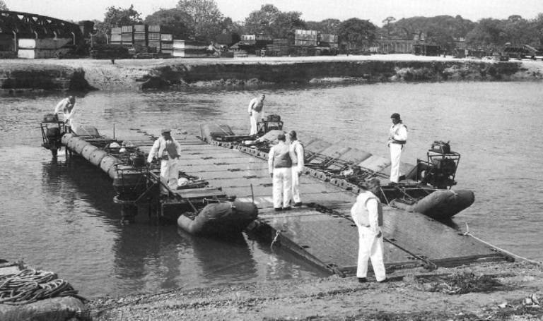
Pontoon Transportation Light Assault Floating Bridge
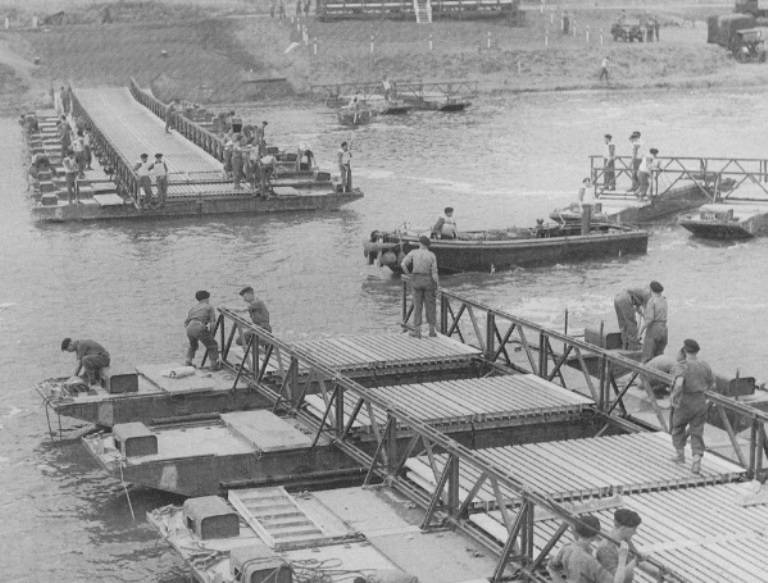
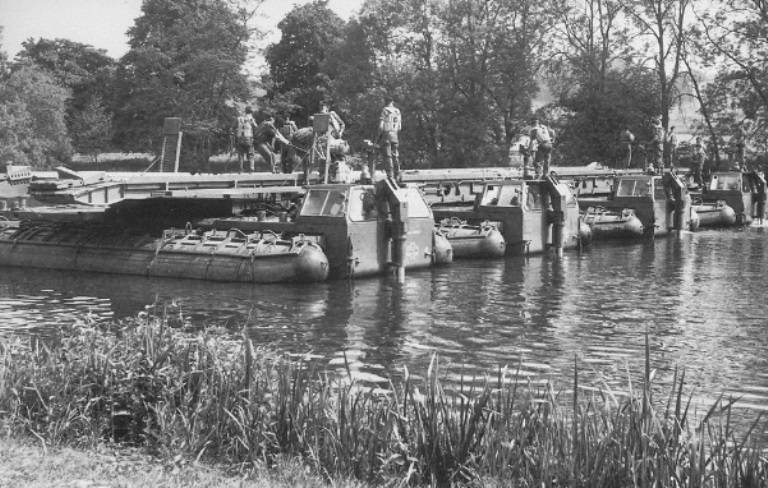
Assembly of a light assault floating bridge, 1948, Chatham
Light assault pontoon bridge assembly
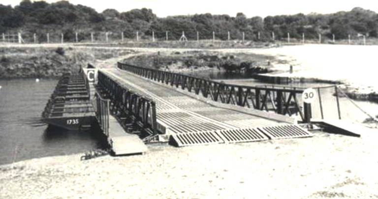
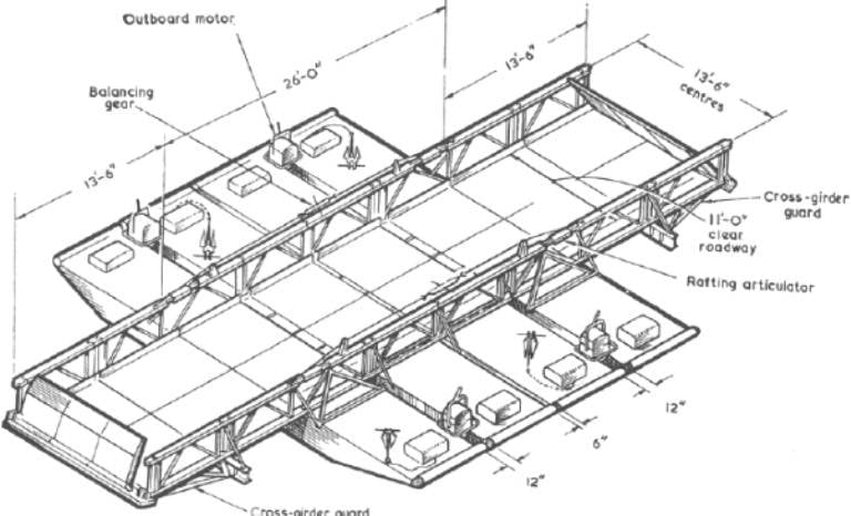
The LAFB was the first military bridge to use hydraulic articulators to adjust the height of the landing pads. The articulators allowed the landing pads to articulate freely during slow changes in water level, but lock automatically whenever a vehicle crossed the bridge.
These mechanisms could be manually operated and inserted into the upper belt of distribution beams at each end of the bridge between the actual bridge supports and the landing area.
The bridge made full use of new materials, the pontoon was made entirely of light alloy, and the transoms of the landing areas were made of light alloy profiles. The 6ft 3in x 3ft (1,9 x 0,91 m) belts and diagonals of the panels were made of high strength steel.
Light Assault Raft LAR
The pontoons of the LAFB bridge can be formed into a class 12 light assault raft using four closely connected legs, or a class 30 raft using seven pontoons. Hydraulic joints were not used to raise and lower the raft's ramps, as they were relatively slow.
Instead, a balance gear was used along with rafting articulators through which panel pins were inserted to take up the load once the ramps were in the correct position. The rafts were powered by standard outboard motors.
Light Assault Raft Class 12
Mock-up tests were carried out at MEXE in 1948, but it was not until 1954 that full-scale military tests were conducted at BAOR and Canada.
Further inevitable delays followed, and the first nine sets of equipment were delivered to the troops only in March 1958.
During a demonstration on a water barrier, the 350-foot (106,4 m) bridge was built in 65 minutes. This was a good time, given that it had previously taken 75 minutes for a trained unit working under similar conditions to build a similar bridge.
The raft was transported by a light platoon of the RASC bridge company, which included twenty three-ton trucks and trailers. This company was capable of building a 460-foot (140 m) bridge, four Class 30 rafts, or five Class 12 rafts.
The equipment was designed for staged installation in separate and well-dispersed areas using at least two overhead cranes with a lifting capacity of 7 tons, bulldozers for site and approach preparation, and motor tugs to service two pier rafts after they are submerged.
Although the LAFB was designed primarily for the assault role, it was replaced in the early 1960s with amphibious bridge equipment, or, in our opinion, self-propelled ferries. Thereafter it became known as the Light Floating Bridge or LFB and the raft as the Light Raft or LR.
In the early 1960s, eight versions of the fiberglass-reinforced plastic pontoon were made, mainly to assess the vulnerability to damage and ease of repair of this relatively new material. Most of these pontoons were sent to the Far East for evaluation in tropical climates.
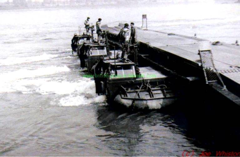
The video below shows soldiers building the LAFB bridge across the Thames as part of an army exercise. Military engineers lower massive pontoons down the river and then the latter are connected, forming a half-bridge. Then this half-bridge is rafted down the river and connected to the other half of the bridge coming from the opposite bank.
Heavy assault floating bridge HAFB
Almost immediately with the LAFB bridge, its enlarged version was developed, which was called the Heavy Assault Floating Bridge or HAFB (heavy assault pontoon bridge).
This bridge was introduced in the early 1950s, but it was only put into service in 1962. In the 50s of the twentieth century, amphibious bridge equipment (self-propelled ferries) looked more acceptable.
The small design team responsible for developing the bridge was led by Dr. Philip Bulson, a former military engineer officer who served as head of the research center in Christchurch from 1974 to 1985.
The HAFB was intended to complement other types of crossing equipment for the transfer of all class 80 divisional transport across the water barrier and, in addition, to transport class 100 cargo with some restrictions on the distance between vehicles and at reduced speeds. The actual production equipment was rated as Class 80 (tracked) or Class 100 (wheeled) with no speed limit.
The bridge's concept was to increase the size of the LAFB bridge, and the main difference from the LAFB was the introduction of a much larger pontoon pier to handle more substantial loads. Center spacing was 17 feet (5,17 m) compared to 12 feet 6 inches (3,8 m) for the LAFB.
The pontoon of the bridge consisted of 3 sections: a central section and two bow sections.
The central pylon structure was made of aluminum alloy while the two bow pontoons were made of mild steel, although early prototypes used plywood construction for these bow pontoons.
The center section was transported on a 10-ton vehicle, and the two bow sections were transported on a trailer, which was used to launch the entire section into the water.
The width of the roadway between the curbs was 15 feet (4,56 m), while the LAFB was 11 feet (3,35 m). The landing bay was extended to 37 feet 9 inches (11,47 m), its river end supported by four three-piece pontoons. As in the case of the LAFB, hydraulic articulators were used, adapted to the rise (up to 1,97 m) and fall (up to 0,76 m) of the river level relative to the bank line.
Heavy Assault Floating Bridge components: A - couplings, B - power supply, C - ramp (ramp), D - propulsion pontoon, E - main pontoon, F - floating pontoon (buoy-pontoon)
The other main difference between LAFB and HAFB was that HAFB used an aluminum alloy for the beam panels, a first in English bridge building.
In the past, beam panels were made from steel because welding was the most efficient way to transfer heavy loads from clamp blocks to the core members of pinned panels, and aluminum alloy welding available at the time was impractical.
However, in the case of the HAFB, significant deflection of the main beams was necessary to ensure proper buoyancy of the pontoon legs. To achieve this deflection with a steel beam would require too large gaps between the pin holes or very shallow and therefore heavier panels.
This problem has been avoided by using aluminum alloy panels, which have a much lower Young's modulus than steel and thus allow the beam to sag more.
Note. Young's modulus is a mechanical characteristic of materials that determines their ability to resist longitudinal deformations and fixes the degree of material stiffness.
The HAFB center pontoon was transported on a 10-ton GS six-wheel bridge truck. The same vehicle towed the FV 5A four-wheeled 2861-ton trailer previously used with Heavy Ferry. The trailer was loaded with two bow pontoons.
The bridge set consists of eighteen of these floating compartments, as well as two additional 10-ton trucks and trailers carrying supplies for the landing sites. A complete set can provide a 322-foot (98 m) bridge.
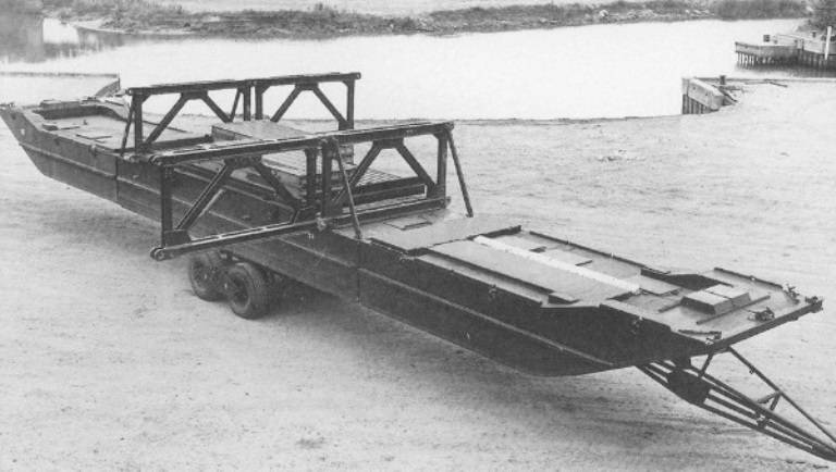
Heavy assault floating bridge pontoon on its four-wheeled trailer
In general, the method of construction was similar to that of the LAFB.
Much of the work was done in pre-assembly using overhead cranes and then outrigger well before H-hour. This avoided the accumulation of troops and vehicles at the site of the actual bridge, although, of course, the landing sites had to be arranged in advance.
Construction proceeded at a rapid pace, and during the exercise, the 61-meter river bridges were typically completed in about 1 hour and 20 minutes, day and night.
The design approval certificate was issued at the beginning of 1959, and in 1962 the bridge entered service with the British troops in Germany. It was intended primarily for the crossing of heavy tank The Conqueror, which weighed 65 tons, entered service in 1955 as the heaviest and largest gun tank ever produced in the UK.
However, few such tanks were built (185 serial units).
By the early 1960s, the 54-ton Chieftain appeared on the horizon, entering service in 1966. Thus, it became necessary to consider the project of a class 60 pontoon for this tank. This version offered a shortened three-piece pontoon pier using a conventional center pontoon and two shortened bow pontoons.
The pontoon pier had to be pre-assembled away from the bridge site and then towed to the river using a standard trailer. A pre-assembled boarding bay, or PALB, has also been proposed, using collapsible bow pontoons to reduce width when traveling on the road.
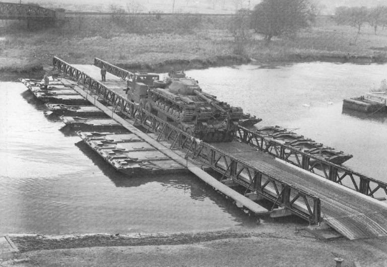
Class 100 Heavy Assault Floating Bridge testing using a Conqueror tank on a transporter
This modified version of the HAFB would reduce the need for overhead cranes and eliminate the need for a pre-assembly area, which would also greatly speed up construction time.
Although one prototype PALB for testing was built at ROF Woolwich, and preliminary tests were carried out at the MEXE factory, the advent of amphibious bridges in the early 1960s ended this idea.
But the manufactured PALB prototype generated a lot of interest at MEXE because it was the first bridge equipment to make extensive use of the new aluminum, zinc and magnesium alloys.
Shortly after development of the Class 60 version of the HAFB ceased, the word "assault" was dropped from the name of the pontoon equipment, as was the case with the LAFB.
The bridge became simply known as the Heavy Floating Bridge or HFB.
Heavy Ferry
A further development of the HAFB bridge was the 50/70 Heavy Ferry or HFy class ferry.
Design work on it, sometimes referred to as the Class 80 Heavy Ferry, began under Major A. Wycombe as early as 1947, when tanks began to gain weight again.
Troop trials of the HFy began in 1955, and the first serial ferry entered service at the end of 1957.
Preliminary work on the pontoon began as early as 1946 and was carried out for a year on a steel pontoon with a wooden deck. During the course of the work, it was decided that a bow loading raft had many advantages over a side loading raft such as a 50/60 class raft. By 1950, a pilot model of such a raft had been built at MEXE.
By this time, the Conqueror heavy tank (FV 214) was entering service, and so the required capacity of the raft was increased to class 80.
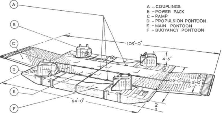
In its final form, as a class 80 heavy ferry, the raft consisted of three separate parts: the main pontoon, the outer buoyancy pontoons, and the propulsion pontoon.
The light alloy main pontoon was designed to carry any load up to class 80 (83,5 t) and had a hydraulically operated 20-foot (6,08 m) ramp permanently hinged to the pontoon's bow.
The pontoon itself had a square stern, and four such pontoons could be connected together to make up the ferry's main body, 64 feet (19,45 m) long and 15 feet (4,56 m) wide, with a 20-foot ramp at either end.
The buoyancy pontoons (letter F in the picture below) were 16 feet (4,86 m) long and were needed to provide extra buoyancy to the ferry, and their flush decks could only carry light cargo.
The pontoons of the propulsion system (letter D in the figure below) ensured the movement of the ferry at a speed of 6 knots when loaded or 7,5 knots when unloaded.
The Gill system, powered by a Rolls Royce B80 Mark 5L engine, was chosen as the jet propulsion system. An axial flow pump drew water through an inlet grate at the bottom of the pontoon into a U-tube and then pushed it out again through the guide vanes as a jet at an angle of 15° to the horizontal.
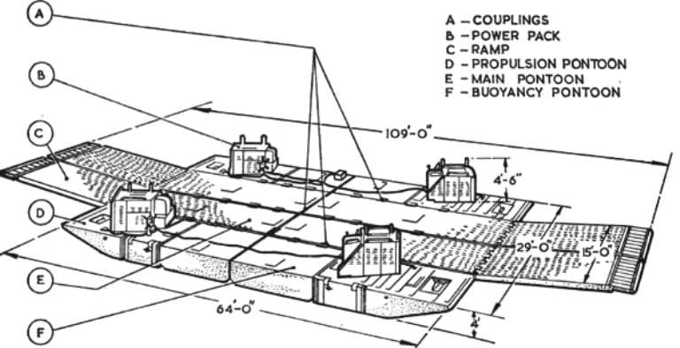
General view and components of a heavy ferry
Various pontoons were connected together in the water by means of spring-loaded self-acting arms to form a ferry with a roadway 15 feet (4,56 m) wide and an overall length of 109 feet (33,14 m).
The strength of the ramps and their hydraulics was such that the ferry could operate with a loaded 3-ton GS truck placed on each pair of ramps, cantilevered, leaving room on deck for four more such vehicles.
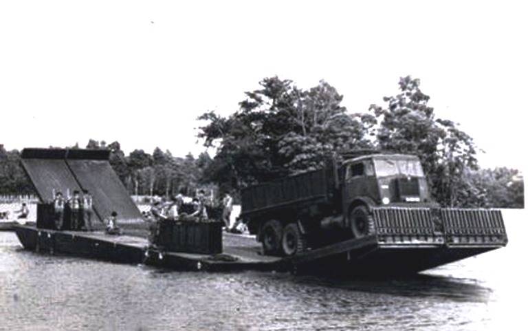
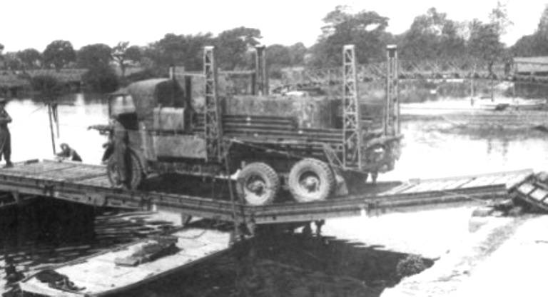
Class 80 heavy ferry with a 3-ton truck during testing
Four 10-ton GS trucks were used to transport the main pontoons, each of which carried one of the propulsion pontoons and towed the main pontoon with the ramp folded down on a special four-wheeled 5-ton FV 2861A trailer, from which the pontoon could descend directly into the water.
Two GS 3-ton trucks were used to haul four buoyancy pontoons.
Propulsion and buoyancy pontoons could be unloaded by an overhead crane or towed from trucks using special unloading ramps.
The pontoons could then be floated or towed (thrown) on a sled by a bulldozer through the terrain and then pushed into the water, since they were all equipped with thick bottom skin and towing eyes.
Heavy Ferry has gone a long way in solving the problems of moving support assets through water barriers in a timely manner to provide the necessary assistance to troops in the beachhead.
This is how the ferry is described on the RE Museum website:
“A ferry, under good conditions, can be built in an hour, and if necessary, at a considerable distance from the main line of attack and then put into action exactly where and when it is necessary ...
These pontoons connected in the water using spring-loaded self-acting arms to form a free ferry with a 15-foot (4,5 m) wide, 109-foot (32,7 m) long roadway from one end of the ramp to the end of the other ramp. The Heavy Ferry helped solve the problem of carrying heavy support equipment across water to allow attacking infantry to fend off enemy counterattacks.
In good conditions, a ferry can be built in an hour. It was capable of carrying six 3-ton GS trucks, three 10-ton GS trucks or, of course, a main battle tank. He could make ten circuits per hour through a 400-foot (120 m) water barrier, carrying one tank, or eight trips back and forth with a mixed load of vehicles.
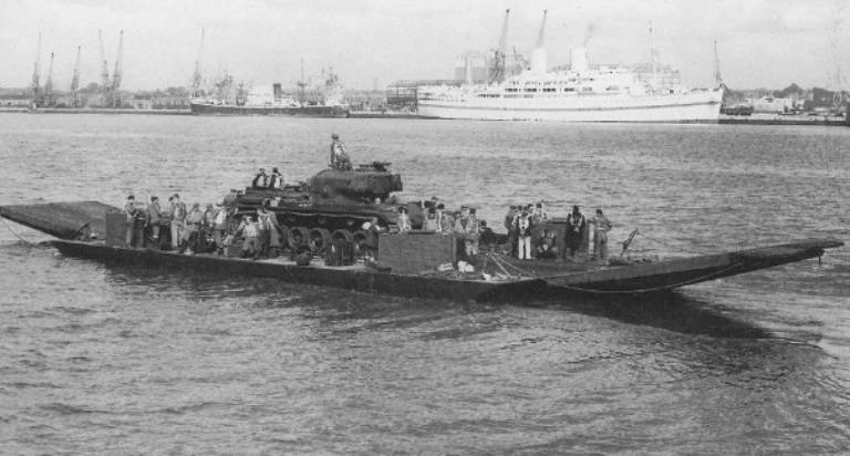
Heavy ferry testing at Southampton Waters using a Centurion tank as a test load
Infantry assault boat raft
After the war, various options were discussed for adapting the Mark III assault boat to carry infantry equipment during river crossings. With the advent of the Mark IV assault boat after the war, the use of a rafting boat was again the subject of considerable experimentation, the goal of which, as stated in 1956, was to create a quickly built class 6 raft (up to 8 tons).
The Mark IV boat was 5,32 m long and 1,82 m wide, compared to the Mark III's 5,06 by 1,65 m, but had a slightly reduced payload.
In the mid to late 1950s, a series of trials were conducted to find a suitable raft composition, despite the fact that in late 1957 the infantry decided that the need for an assault boat raft no longer existed. One such test in 1958 used four different superstructures, each mounted on two pontoons formed by joining the stern of two Mark IV assault boats.
Superstructures tested included improvised wooden versions (with both fixed and hinged ramps) and a modified FBE Mark III car raft. In addition, various ways of installing superstructures were considered, namely, directly on the gunwale, on flyovers located at the bottom of the supports, and on a saddle fixed across the gunwale.
In 1961, the infantry again turned their attention to this project, and the technical specifications were drawn up for it: the raft was to be a class 6 using four Mark IV assault boats and have a 28-foot (8,51 m) clear deck. Colonel R. Weld, a former combat engineer officer who had previously served in MEXE and now returned to the institution as a scientific civil servant, was placed in charge of the project.
Early testing at MEXE indicated that the end-loading raft would be difficult to operate at current speeds in excess of 2,5 knots (4,6 km/h), and design continued on the basis of a side-loading raft with a specially designed superstructure. The superstructure consisted of two track tracks installed directly on the gunwale of the boat. Each track was formed from two inner sections with parallel sides and two sections of a tapering ramp, all sections being fastened together at the level of the upper and lower chords so that the ramps could not turn freely.
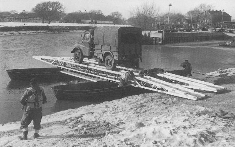
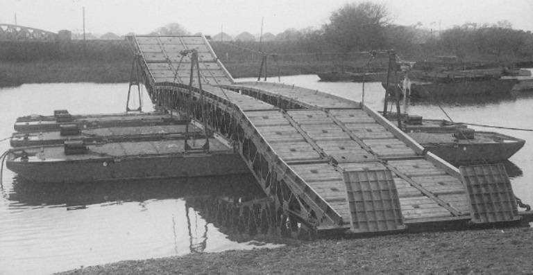
Prototype infantry assault raft 6th class,
using Mark IV assault boats
using Mark IV assault boats
Despite satisfactory testing of the prototype raft, the infantry once again decided that such a raft was neither demanding nor necessary, probably in light of more pressing requirements for other equipment and a limited budget.
The raft of the Far Eastern assault boat
With the start of the military coup in Borneo in December 1962, the British Commonwealth brigade, acting in support of the forces of the Sultan (loyal to the British), found itself without a suitable raft with which to transfer light equipment through the many water barriers encountered in the Borneo jungle.
So Major J. P. Fitzgerald-Smith, an innovative sapper who was then an employee in the workshops of the engineering base in Singapore, made the construction of a simple overpass from aluminum alloy sheet. Such a guide could be attached to the side of army all-terrain vehicles and used so that the vehicles could cross deep monsoon drains along the main roads and thus easily enter the jungle.
To overcome the rafting problem, Fitzgerald-Smith adapted the guides for use with the Mark IV assault boat to form a Class 3 raft. The two boats were butt-joined to form a single pier. Two more boats were used on either side of the central pier. Then, along the gunwale of two single and double boats, two sections of the overpass were laid and firmly attached to the handrails of the boats with long hook bolts. At the ends of the overpass, sections of the track were hinged, which formed the ramps of the side loading raft. In this case, the ramps were raised and lowered manually and fixed in position using a simple articulation.
Far East assault boat raft, 3rd class version using Mark IV assault boats
The raft movement problem was solved with a Seagull Outboard Motor (OBM) purchased from the local market!
The raft proved to be very successful, but was largely a local catch and was not actually used except in the Far East. The Class 6 version used two two-man Mark IV assault boats and four overpasses.
Amphibious equipment
After the war, some preliminary work on amphibious bridge equipment was carried out, which focused mainly on adding flotation devices to existing vehicles.
In the early 60s, this idea evolved into a requirement for an amphibious bridge that could haul Class 400 cargoes at about XNUMX feet per hour and also have the flexibility to operate as a raft under its own power.
It should be noted that some experiments with a modified tracked vehicle, which included flip floats for buoyancy and a deck for transporting light vehicles, were carried out during the war. However, the idea was not developed beyond the simple prototype stage and remained dormant.
In the early 1960s, this idea was considered again, and a requirement was specified for landing-bridge equipment, the time of construction, lifting and dispersal of which would be compatible with the conditions imposed by modern weapons and surveillance systems.
The goal was to build a Class 60 bridge at about 400 feet (121 m) per hour under working conditions and with as few people as possible. In addition, class 60 rafts were required to be built with the same equipment in less than 30 minutes. The estimated time of commissioning of such pontoon equipment is 1965.
The idea of an amphibious bridge was attractive.
The advantage would be that the bridgelayers would themselves be mobile, would have considerable maneuverability, would be self-propelled in the water, and would be able to quickly join together to form a bridge, and each could carry its own squad of sappers acting as drivers and crew members.
In this way, the concentration of people and logistics vehicles on the bridge section could be avoided. Given the likely areas of fighting in West Germany, this was a reasonable disadvantage and the idea was further developed.
On the other hand, the pieces of equipment will be entirely dedicated to connecting on the water. For such work, a specialized machine is required. Obviously, it will be quite complex and, therefore, expensive to purchase and maintain equipment.
Unfortunately, the British did not have such equipment even on the drawing board, and, accordingly, preliminary work was not carried out on MEXE.
But the French had it - this is a self-propelled ferry EWK-Gillois. The British got access to it, and the Royal Engineers created a test group.
In the summer of 1960, several British officers were seconded to Germany, where American specialists from the US Army Engineering Research and Development Laboratory were completing the study and testing of the EWK-Gillois ferry car. The American Army provided valuable assistance in training the British test team, which soon returned to Britain to carry out further tests on the three bridges and two ramp units that had been ordered by the War Office.
The delivery of the ordered number of vehicles to the British was carried out in January and March 1961.
After that, extensive testing began at the Combat Vehicle Research and Development Center (FVRDE), the Signals Research and Development Center (SRDE) and the No. 8 Maintenance and Repair Center.
Amphibians were tested at the mouth of the Solent River and on the Thames. They were coordinated by MEXE under the direction of J. Barnickel, a full-time engineer officer who served in MEXE and then retired from the army as a major to become a scientific civil servant. J. Barnickel later became project manager for M2 and ten years later led an international concept study team working on the Bridge to the 80s project.
It should be noted that the British were lucky to significantly reduce testing in the UK, taking into account the 1959 report of the US Army Engineering Research and Development Laboratory on this equipment, which was provided by MEXE, as well as the report of the West German Federal Army on testing two self-propelled ferries .
Gillois equipment testing on the Thames, 1961
Designed by French Army officer Colonel Jean Gillois and manufactured by the German company Eisenwerke Kaiserslautern, the EWK-Gillois was an ingenious, multi-functional and completely unique concept. The machine was specially designed to support advanced combat units in overcoming water (and not only) obstacles.
The amphibian is put into working condition in a few minutes, and it can do it on the way to the river or the sea.
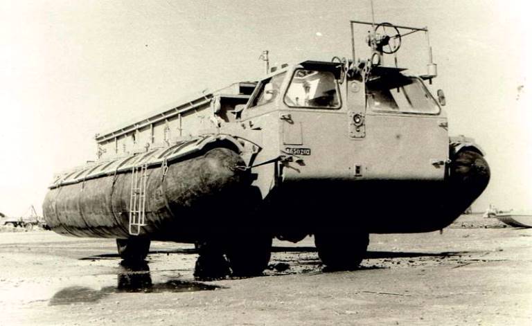
Self-propelled ferry EWK-Gillois in trials
Essentially, the Gillois bridge was a four-wheeled amphibious vehicle weighing 29 tons, with a crew of 2 and a class 36 (up to 40 tons for tracked vehicles), equipped with an engine and suspension system, which made it suitable for both road and water.
Buoyancy and stability on the water have been increased by installing pneumatic floats on each side of the vehicle. The floats were tied to saddles, which first had to be attached to mounting brackets on each side of the hull. The floats were then inflated using an automotive air compressor. Each rig had a team of four people who needed about 30–40 minutes to get the rig ready to enter the water.
Rigging work was usually carried out at a considerable distance from the river.
The width of the prepared car with fully inflated floats was 19 feet (5,78 m), the length of the ferry excluding the length of the ramps was 7,96 m, the width of the carriageway was 4 m.
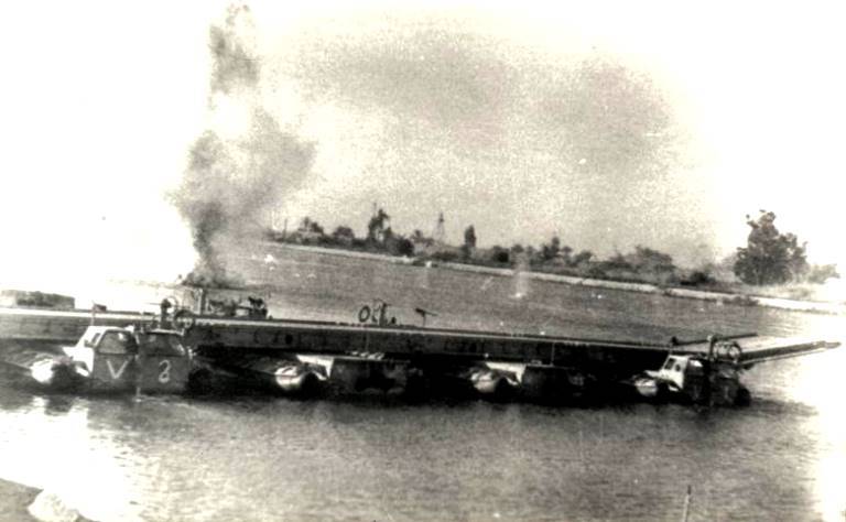
Ferry Gillois on a water barrier during an exercise
Once in the water, the road wheels were fully retracted into the body of the vehicle. Movement in the water was provided by a rudder propeller, which was mounted at the top in front of the machine when driving on the road, and then turned in an arc of approximately 270 ° and lowered to work in the water.
In addition to 12 bridge machines, the set includes 6 Gillois Ramp Unit (ramp machine) or Carrier machines. This car carried the bridge ramp, consisting of two (not three) sections 7,96 m long.
Once the Ramp Carrier entered the water, the ramp pivoted and expanded in a manner similar to a bridge superstructure. After that, Carrier delivered its hydraulically controlled ramp to the bridge or ferry, it was disconnected from the car. The fact that this amphibious vehicle was not used on the bridge was considered a serious lack of equipment.
There was a third Gillois unit known as the Ferry Unit which was similar to a block bridge but did not use a superstructure. A 16-foot (5 m) ramp was permanently mounted at the rear of the vehicle, allowing vehicles to be loaded and unloaded along the amphibious axis directly onto the deck. The carrying capacity of the Ferry Unit was class 20 (up to 22 tons).
Three such ferry units were purchased by the US Army for trials, but a purchase from the UK was not considered.
The amphibious bridge or self-propelled ferry Gillois entered service in October 1961.
And already in May 1962, the work of the Royal Engineers began with amphibious equipment for building bridges. 1 Detachment from 50th Field Squadron was converted to the 23rd Landing Troop for the river crossing, equipped with seven Gillois ferry vehicles capable of providing a pontoon bridge about 184 feet (55,9 m) long.
In 1963 the detachment was reorganized into the 23rd Amphibious Engineer Squadron, commanded by Major J. L. Booth, with one Gillois detachment, one field detachment, workshops and headquarters.
But soon the German alternative to Gillois, the M2 self-propelled ferry, appeared on the horizon.
The Ministry of Defense decided to purchase German bridge and crossing equipment in much larger volumes.
Detachment Gillois of the 23rd Amphibious Engineer Squadron in PPD
...and in exercises
Thus, in the fifteen years after the war, several excellent new bridges were built by English engineers.
However, in the early 1960s, the requirements for new and more sophisticated equipment were finally defined, in particular for a medium-sized girder bridge, an air transport bridge, and amphibious bridges.
But more on that in the next concluding section.
To be continued ...
Information