Allied Secret Airplanes of the Wartime (Part 1) - Vought V-173
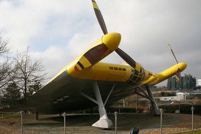
In 1940's, American engineer Charles Zimmerman (not to be confused with his German namesake) designed a unique aerodynamic plane that still amazes not only with its unusual appearance and unique aerodynamic design, but also with flight characteristics. For its unique appearance, the aircraft received many nicknames, among which are the Flying Pancake, Flying Parachute, Shimovka Zimmerman. Nowadays, it is safe to say that this plane, along with the German Fi-156, was one of the first vertical / short take-off and landing vehicles.
History create
In 1933, the famous American aerodynamic scientist, Charles Zimmerman, carried out a series of experiments with a wing of small elongation. Conducted theoretical studies have demonstrated the effectiveness of this scheme. According to his idea, at the ends of the wing of ultra-low elongation there should have been screws that would be turned in the direction opposite to the direction of rotation of the air vortices descending from the wing. This made it possible to reduce the inductive resistance of the “wing-screws” system and build a machine with a large range of speeds. At the same time, the use of low-speed large-diameter propellers with sufficient power capacity would allow the machine to take a vertical take-off and hang in the air, like a cross-section helicopter, and low drag would increase the flight speed.
The first manned model of this scheme with a wingspan of 2 meter Zimerman built in 1935 year. The model was equipped with two cleon air-cooled engines for 25 hp. This model was never able to get off the ground due to the inability to achieve synchronization of the rotation of the screws. After that, Zimmerman designed a new rubber-motor model with a wingspan of 0,5 meters. This model has successfully flown. After that, the designer achieved support at NASA, where before that his designs were rejected as too modern. In the summer of 1937, the designer was invited to work for Chance-Vout. Here, taking advantage of the great potential of laboratories, Charles Zimmerman was able to build a V-162 electrolyte with a wingspan of an 1 meter. This electrolyte successfully flew in the hangar.
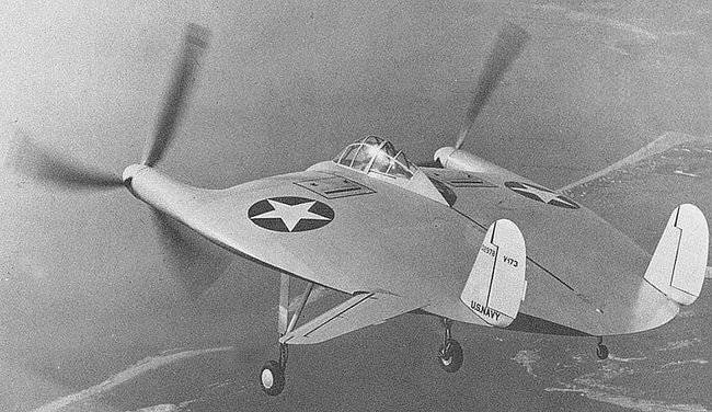
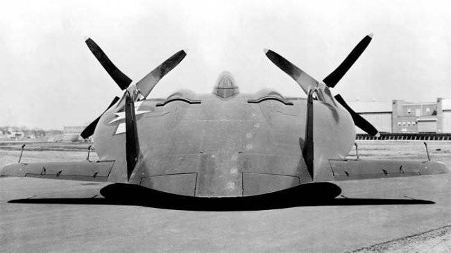
The following year, the military was interested in Zimmerman’s development of 1938, and at the beginning of 1939, he took part in a competition to create an unconventional fighter. Works under this competition were funded by the US Navy. It was then that Zimmerman set about creating a light-V-173 aircraft. This aircraft had a rather complicated wooden structure, which was covered with fabric. The model was equipped with 2-I synchronized engines "Continental" A-80 horsepower 80. These motors rotated the 2 huge three-bladed propellers through a reducer, the diameter of which was 5,03 m. The wingspan of the aircraft was 7,11 meters, the wing area was 39,67 square meters. The total length of the aircraft was equal to 8,13. The aircraft’s landing gear was made non-retractable to facilitate construction. At the rate the aircraft was controlled with the help of 2-x fins with rudders, the pitch and roll of the machine was controlled with the help of all-turning Elevons.
Because of the revolutionary concept that was implemented in the V-173, it was decided to flush the aircraft in one of the largest wind tunnels in the world at that time, located in the Langley Field test facility. Tests in the pipe successfully ended in December 1941 year, after which the aircraft proceeded to flight tests. After conducting short runs at the company's airfield in Stratford, the chief pilot of Chans-Vout, Boone Gayton, lifted the car into the air. It happened this November 23 1942 of the year.
With take-off weight in 1400 kg. The power of two 80-strong engines was clearly not enough for the car. At the same time, as a result of engine failure, the V-173 made forced landings several times, and once on the sandy beach, even skapote. But each time the structural strength and low landing speed saved the aircraft from serious damage. In this case, the main drawback of the car, the test pilots called a bad view from the cockpit during taxiing and during takeoff. The reason for this was too large a parking angle in 22 degrees. The takeoff of the prototype V-173 was only 60 m., And if there was a head wind in 46 km / h, it could fly up vertically. The maximum speed was 222 km / h, the maximum ceiling - 1 524 m.
In parallel with this, work was going on to create a fighter, which had the corporate designation VS-315. By June 1942, the technical proposal for this aircraft was transferred to the Aeronautics Bureau. The new fighter, according to the naming system adopted by the US Navy, received the designation XF 5U-1. The main feature of this machine was the ratio between the landing and maximum flight speed - about 11, whereas for airplanes of the usual pattern was characterized by a value equal to 5. The fighter’s estimated speed range was from 32 to 740 km / h.
To achieve the stated characteristics of the machine, it was necessary to solve a number of problems. For example, at low flight speeds, the angle of attack greatly increased. Due to the asymmetry of the flow around on the prototype V-173, quite strong vibrations were noted that threatened the structural strength. In order to get rid of them, a mover was created, called the “unloaded propeller”. It was a wooden propeller of very complex shape. Blades of complex shape with a wide butt joined the steel lugs, which in turn were connected with a swashplate machine gun. With it, you can change the cyclic pitch of the propeller blades.
The Pratt-Whitney company took part in creating the propeller group for the new fighter, which designed and manufactured a synchronizer for the R-2000-7 engines, a clutch, five-time gearboxes that allowed any of the 2-x engines to shut down in case of overheating or damage. The specialists of this company also helped to design a fundamentally new fuel system, which allowed the engines to be supplied with fuel during long flights at high angles of attack (up to 90 degrees while hovering them in helicopter mode).
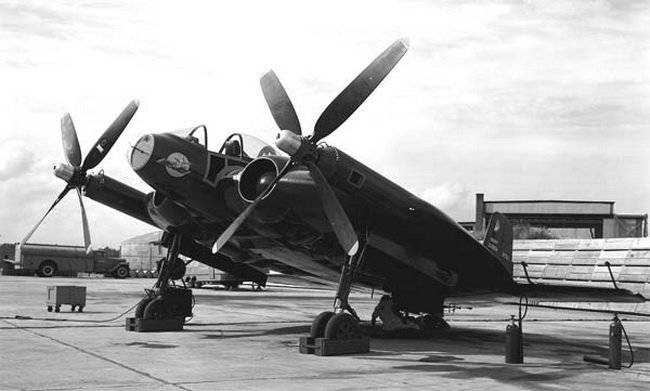
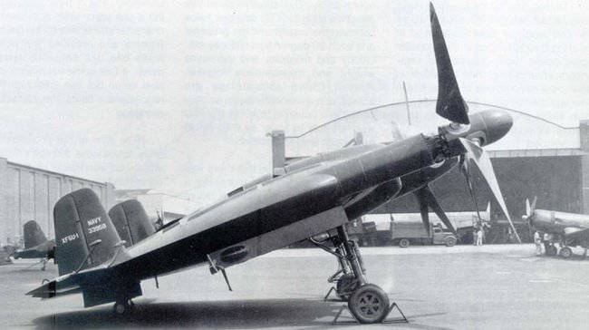
Unfortunately, from the creation of the first prototype of the XF5U-1 fighter, which was removed from the hangar on 25 on June 1945 of the year, too much time passed before the first flight in mid-January of 1947. Skimmer, as the XF5U-1 fighter in the company was nicknamed, completed the flight test program with honor and even set the speed record of those years, showing a speed of 811 km / h. This unofficial record for flight speed belonged to Richard Burovso, who reached it at the afterburner at an altitude of 8808 meters. In addition, the aircraft demonstrated the possibility of vertical take-off with a special trapezoid. The plane took off in a helicopter with screws raised up, as well as any helicopter, it could hover in the air.
However, despite the uniqueness of the development, the project for the XF5U-1 fighter was closed. The main reasons for this decision turned out to be two: financial difficulties at the company, and the rejection of the Skimmer project was the easiest way to save, and the fact that aviation The United States began to rearm on jet technology. According to the instructions of the Navy in the spring of 1948, all valuable equipment was removed from the aircraft, after which their hulls were crushed by bulldozers into scrap metal. At the same time, the prototype V-173 was transferred to the museum at the Smithsonian Institute, where it is safely stored to this day.
Description of construction
The XF5U-1 fighter in its external form practically repeated the V-173 and was a two-kile monoplane with an integral layout and an elliptical wing of the NACA 0015 symmetric profile throughout its span. Structurally, the fighter consisted of 3-x main parts: front, middle and rear. In front of the pilot's cockpit, compartments with small arms and air intakes with fans forced cooling engines. The middle part of the fuselage of the fighter was formed by 2-mea power spar frames, between which were located the motors, shafts and gearboxes, the main and consumable fuel tanks, screw drives. At the bottom of the front power frame mounted main landing gear. At the rear of the fighter fuselage housed the tail wheel, the main controls of the machine, as well as the brake hook.
The XF5U-1 power kit was made from aluminum alloys, while the aircraft skin was made from a new composite material called metalite, which was patented by Vought and was a sandwich glued and formed in a rather large autoclave of 2 thin aluminum sandwich sheets, which were separated by a layer of ultralight wood - balsa. The rigidity and durability of the material used for the plating has allowed a drastic reduction in the number of ribs and frames supporting the plating, turning the structure into almost monocoque.
The cockpit was sealed and had a closed drop-shaped lantern, which was movable. The drive of his shift was electric. The seat of the fighter pilot was catapulted, using the JD-1 chair, manufactured by Martin-Baker, England. The main flight-navigation instruments, instruments for controlling the power plant and fighter systems were located on the front panel of the dashboard. On the left panel were the knobs for controlling the cyclic pitch of the screws, motor, trimmers, brake hook and chassis. The right panel was occupied by the control panel of the radio station and the gas station.
The power plant of the fighter included 2 fourteen-cylinder twin-row Pratt & Whitney R-2000-2 (D) engines with a capacity of 1600 hp each. On the front of the crankcase of each motor, a gearbox with bevel gears was fixed, which transmitted torque to a single transverse shaft of the propeller drive. In addition, an engine cooling fan was connected to the gearbox. On the lower and upper parts of the fuselage there were special flaps through which hot exhaust air exited. Exhaust gases were discharged under the body of the car through a special U-shaped exhaust pipe and manifold. In the event that one engine failed, the pilot could disconnect it from the gearbox using the correct clutch. The propeller blades were wooden, and the propellers themselves had a variable total and cyclic pitch.
The aircraft was equipped with a three-post landing gear with tail wheel, the cleaning system is hydraulic. All landing gear fighter were two-wheeled. The large parking angle of the car made the designers place a brake hook on the upper surface of the fuselage. The control system of the fighter was mechanical, rigid. In pitch and roll, it was controlled using differential deflectable all-turn stabilizers. Stabilizers were equipped with external weight compensators and trimmers. Stabilization of the fighter in the direction was made at the expense of 2-x trapezoidal carinae with the rudders having a large area. In the tail of the aircraft were automatic flaps used during landing.
The prototypes of the XF5U-1 fighter did not mount weapons, but it was envisaged that production aircraft would be armed with six Browning machine guns (ammunition for 12,7 ammunition per barrel) or four 400-mm M-20 air guns. Also under the fuselage could be located 39 pylon for installing fuel tanks with a capacity of 2 a liter or two bombs with a total weight up to 568 kg. Dive bombing or the use of unguided rockets was completely eliminated due to the excessive diameter of the propellers.
Information sources:
-http: //warplanefuns.ru/planes-main/amerika-main/item/33-f5u.html
-http: //www.airwar.ru/enc/fighter/f5u.html
-http: //www.aviarmor.net/aww2/aircraft_exp/usa/Vought%20V-173.htm
History create
In 1933, the famous American aerodynamic scientist, Charles Zimmerman, carried out a series of experiments with a wing of small elongation. Conducted theoretical studies have demonstrated the effectiveness of this scheme. According to his idea, at the ends of the wing of ultra-low elongation there should have been screws that would be turned in the direction opposite to the direction of rotation of the air vortices descending from the wing. This made it possible to reduce the inductive resistance of the “wing-screws” system and build a machine with a large range of speeds. At the same time, the use of low-speed large-diameter propellers with sufficient power capacity would allow the machine to take a vertical take-off and hang in the air, like a cross-section helicopter, and low drag would increase the flight speed.
The first manned model of this scheme with a wingspan of 2 meter Zimerman built in 1935 year. The model was equipped with two cleon air-cooled engines for 25 hp. This model was never able to get off the ground due to the inability to achieve synchronization of the rotation of the screws. After that, Zimmerman designed a new rubber-motor model with a wingspan of 0,5 meters. This model has successfully flown. After that, the designer achieved support at NASA, where before that his designs were rejected as too modern. In the summer of 1937, the designer was invited to work for Chance-Vout. Here, taking advantage of the great potential of laboratories, Charles Zimmerman was able to build a V-162 electrolyte with a wingspan of an 1 meter. This electrolyte successfully flew in the hangar.
The following year, the military was interested in Zimmerman’s development of 1938, and at the beginning of 1939, he took part in a competition to create an unconventional fighter. Works under this competition were funded by the US Navy. It was then that Zimmerman set about creating a light-V-173 aircraft. This aircraft had a rather complicated wooden structure, which was covered with fabric. The model was equipped with 2-I synchronized engines "Continental" A-80 horsepower 80. These motors rotated the 2 huge three-bladed propellers through a reducer, the diameter of which was 5,03 m. The wingspan of the aircraft was 7,11 meters, the wing area was 39,67 square meters. The total length of the aircraft was equal to 8,13. The aircraft’s landing gear was made non-retractable to facilitate construction. At the rate the aircraft was controlled with the help of 2-x fins with rudders, the pitch and roll of the machine was controlled with the help of all-turning Elevons.
Because of the revolutionary concept that was implemented in the V-173, it was decided to flush the aircraft in one of the largest wind tunnels in the world at that time, located in the Langley Field test facility. Tests in the pipe successfully ended in December 1941 year, after which the aircraft proceeded to flight tests. After conducting short runs at the company's airfield in Stratford, the chief pilot of Chans-Vout, Boone Gayton, lifted the car into the air. It happened this November 23 1942 of the year.
With take-off weight in 1400 kg. The power of two 80-strong engines was clearly not enough for the car. At the same time, as a result of engine failure, the V-173 made forced landings several times, and once on the sandy beach, even skapote. But each time the structural strength and low landing speed saved the aircraft from serious damage. In this case, the main drawback of the car, the test pilots called a bad view from the cockpit during taxiing and during takeoff. The reason for this was too large a parking angle in 22 degrees. The takeoff of the prototype V-173 was only 60 m., And if there was a head wind in 46 km / h, it could fly up vertically. The maximum speed was 222 km / h, the maximum ceiling - 1 524 m.
In parallel with this, work was going on to create a fighter, which had the corporate designation VS-315. By June 1942, the technical proposal for this aircraft was transferred to the Aeronautics Bureau. The new fighter, according to the naming system adopted by the US Navy, received the designation XF 5U-1. The main feature of this machine was the ratio between the landing and maximum flight speed - about 11, whereas for airplanes of the usual pattern was characterized by a value equal to 5. The fighter’s estimated speed range was from 32 to 740 km / h.
To achieve the stated characteristics of the machine, it was necessary to solve a number of problems. For example, at low flight speeds, the angle of attack greatly increased. Due to the asymmetry of the flow around on the prototype V-173, quite strong vibrations were noted that threatened the structural strength. In order to get rid of them, a mover was created, called the “unloaded propeller”. It was a wooden propeller of very complex shape. Blades of complex shape with a wide butt joined the steel lugs, which in turn were connected with a swashplate machine gun. With it, you can change the cyclic pitch of the propeller blades.
The Pratt-Whitney company took part in creating the propeller group for the new fighter, which designed and manufactured a synchronizer for the R-2000-7 engines, a clutch, five-time gearboxes that allowed any of the 2-x engines to shut down in case of overheating or damage. The specialists of this company also helped to design a fundamentally new fuel system, which allowed the engines to be supplied with fuel during long flights at high angles of attack (up to 90 degrees while hovering them in helicopter mode).
Unfortunately, from the creation of the first prototype of the XF5U-1 fighter, which was removed from the hangar on 25 on June 1945 of the year, too much time passed before the first flight in mid-January of 1947. Skimmer, as the XF5U-1 fighter in the company was nicknamed, completed the flight test program with honor and even set the speed record of those years, showing a speed of 811 km / h. This unofficial record for flight speed belonged to Richard Burovso, who reached it at the afterburner at an altitude of 8808 meters. In addition, the aircraft demonstrated the possibility of vertical take-off with a special trapezoid. The plane took off in a helicopter with screws raised up, as well as any helicopter, it could hover in the air.
However, despite the uniqueness of the development, the project for the XF5U-1 fighter was closed. The main reasons for this decision turned out to be two: financial difficulties at the company, and the rejection of the Skimmer project was the easiest way to save, and the fact that aviation The United States began to rearm on jet technology. According to the instructions of the Navy in the spring of 1948, all valuable equipment was removed from the aircraft, after which their hulls were crushed by bulldozers into scrap metal. At the same time, the prototype V-173 was transferred to the museum at the Smithsonian Institute, where it is safely stored to this day.
Description of construction
The XF5U-1 fighter in its external form practically repeated the V-173 and was a two-kile monoplane with an integral layout and an elliptical wing of the NACA 0015 symmetric profile throughout its span. Structurally, the fighter consisted of 3-x main parts: front, middle and rear. In front of the pilot's cockpit, compartments with small arms and air intakes with fans forced cooling engines. The middle part of the fuselage of the fighter was formed by 2-mea power spar frames, between which were located the motors, shafts and gearboxes, the main and consumable fuel tanks, screw drives. At the bottom of the front power frame mounted main landing gear. At the rear of the fighter fuselage housed the tail wheel, the main controls of the machine, as well as the brake hook.
The XF5U-1 power kit was made from aluminum alloys, while the aircraft skin was made from a new composite material called metalite, which was patented by Vought and was a sandwich glued and formed in a rather large autoclave of 2 thin aluminum sandwich sheets, which were separated by a layer of ultralight wood - balsa. The rigidity and durability of the material used for the plating has allowed a drastic reduction in the number of ribs and frames supporting the plating, turning the structure into almost monocoque.
The cockpit was sealed and had a closed drop-shaped lantern, which was movable. The drive of his shift was electric. The seat of the fighter pilot was catapulted, using the JD-1 chair, manufactured by Martin-Baker, England. The main flight-navigation instruments, instruments for controlling the power plant and fighter systems were located on the front panel of the dashboard. On the left panel were the knobs for controlling the cyclic pitch of the screws, motor, trimmers, brake hook and chassis. The right panel was occupied by the control panel of the radio station and the gas station.
The power plant of the fighter included 2 fourteen-cylinder twin-row Pratt & Whitney R-2000-2 (D) engines with a capacity of 1600 hp each. On the front of the crankcase of each motor, a gearbox with bevel gears was fixed, which transmitted torque to a single transverse shaft of the propeller drive. In addition, an engine cooling fan was connected to the gearbox. On the lower and upper parts of the fuselage there were special flaps through which hot exhaust air exited. Exhaust gases were discharged under the body of the car through a special U-shaped exhaust pipe and manifold. In the event that one engine failed, the pilot could disconnect it from the gearbox using the correct clutch. The propeller blades were wooden, and the propellers themselves had a variable total and cyclic pitch.
The aircraft was equipped with a three-post landing gear with tail wheel, the cleaning system is hydraulic. All landing gear fighter were two-wheeled. The large parking angle of the car made the designers place a brake hook on the upper surface of the fuselage. The control system of the fighter was mechanical, rigid. In pitch and roll, it was controlled using differential deflectable all-turn stabilizers. Stabilizers were equipped with external weight compensators and trimmers. Stabilization of the fighter in the direction was made at the expense of 2-x trapezoidal carinae with the rudders having a large area. In the tail of the aircraft were automatic flaps used during landing.
The prototypes of the XF5U-1 fighter did not mount weapons, but it was envisaged that production aircraft would be armed with six Browning machine guns (ammunition for 12,7 ammunition per barrel) or four 400-mm M-20 air guns. Also under the fuselage could be located 39 pylon for installing fuel tanks with a capacity of 2 a liter or two bombs with a total weight up to 568 kg. Dive bombing or the use of unguided rockets was completely eliminated due to the excessive diameter of the propellers.
Information sources:
-http: //warplanefuns.ru/planes-main/amerika-main/item/33-f5u.html
-http: //www.airwar.ru/enc/fighter/f5u.html
-http: //www.aviarmor.net/aww2/aircraft_exp/usa/Vought%20V-173.htm
Information