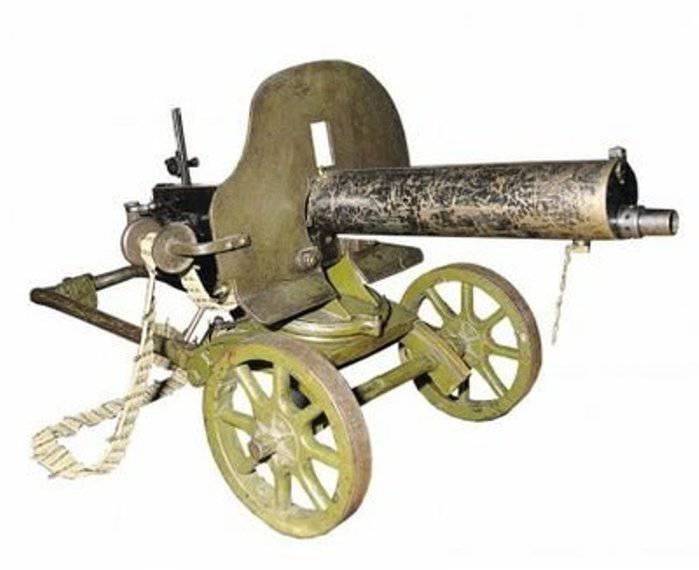
Machine gun "Maxim" model 1910 g.
The Maxim machine gun of the 1910 model of the year was a modernized version of the 1905 model machine gun of the year. Its mass production was carried out at the Imperial Tula Arms Plant (ITOZ) since May 1905 of the year under the license of the company “Maxim, Vikkers & Suns” (England). The main role in the refinement of the systems of both Maxim’s models and the production of machine guns belonged to the guard, Colonel Tretyakov, and the senior class master Pastukhov who served in the IHTO. The essence of the modernization, which was carried out in 1909 year, was to create a lighter machine gun. Some parts made of bronze (barrel cover, receiver, handles and others) were replaced with steel ones. The sight, the details of the casing and the box, the trigger thrust, the butt pad also changed. The first two machine guns upgraded by Tula gunsmiths were put to the test 15 June 1909 of the year (where they became competitors of the new Vickers machine gun). After the corresponding modifications, the Tula “lightened” machine gun was adopted by giving it the designation “Maxim machine gun of the 1910 model of the year” with a field wheeled machine of Colonel Sokolov. Serial production of the new Maxima and the machine began in 1911. The machine gun of the 1910 model of the year was indeed significantly improved compared to the prototype, primarily in terms of technology, but it is hardly correct to say that “Russian technicians had created, in fact, a new machine gun” established in Russian literature.
The machine gun consisted of: barrel; a frame which included a locking mechanism, a drum, a handle and a chain; a bolt (lock) with a percussion mechanism, a combat larva, lifting and locking levers; trigger release; a box (riveted) with a folding cover; butt pad with fuse, release lever and control knobs; return spring with casing (box); a receiver having a tape feed mechanism; barrel casing with a sleeve and steam tube, drain and filling holes; sights; muzzle.
In automatics the scheme of recoil of the trunk was implemented with a short course. Locking the barrel was carried out by a system consisting of two articulated levers. The connecting rod (front lever) was connected to the shutter by a flat hinge, and the bloodworm (rear lever) was also attached pivotally to the rear of the frame, that is, the frame was a receiver. At the right end of the axis of the moth was worn a swinging handle, on the left - an eccentric (drum) with a chain of Gall, which was connected with a return spring. The return spring was fastened in a separate box located on the left wall of the Maxim box. The castle was assembled drummer with a plate of two-wing combat spring. The combat larva, having clamps to hold the liner, slid vertically in the lock grooves, had a hole for the striker to pass, so the shot could be made only if the larva was in a certain position. Drummer cocked ankle. In this case, the upper safety descent captured him. Ankle her platoon got up on the lower slope.
The trigger lever, having a key under the finger, was placed between the control knobs, to hold the fuse. The canvas cartridge belt was inserted into the transverse window of the receiver on the right. Ribbon nests were divided by metal plates fastened with rivets. In this case, the rivets were put with a little tightness, one hundred allowed to firmly hold the cartridge in the socket. Cartridge box was installed separately from the machine gun. For reliable operation of the filing, the second number kept the tape in the correct position with its hands. The weight of the canvas ribbon was 1,1 kg. The cutout wall of the left frame of the barrel frame actuated the feed mechanism. On the first Maxim machine guns of the 1910 model of the year, a reel was installed on the box, which was intended to direct the canvas tape to the receiver. Later the coil was moved to the shield.
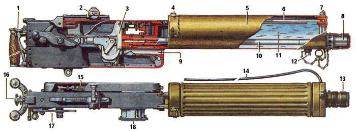 1 is a fuse, 2 is a sight, 3 is a lock, 4 is a filler plug, 5 is a casing, 6 is a steam dispenser, 7 is a fly, 8 is a muffler, 9 is a liner output tube, 10 is a barrel, 11 12 is 13, 15 is a sleeve, 16 is a sleeve, 17 is X-tube, 18 is XnUMX -stitchpipe pourer, XNUMX - cap, steam gut, XNUMX-return spring, XNUMX-trigger lever, XNUMX-handle, XNUMX-receiver.
The shot was made from the closed shutter. It was necessary to raise the fuse and pull the trigger. At the same time, the triggering trigger retracted, delaying the tail of the lower trigger, releasing the ankle. The striker passed through a hole in the larva, smashed the cartridge primer. The lock under the effect of recoil sought to retreat back, transferring pressure to the crank and crank. The crank and crank constituted an angle, the top of which was facing upward, and rested against the protrusions of the frame with its hinge. The barrel and frame with the lock moved back. After the moving system passed about 20 millimeters, the handle came up on the fixed roller of the box and went up turning the crank down. As a result, the leverage system was straightened, the lock was more pressed against the bore. Powder gases after the bullet had fallen hit the muzzle, pushing the front section of the barrel, the mobile system received an additional boost. The design of the Russian sample muzzle was developed by Zhukov and brought Shepherds. The barrel, moving back, opened the transverse holes in the muzzle, through which the excess powder gases were discharged. Turning, the handle caused the arms to be folded down and away from the barrel. At the same time, the handle was an accelerator of the lock, transferring to it the kinetic energy of recoil and braking the frame and trunk. The larva of the castle, holding the cartridge case behind the rim, removed it from the chamber. The tube of the locking levers, while lowering the connecting rod, pressed on the tail of the ankle, which, turning, cocked the drummer. With lifting levers a larva was raised, exciting the next cartridge from the receiver window (the window was longitudinal). During the further movement of the system, the back curved leaf springs located on the inside of the box lid lowered the larva. At the same time, the slider of the feed mechanism was retracted to the right by the crank lever. The fingers of the ram dropped into the next cartridge. Chain when turning the handle wound on the drum, stretching the return spring. The mass of the barrel was 2,105 kilogram, the moving system - 4,368 kilogram. The length of the barrel stroke back was equal to 26 millimeters, the lock relative to the barrel to 95 millimeters. The coordination of the movement of the lock and the trunk was achieved by regulating the tension of the return spring.
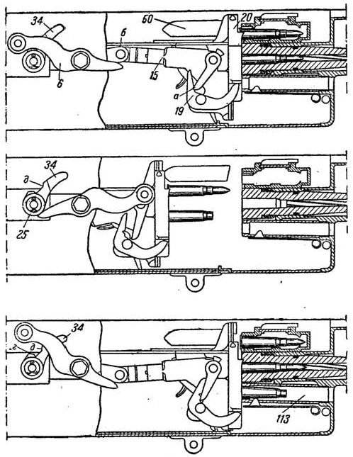
The handle at the end of the turn hit the roller with a short shoulder and began to reverse the turn (the early models of the Maxim machine gun had a separate spring for this). The movable system under the action of the return spring went forward. The lock was sent to the cartridge in the chamber, and the cartridge case was sent to the sleeve tube, from where it was pushed out during the next cycle. The crank lever shifted the slider to the left, and he pushed the next cartridge to the receiver window. During the turn of the bloodworm and the connecting rod, the tail of the safety lever was lifted by a tube of locking levers. When the battle larva got in front of the striker with its hole, the top trigger was released by the drummer, and if the trigger was pressed, a shot was made.
The machine gun consisted of 368 parts. The maximum gas pressure in the barrel left about 2850 kg / sq. Cm, and the average about 1276 kg / sq. Cm. During training, an idle shooting sleeve was used, which was screwed into the muzzle. In the event of a breakdown of the mainspring, debris was removed through the bottom of the box.
Machine gun "Maxim" model 1910, had a rack-mount sight, mounted on the lid of the box. At the front there was a sighting bar with divisions for pickup in range. On the transverse tube of the yoke were applied division, which was installed pillar. A fly of triangular section was inserted into the groove on the casing. The aiming line was 911 millimeters. The height of the fly over the axis of the barrel bore was equal to 102,5 millimeters, so the casing attachment accuracy had a great influence on the accuracy. The sight was set at a distance of up to 3,2 thousand steps (2270 meters), but the effective range did not exceed 1,5 thousand meters.
The casing capacity was about 4,5 liters. Some machine guns had casings with longitudinal fins, which increased rigidity and increased the cooling surface, but they declined from the fins in favor of simplifying production. Used in some armies, canvas or rubber hoses for the removal of steam into the atmosphere or into a canister-capacitor, in the Russian army were used only in armored installations.
With the help of a crank mechanism, smooth and almost unstressed operation of the automatics was ensured. The use of the drive of the power supply system from the frame was rational in terms of the uniform distribution of recoil energy. Maxim's system had a high survivability and reliability, which ensured its exceptional longevity. Although the external position of the grip posed a danger to the calculation, it made it easier to assess the condition, as well as identify and eliminate the delay in firing. The production of a machine gun was quite complex and required not only high-quality steel and skilled workers, but also numerous special equipment. The assembly and initial run-in of the nodes also required some fixtures.
The Sokolov machine, which he developed with the participation of Platonov the master of the St. Petersburg gun factory, consisted of a skeleton with a trunk, wheel and table. The rim and spokes of the wheels were made of oak, the tire was made of steel, the nuts and bushings were made of bronze. The table itself carried a clamp-type swivel having a clamp, precise and coarse vertical guidance mechanisms, as well as a shield. The machine gun was attached to the swivel for the front eyes of the box. The lower eye connected the machine gun and the head of the lifting mechanism. Rough vertical guidance was made by moving the table along the arcs of the core. In the first version of the machine, there were two folding legs, a seat, and a roller at the end of the trunk on the skeleton. This design allowed to fire from two positions and roll the machine gun by the strap. While carrying the legs folded back, and the trunk - forward. Later, the front legs, the roller and the seat were removed, and the small opener was strengthened at the end of the trunk. These changes led to the fact that the maximum angle of elevation decreased to 18 degrees (from 27), and the declination - to 19 degrees (from 56), shooting was carried out only from a prone position. The mass of the 6,5-mm shield with the size of 505x400 of millimeters was 8,0 kilogram (with the coil of the guide tape - 8,8 kilogram). It was believed that the shield would protect the machine-gun crew from rifle bullets at a distance over 50 meters. Although the convenience of the wheel machine, even on a slightly rugged terrain, is doubtful, in our country the addiction to them lasted a long time.
Until the complete “victory” of Sokolov’s machines in Russia with the Maxim machine gun, several installations were used. The field and serf wheeled carriages before the 1914 were re-armed, but the Vickers tripods of the 1904, 1909 and 1910 samples remained.
The Vickers tripod of the 1904 model of the year had a mass of 21 kilogram, the height of the line of fire - 710 millimeters, the angle of vertical guidance - from - 20 to + 15 degrees, horizontal guidance - 45 degrees, its modification of the 1909 model of the year has a new lifting mechanism that had 32 kilogram weight , vertical pointing angle - from 15 to + 16 degrees, horizontal pointing - 52 degrees. The 1910 model tripod had a weight of 39 kilogram, shield weight 534x400 millimeters - 7,4 kilogram, vertical pickup angle - from -25 to + 20 degrees, horizontal - 52 degrees, in position held three fixed positions.
In 1915, the machine gun “Maxim” adopted a simpler to produce and easier machine Kolesnikov system. This machine was manufactured by the Petrograd Artillery Plant, the Kiev, Bryansk and Petrograd arsenals. The release of shields engaged in Izhevsk and Sormovsky plants. Kolesnikov had a tubular boom with a coulter and rope loops instead of handles, 305 millimeter oak wheels with steel tires and hubs and bronze bushings, horizontal and vertical guidance mechanisms, a shield mount. The disadvantage of the design was that the axis of the bore axis was too high relative to the axles of the wheel travel and the vertical guidance mechanism. This increased dispersion during shooting. The weight of the machine was equal to 30,7 kilograms, 7 millimeter shield size 498x388 millimeters - 8,2 kilogram, vertical guidance angle - from -25 to + 32 degrees, horizontal - 80 degrees. The machine consisted of 166 parts, including knitting needles. During the war, the machine gun and the machine were painted in a protective color.

To save money during training machine gunners instead of live ammunition used manufactured cartridges having a reduced powder charge. A box with live ammunition destined for machine guns was marked with the letter “P” before being sent to the troops.
From foreign companies and domestic inventors have received a large number of proposals regarding sights, as well as devices for dictating "hidden" firing from a machine gun. The latter was a periscopic sight mounted on a parapet of a trench and an additional trigger lever. Such sights were tested, but more than one sample was not adopted.
The urgent problem of firing at air targets gave rise to many different versions of improvised anti-aircraft installations in the military. For example, the Sokolov machine developed a rack with a clip for anti-aircraft firing. In the autumn of 1915, the master Kolesnikov produced a tripod "machine-gun machine for firing at airborne vehicles." Conscious in the workshops of the Shooting Range, the machine gave large elevation angles and circular fire, the aiming was free, a clamp was used to fire “to the point”, the butt could be mounted. Titular adviser Fedorov was presented anti-aircraft installation, easily made from scrap materials. The machine gun on it was set with a Sokolov machine. Such a setup allowed firing at angles of vertical guidance from + 30 to + 90 degrees. 5-th Department of Artcom decided to send descriptions of these installations to the troops, transferring from the "preparation" at its own discretion. Established anti-aircraft machine gun in the Russian army and did not pass.
Lieutenant General Kabakov, an inspector of the rifle unit in the army, on October 11, 1913, in a note to the Aeronautical Unit of the GUGSH, gave recommendations for remaking machine guns "Maxim" in aviation - although these recommendations were not implemented, however, after five years, the Germans made similar changes to the MG.08 / 18 machine gun.
The procedure for unloading the Maxim machine gun of the 1910 model of the year: Press the fingers from the bottom of the receiver tray on the right side to remove the tape. Twice back, and then release the cocking handle located on the right side of the box. Using a pencil or other object suitable for this purpose, make sure that there is no cartridge or cartridge case in the under-barrel front tube. Raise the fuse to press the trigger.
Partial disassembly of the Maxim machine gun of the model 1910 of the year with a Sokolov machine:
1. Before disassembling, pour coolant out of the housing. Separate the shield from the machine. For this purpose: the nut of the connecting bolt is loosened; the bolt head tail turns up to a horizontal position; The shield is removed up.
2. The cover of the box opens, giving the fastener a thumbs forward.
3. Removing the lock. To do this: send the handle forward with your right hand to failure; the left hand takes the back of the castle and lifts a little upwards; smoothly lowering the handle, the lock is raised from the box; the lock is rotated and removed from the connecting rod.
4. Drummer descends to release the mainspring. For this it is necessary: while holding the combat larva in the highest position, press the tube of the lock levers to the platform; free the drummer from the upper descent; pressing the tail of the lower descent gently pull the drummer.
5. The receiver is taken with both hands and taken out upwards.
6. Separated spring return box. To do this, the box is fed forward so that the hooks come off the box spikes, after which the drum chain is removed from the hook of the return spring.
7. The back plate is extended. To do this, squeeze the head of the split checks with your fingers pulling it to the side; push the pad back up with both hands on its handles (if it is difficult to extend the pad, you can use a special lever device).
8. Fold the handle forward, holding the roller and the valve, push the right valve to the right, sweeping the left valve on both sides behind it.
9. The frame with a trunk is taken. For this: the crank will rise and fall on the bloodworm; grab the handle with your right hand, fixing it (do not allow to turn), hold the drum with your left hand, push the frame back; to clasp the trunk and the extended end of the left bed with your left hand; remove from the box frame with a barrel.
10. The barrel is separated from the frame. To do this: clasping the end of the left frame and the trunk with the left hand; after that the left bed is removed.
11. Removed trigger release. For this purpose, the thrust is supplied to itself, rises upwards beyond the end and is removed from the box.
12. The cap is removed from the muzzle by turning it to the right; the sleeve is unscrewed from the muzzle using two keys; screwdriver unscrews the muzzle.
Machine gun assembly order:
1. In the box is embedded traction. Its hole is put on the spike in the bottom of the duct, while the thorn of the thrust is inserted into the hole in the bottom of the duct; traction goes all the way forward.
2. The trunk and frame are connected: take the trunk with the rear oil seal wound on it in the left hand (the number should be turned up) and put the frame beds on the trunnion of the trunk - the left and then the right.
3. Attach the barrel and frame: put the crank on the crank; Carefully slide the barrel into the casing, and the frame into the box.
4. Raise the handle to insert the right valve; move left.
5. Insert the back plate. To do this, hold the back plate by the handles and slide it onto the box strips in the grooves. In this case, it is necessary that the thrust be in the forward extreme position. On the right side insert a check.
6. Attach a box having a return spring. For this it is necessary to put a tension tension screw vertically; put the handle in place and put a drum chain on the spring hook (spring is circled below); hold the machine gun, feed the box forward and put the box hooks on the box spikes.
7. Insert the receiver. For this purpose, the receiver is inserted into the upper notches of the box in slots; the slider should be in the left position.
8. Screw in the muzzle. Wind the front oil seal on the muzzle end of the barrel, screw the sleeve into the muzzle, insert the muzzle into the hole of the casing, and then screw the muzzle.
9. Put in the box lock. To do this, the connecting rod is raised, and the drummer is cocked to a combat platoon. After that, holding the lock with the horns forward and the battle larva up, put the tube of the lock levers on the connecting rod to the stop, turn the lock and insert it into the box; hold the lock, send the handle forward and release it. The lock should go into the grooves of the ribs of the frame with its platform.
10. Close the box cover.
11. Raise the fuse, pull the trigger.
12. Put the cap on the muzzle.
Technical characteristics of the Maxim machine gun of the model 1905 of the year
Cartridge - 7,62-mm sample 1891 of the year (7,62x53);
The mass of the "body" of the machine gun (without coolant) - 28,25 kg;
The length of the "body" of the machine gun - 1086 mm;
Barrel length - 720 mm;
Initial bullet speed - 617 m / s;
Aim range - 2000 steps (1422 m);
Firing Rate - 500-600 shots / min;
Combat rate of fire - 250-300 after suffering / min;
Tape capacity - 250 cartridges.
Technical characteristics of the Maxim machine gun of the model 1910 of the year:
Cartridge - 62-mm sample 1908 of the year (7,62x53);
The mass of the "body" of the machine gun (without coolant) - 18,43 kg;
The length of the "body" of the machine gun - 1067 mm;
Barrel length - 720 mm;
Initial bullet speed - 665 m / s;
Grooves - 4 right;
The length of the stroke rifling - 240 mm;
Initial bullet speed - 865 m / s;
Aim range - 3200 steps (2270 m);
The longest firing range - 3900 m;
The maximum range of the bullet - 5000 m;
Direct shot range - 390 m;
Rate of fire - 600 shots / min;
Combat rate - 250-300 shots / min;
Tape capacity - 250 cartridges;
Weight curb tape - 7,29 kg;
Belt length - 6060 mm.
Specifications machine Sokolov:
Weight with shield - 43,5 kg;
The angle of vertical guidance is from -19 to + 18 degrees;
The angle of horizontal guidance - 70 degrees;
The height of the line of fire is about 500 mm;
The greatest length of the machine gun with a machine - 1350 mm;
Stroke width - 505 mm;
The distance from the center of gravity to the opener is 745 mm.
Based on: S. Fedoseev - Machine Guns in the First World War
The machine gun consisted of: barrel; a frame which included a locking mechanism, a drum, a handle and a chain; a bolt (lock) with a percussion mechanism, a combat larva, lifting and locking levers; trigger release; a box (riveted) with a folding cover; butt pad with fuse, release lever and control knobs; return spring with casing (box); a receiver having a tape feed mechanism; barrel casing with a sleeve and steam tube, drain and filling holes; sights; muzzle.
In automatics the scheme of recoil of the trunk was implemented with a short course. Locking the barrel was carried out by a system consisting of two articulated levers. The connecting rod (front lever) was connected to the shutter by a flat hinge, and the bloodworm (rear lever) was also attached pivotally to the rear of the frame, that is, the frame was a receiver. At the right end of the axis of the moth was worn a swinging handle, on the left - an eccentric (drum) with a chain of Gall, which was connected with a return spring. The return spring was fastened in a separate box located on the left wall of the Maxim box. The castle was assembled drummer with a plate of two-wing combat spring. The combat larva, having clamps to hold the liner, slid vertically in the lock grooves, had a hole for the striker to pass, so the shot could be made only if the larva was in a certain position. Drummer cocked ankle. In this case, the upper safety descent captured him. Ankle her platoon got up on the lower slope.
The trigger lever, having a key under the finger, was placed between the control knobs, to hold the fuse. The canvas cartridge belt was inserted into the transverse window of the receiver on the right. Ribbon nests were divided by metal plates fastened with rivets. In this case, the rivets were put with a little tightness, one hundred allowed to firmly hold the cartridge in the socket. Cartridge box was installed separately from the machine gun. For reliable operation of the filing, the second number kept the tape in the correct position with its hands. The weight of the canvas ribbon was 1,1 kg. The cutout wall of the left frame of the barrel frame actuated the feed mechanism. On the first Maxim machine guns of the 1910 model of the year, a reel was installed on the box, which was intended to direct the canvas tape to the receiver. Later the coil was moved to the shield.
The shot was made from the closed shutter. It was necessary to raise the fuse and pull the trigger. At the same time, the triggering trigger retracted, delaying the tail of the lower trigger, releasing the ankle. The striker passed through a hole in the larva, smashed the cartridge primer. The lock under the effect of recoil sought to retreat back, transferring pressure to the crank and crank. The crank and crank constituted an angle, the top of which was facing upward, and rested against the protrusions of the frame with its hinge. The barrel and frame with the lock moved back. After the moving system passed about 20 millimeters, the handle came up on the fixed roller of the box and went up turning the crank down. As a result, the leverage system was straightened, the lock was more pressed against the bore. Powder gases after the bullet had fallen hit the muzzle, pushing the front section of the barrel, the mobile system received an additional boost. The design of the Russian sample muzzle was developed by Zhukov and brought Shepherds. The barrel, moving back, opened the transverse holes in the muzzle, through which the excess powder gases were discharged. Turning, the handle caused the arms to be folded down and away from the barrel. At the same time, the handle was an accelerator of the lock, transferring to it the kinetic energy of recoil and braking the frame and trunk. The larva of the castle, holding the cartridge case behind the rim, removed it from the chamber. The tube of the locking levers, while lowering the connecting rod, pressed on the tail of the ankle, which, turning, cocked the drummer. With lifting levers a larva was raised, exciting the next cartridge from the receiver window (the window was longitudinal). During the further movement of the system, the back curved leaf springs located on the inside of the box lid lowered the larva. At the same time, the slider of the feed mechanism was retracted to the right by the crank lever. The fingers of the ram dropped into the next cartridge. Chain when turning the handle wound on the drum, stretching the return spring. The mass of the barrel was 2,105 kilogram, the moving system - 4,368 kilogram. The length of the barrel stroke back was equal to 26 millimeters, the lock relative to the barrel to 95 millimeters. The coordination of the movement of the lock and the trunk was achieved by regulating the tension of the return spring.
The operation of the automatic system of the Maxim machine gun
The handle at the end of the turn hit the roller with a short shoulder and began to reverse the turn (the early models of the Maxim machine gun had a separate spring for this). The movable system under the action of the return spring went forward. The lock was sent to the cartridge in the chamber, and the cartridge case was sent to the sleeve tube, from where it was pushed out during the next cycle. The crank lever shifted the slider to the left, and he pushed the next cartridge to the receiver window. During the turn of the bloodworm and the connecting rod, the tail of the safety lever was lifted by a tube of locking levers. When the battle larva got in front of the striker with its hole, the top trigger was released by the drummer, and if the trigger was pressed, a shot was made.
The machine gun consisted of 368 parts. The maximum gas pressure in the barrel left about 2850 kg / sq. Cm, and the average about 1276 kg / sq. Cm. During training, an idle shooting sleeve was used, which was screwed into the muzzle. In the event of a breakdown of the mainspring, debris was removed through the bottom of the box.
Machine gun "Maxim" model 1910, had a rack-mount sight, mounted on the lid of the box. At the front there was a sighting bar with divisions for pickup in range. On the transverse tube of the yoke were applied division, which was installed pillar. A fly of triangular section was inserted into the groove on the casing. The aiming line was 911 millimeters. The height of the fly over the axis of the barrel bore was equal to 102,5 millimeters, so the casing attachment accuracy had a great influence on the accuracy. The sight was set at a distance of up to 3,2 thousand steps (2270 meters), but the effective range did not exceed 1,5 thousand meters.
The casing capacity was about 4,5 liters. Some machine guns had casings with longitudinal fins, which increased rigidity and increased the cooling surface, but they declined from the fins in favor of simplifying production. Used in some armies, canvas or rubber hoses for the removal of steam into the atmosphere or into a canister-capacitor, in the Russian army were used only in armored installations.
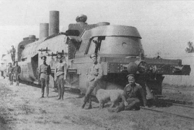
Machine guns heavily armed armored train. Russian armored train of the "Hunghus" type in Galicia, 1916. For arming such armored trains, they used both the Maxim machine guns and the captured Schwarzlose
With the help of a crank mechanism, smooth and almost unstressed operation of the automatics was ensured. The use of the drive of the power supply system from the frame was rational in terms of the uniform distribution of recoil energy. Maxim's system had a high survivability and reliability, which ensured its exceptional longevity. Although the external position of the grip posed a danger to the calculation, it made it easier to assess the condition, as well as identify and eliminate the delay in firing. The production of a machine gun was quite complex and required not only high-quality steel and skilled workers, but also numerous special equipment. The assembly and initial run-in of the nodes also required some fixtures.
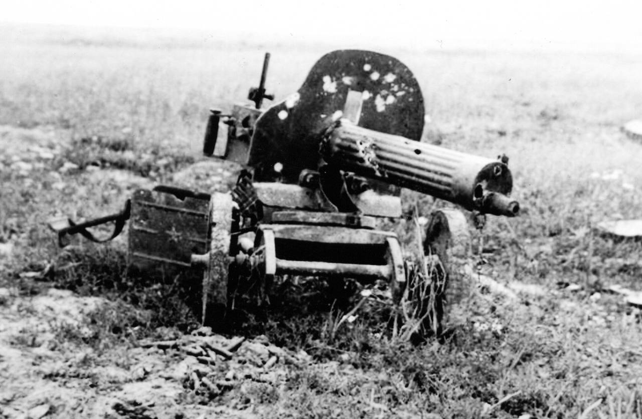
The Sokolov machine, which he developed with the participation of Platonov the master of the St. Petersburg gun factory, consisted of a skeleton with a trunk, wheel and table. The rim and spokes of the wheels were made of oak, the tire was made of steel, the nuts and bushings were made of bronze. The table itself carried a clamp-type swivel having a clamp, precise and coarse vertical guidance mechanisms, as well as a shield. The machine gun was attached to the swivel for the front eyes of the box. The lower eye connected the machine gun and the head of the lifting mechanism. Rough vertical guidance was made by moving the table along the arcs of the core. In the first version of the machine, there were two folding legs, a seat, and a roller at the end of the trunk on the skeleton. This design allowed to fire from two positions and roll the machine gun by the strap. While carrying the legs folded back, and the trunk - forward. Later, the front legs, the roller and the seat were removed, and the small opener was strengthened at the end of the trunk. These changes led to the fact that the maximum angle of elevation decreased to 18 degrees (from 27), and the declination - to 19 degrees (from 56), shooting was carried out only from a prone position. The mass of the 6,5-mm shield with the size of 505x400 of millimeters was 8,0 kilogram (with the coil of the guide tape - 8,8 kilogram). It was believed that the shield would protect the machine-gun crew from rifle bullets at a distance over 50 meters. Although the convenience of the wheel machine, even on a slightly rugged terrain, is doubtful, in our country the addiction to them lasted a long time.

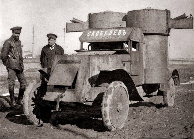
Installation of Maxim machine guns in the towers of the Austin armored car built by the Putilov factory
Until the complete “victory” of Sokolov’s machines in Russia with the Maxim machine gun, several installations were used. The field and serf wheeled carriages before the 1914 were re-armed, but the Vickers tripods of the 1904, 1909 and 1910 samples remained.
The Vickers tripod of the 1904 model of the year had a mass of 21 kilogram, the height of the line of fire - 710 millimeters, the angle of vertical guidance - from - 20 to + 15 degrees, horizontal guidance - 45 degrees, its modification of the 1909 model of the year has a new lifting mechanism that had 32 kilogram weight , vertical pointing angle - from 15 to + 16 degrees, horizontal pointing - 52 degrees. The 1910 model tripod had a weight of 39 kilogram, shield weight 534x400 millimeters - 7,4 kilogram, vertical pickup angle - from -25 to + 20 degrees, horizontal - 52 degrees, in position held three fixed positions.
In 1915, the machine gun “Maxim” adopted a simpler to produce and easier machine Kolesnikov system. This machine was manufactured by the Petrograd Artillery Plant, the Kiev, Bryansk and Petrograd arsenals. The release of shields engaged in Izhevsk and Sormovsky plants. Kolesnikov had a tubular boom with a coulter and rope loops instead of handles, 305 millimeter oak wheels with steel tires and hubs and bronze bushings, horizontal and vertical guidance mechanisms, a shield mount. The disadvantage of the design was that the axis of the bore axis was too high relative to the axles of the wheel travel and the vertical guidance mechanism. This increased dispersion during shooting. The weight of the machine was equal to 30,7 kilograms, 7 millimeter shield size 498x388 millimeters - 8,2 kilogram, vertical guidance angle - from -25 to + 32 degrees, horizontal - 80 degrees. The machine consisted of 166 parts, including knitting needles. During the war, the machine gun and the machine were painted in a protective color.
To save money during training machine gunners instead of live ammunition used manufactured cartridges having a reduced powder charge. A box with live ammunition destined for machine guns was marked with the letter “P” before being sent to the troops.
From foreign companies and domestic inventors have received a large number of proposals regarding sights, as well as devices for dictating "hidden" firing from a machine gun. The latter was a periscopic sight mounted on a parapet of a trench and an additional trigger lever. Such sights were tested, but more than one sample was not adopted.
The urgent problem of firing at air targets gave rise to many different versions of improvised anti-aircraft installations in the military. For example, the Sokolov machine developed a rack with a clip for anti-aircraft firing. In the autumn of 1915, the master Kolesnikov produced a tripod "machine-gun machine for firing at airborne vehicles." Conscious in the workshops of the Shooting Range, the machine gave large elevation angles and circular fire, the aiming was free, a clamp was used to fire “to the point”, the butt could be mounted. Titular adviser Fedorov was presented anti-aircraft installation, easily made from scrap materials. The machine gun on it was set with a Sokolov machine. Such a setup allowed firing at angles of vertical guidance from + 30 to + 90 degrees. 5-th Department of Artcom decided to send descriptions of these installations to the troops, transferring from the "preparation" at its own discretion. Established anti-aircraft machine gun in the Russian army and did not pass.
Lieutenant General Kabakov, an inspector of the rifle unit in the army, on October 11, 1913, in a note to the Aeronautical Unit of the GUGSH, gave recommendations for remaking machine guns "Maxim" in aviation - although these recommendations were not implemented, however, after five years, the Germans made similar changes to the MG.08 / 18 machine gun.
© RIA News, Infographics
The procedure for unloading the Maxim machine gun of the 1910 model of the year: Press the fingers from the bottom of the receiver tray on the right side to remove the tape. Twice back, and then release the cocking handle located on the right side of the box. Using a pencil or other object suitable for this purpose, make sure that there is no cartridge or cartridge case in the under-barrel front tube. Raise the fuse to press the trigger.
Partial disassembly of the Maxim machine gun of the model 1910 of the year with a Sokolov machine:
1. Before disassembling, pour coolant out of the housing. Separate the shield from the machine. For this purpose: the nut of the connecting bolt is loosened; the bolt head tail turns up to a horizontal position; The shield is removed up.
2. The cover of the box opens, giving the fastener a thumbs forward.
3. Removing the lock. To do this: send the handle forward with your right hand to failure; the left hand takes the back of the castle and lifts a little upwards; smoothly lowering the handle, the lock is raised from the box; the lock is rotated and removed from the connecting rod.
4. Drummer descends to release the mainspring. For this it is necessary: while holding the combat larva in the highest position, press the tube of the lock levers to the platform; free the drummer from the upper descent; pressing the tail of the lower descent gently pull the drummer.
5. The receiver is taken with both hands and taken out upwards.
6. Separated spring return box. To do this, the box is fed forward so that the hooks come off the box spikes, after which the drum chain is removed from the hook of the return spring.
7. The back plate is extended. To do this, squeeze the head of the split checks with your fingers pulling it to the side; push the pad back up with both hands on its handles (if it is difficult to extend the pad, you can use a special lever device).
8. Fold the handle forward, holding the roller and the valve, push the right valve to the right, sweeping the left valve on both sides behind it.
9. The frame with a trunk is taken. For this: the crank will rise and fall on the bloodworm; grab the handle with your right hand, fixing it (do not allow to turn), hold the drum with your left hand, push the frame back; to clasp the trunk and the extended end of the left bed with your left hand; remove from the box frame with a barrel.
10. The barrel is separated from the frame. To do this: clasping the end of the left frame and the trunk with the left hand; after that the left bed is removed.
11. Removed trigger release. For this purpose, the thrust is supplied to itself, rises upwards beyond the end and is removed from the box.
12. The cap is removed from the muzzle by turning it to the right; the sleeve is unscrewed from the muzzle using two keys; screwdriver unscrews the muzzle.
Machine gun assembly order:
1. In the box is embedded traction. Its hole is put on the spike in the bottom of the duct, while the thorn of the thrust is inserted into the hole in the bottom of the duct; traction goes all the way forward.
2. The trunk and frame are connected: take the trunk with the rear oil seal wound on it in the left hand (the number should be turned up) and put the frame beds on the trunnion of the trunk - the left and then the right.
3. Attach the barrel and frame: put the crank on the crank; Carefully slide the barrel into the casing, and the frame into the box.
4. Raise the handle to insert the right valve; move left.
5. Insert the back plate. To do this, hold the back plate by the handles and slide it onto the box strips in the grooves. In this case, it is necessary that the thrust be in the forward extreme position. On the right side insert a check.
6. Attach a box having a return spring. For this it is necessary to put a tension tension screw vertically; put the handle in place and put a drum chain on the spring hook (spring is circled below); hold the machine gun, feed the box forward and put the box hooks on the box spikes.
7. Insert the receiver. For this purpose, the receiver is inserted into the upper notches of the box in slots; the slider should be in the left position.
8. Screw in the muzzle. Wind the front oil seal on the muzzle end of the barrel, screw the sleeve into the muzzle, insert the muzzle into the hole of the casing, and then screw the muzzle.
9. Put in the box lock. To do this, the connecting rod is raised, and the drummer is cocked to a combat platoon. After that, holding the lock with the horns forward and the battle larva up, put the tube of the lock levers on the connecting rod to the stop, turn the lock and insert it into the box; hold the lock, send the handle forward and release it. The lock should go into the grooves of the ribs of the frame with its platform.
10. Close the box cover.
11. Raise the fuse, pull the trigger.
12. Put the cap on the muzzle.
Technical characteristics of the Maxim machine gun of the model 1905 of the year
Cartridge - 7,62-mm sample 1891 of the year (7,62x53);
The mass of the "body" of the machine gun (without coolant) - 28,25 kg;
The length of the "body" of the machine gun - 1086 mm;
Barrel length - 720 mm;
Initial bullet speed - 617 m / s;
Aim range - 2000 steps (1422 m);
Firing Rate - 500-600 shots / min;
Combat rate of fire - 250-300 after suffering / min;
Tape capacity - 250 cartridges.
Technical characteristics of the Maxim machine gun of the model 1910 of the year:
Cartridge - 62-mm sample 1908 of the year (7,62x53);
The mass of the "body" of the machine gun (without coolant) - 18,43 kg;
The length of the "body" of the machine gun - 1067 mm;
Barrel length - 720 mm;
Initial bullet speed - 665 m / s;
Grooves - 4 right;
The length of the stroke rifling - 240 mm;
Initial bullet speed - 865 m / s;
Aim range - 3200 steps (2270 m);
The longest firing range - 3900 m;
The maximum range of the bullet - 5000 m;
Direct shot range - 390 m;
Rate of fire - 600 shots / min;
Combat rate - 250-300 shots / min;
Tape capacity - 250 cartridges;
Weight curb tape - 7,29 kg;
Belt length - 6060 mm.
Specifications machine Sokolov:
Weight with shield - 43,5 kg;
The angle of vertical guidance is from -19 to + 18 degrees;
The angle of horizontal guidance - 70 degrees;
The height of the line of fire is about 500 mm;
The greatest length of the machine gun with a machine - 1350 mm;
Stroke width - 505 mm;
The distance from the center of gravity to the opener is 745 mm.
Based on: S. Fedoseev - Machine Guns in the First World War
Information