Experimental aircraft Convair XFY-1 Pogo (USA)
During development aviation technicians often proposed bold and unusual ideas, implying a rejection of the usual aircraft circuits. In the early fifties, attempts to create technology with vertical take-off and landing led to the appearance of Tailsitter-class aircraft. It was planned to test the unusual ideas underlying this concept with the help of two pilot projects from Lockheed and Convair. The latter introduced the Convair XFY-1 Pogo aircraft for testing.
The idea of an aircraft of the type Tailsitter ("Sitting on the tail") emerged from the analysis of the experience of using carrier-based aircraft and a number of new studies. With all its advantages, carrier-based fighters and bombers needed a large aircraft carrier ship and, by definition, could not work without it. At the end of the forties, an original idea was proposed that allowed a fighter to be placed on almost any ship or vessel. It was proposed to develop and build a vertical take-off combat aircraft.

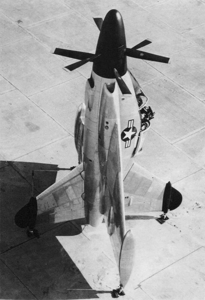
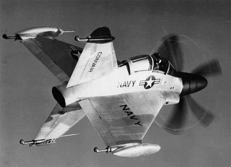
Prototype Convair XFY-1 during testing. Photo 456fis.org
According to the idea of the authors of the new concept, on the ground or on the deck of the carrier ship, the prospective "tailsitter" was to be placed vertically. This allowed him to take off without a takeoff run, and then go to the horizontal flight "in an airplane". Before landing, accordingly, it was necessary to return to vertical flight again. Without the need for a large runway or flight deck, such an aircraft could be based on a variety of ships with sufficient free space. As a result, he was of great interest to the naval forces.
The program to create a promising combat "tailsitter" started in 1948 year. At its first stages, research organizations were engaged in theoretical calculations and experiments, the results of which soon allowed to start creating full-fledged projects. The development of new technology was assigned to two leading aircraft manufacturers - Lockheed and Convair. They had a lot of experience in the creation of aircraft technology, including unusual schemes. Together with the experience of contractors, the companies should have used the data collected in recent studies.
Scheme of the car. Figure Airwar.ru
Initially, contracting companies were faced with a rather difficult task. They had to develop aircraft tailsters suitable for practical use in the armed forces. Then the command of the Navy was going to compare the two samples obtained and select the most successful one. This car was planned to be put into a series and sent to the troops. However, it soon became clear that such an approach to the creation of new military equipment would not be possible to put into practice. At first, it was necessary to test new original ideas during the tests, evaluate their prospects, and only after that take up the creation of a complete combat vehicle.
In this regard, in 1950, Lockheed and Convair received a new task. Now they were required to create experimental aircraft, with the help of which it would be possible to verify the concept of Tailsitter. With a favorable completion of this phase of the project it was possible to undertake the creation of combat aircraft.
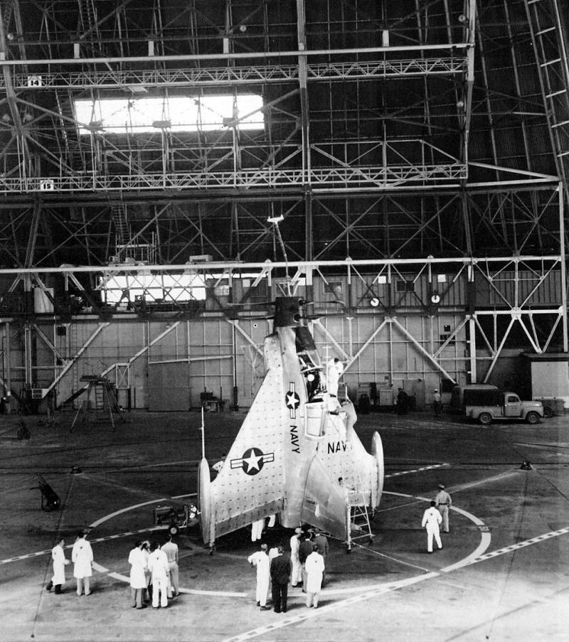
Preparation for tests in the hangar. Photo 456fis.org
On April 19, 1951, the U.S. Navy signed contracts for the construction of prototypes. In accordance with the agreement, Convair was to build and submit for testing two prototypes. Subsequently, the company proactively decided to build three cars that were to take on different types of tests. The Convair project at this stage received the official designation XFY-1, formed in accordance with the rules for the name of aircraft fleet. The first letter of the designation indicated the experimental nature of the project, the letter “F” assigned the aircraft to fighter aircraft, and the letter “Y” denoted Convair. The unit, respectively, showed that it was the first project in its lineup.
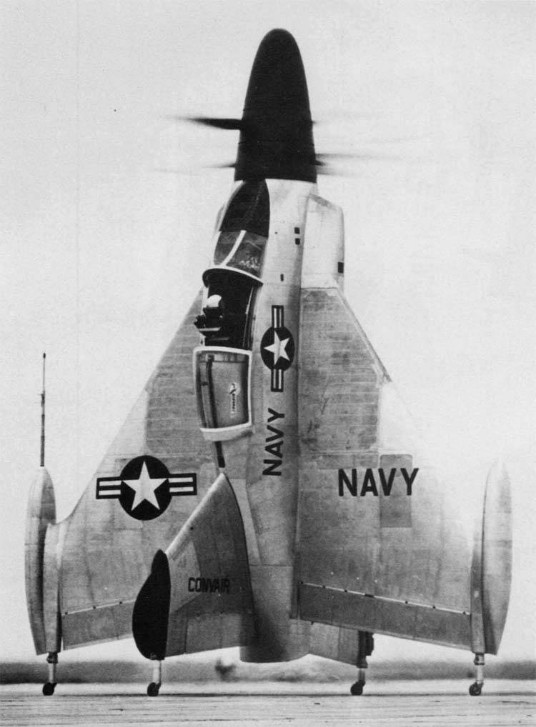
The alleged use of naval forces on ships and other requirements led to the formation of an unusual design of the aircraft. The Tailsitter of the Convair XFV-1, in general, was supposed to resemble existing aircraft, but the basic technical solutions gave it an unusual appearance. The project proposed the construction of a turboprop sredneplan with a large swept wing, devoid of horizontal tail. At the same time, the keel and ventral crest of a large size were to be used. To obtain the required thrust, two large-diameter propellers were used. As a result, the car had a recognizable appearance.
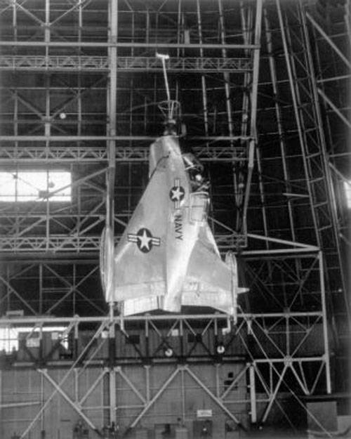
Flight on a leash. Photo 456fis.org
The tailless aircraft received the fuselage of the original design. This unit had a streamlined shape with a variable cross-sectional area. Immediately after the coke and the hub of the screws, the fuselage increased significantly in height, maintaining the original width. The upper part of the fuselage formed a pronounced "hump", necessary to accommodate the pilot's cabin. Behind the lantern was a small length gargrot, on which the keel mounts were placed. Used a very original layout of the fuselage. The nose part was given under the engine gearbox and coaxial screw hub. Behind the gearbox over the bottom of the engine was located. Above it was located pilot's cabin. The tail section of the fuselage contained part of the fuel tanks, as well as a long exhaust pipe of the engine. The latter was displayed on the tail section of the fuselage.
For the aircraft, a new large-swept wing was developed, the root of which occupied most of the sides of the fuselage. On the trailing edge of a small sweep, elevons were placed. The wing received the ending-containers in which there were additional fuel tanks. The used form of the wing allowed to obtain the maximum possible area with limited dimensions.
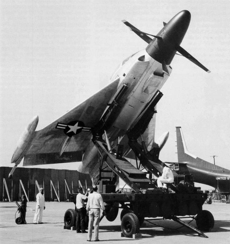
Experienced aircraft on a trolley. Photo Airwar.ru
A characteristic feature of Convair's tailsitter is the large keel and ventral ridge. Thanks to the use of a large wing, it was possible to abandon the stabilizers of the classical design. Stability and controllability in the mode of vertical take-off and travel in horizontal flight should have been ensured, first of all, by vertical tail. Two vertical planes with a swept front edge and a rounded tip were used. On the rear edge of the keel and ridge were the rudders. Both planes were symmetrical about the longitudinal axis of the machine. At the same time, however, due to the asymmetrical design of the fuselage, the keel protruding above it had a smaller area and a different shape of the root part.
In connection with the characteristic position in the parking lot or during takeoff, the aircraft sitting on its tail received the original chassis. Next to the wing wing tips and near the vertical tail tips, there were tubular covers in which there were non-removable landing gear. The aircraft-tailster received a four-bearing chassis with shock absorbers and small wheels. Racks with self-orienting wheels allowed the aircraft to take a vertical position, as well as maneuver when towing.
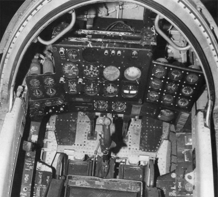
Cabin interior. Photo Airwar.ru
In the central part of the fuselage, directly under the cockpit, there was an Allison YT40-A-6 turboprop engine hp 5100. The flow of atmospheric air to the engine was carried out using two intake devices placed on the sides in front of the edge of the wing. An air intake of radiators was provided on the bottom. A pipe was attached to the nozzle of the engine, reaching the rear fuselage and bringing the reactive gases to the outside. The aircraft was equipped with two coaxial three-bladed screws with a diameter of 4,88 m, developed by Curtiss-Wright. The blades were mounted on a common sleeve of a relatively complex structure. Drive screws equipped with a hydraulic brake.
To manage the machine had one pilot, located in the cockpit. His workplace was equipped with a large instrument panel with switch instruments and several panels with various equipment. Control was to be carried out using standard "destructive" systems: aircraft and engine control knobs, as well as two pedals. The cab received an ejection seat with unusual mounting tools. For greater convenience of work on different modes chair could swing within a wide sector. If unsuccessful landing, the pilot could leave the plane and go down to the ground with a rope of length 25 feet (7,6 m) fixed in the cockpit. From the oncoming flow of the pilot defended a large area lantern. It consisted of a fixed visor and the main part shifted back.
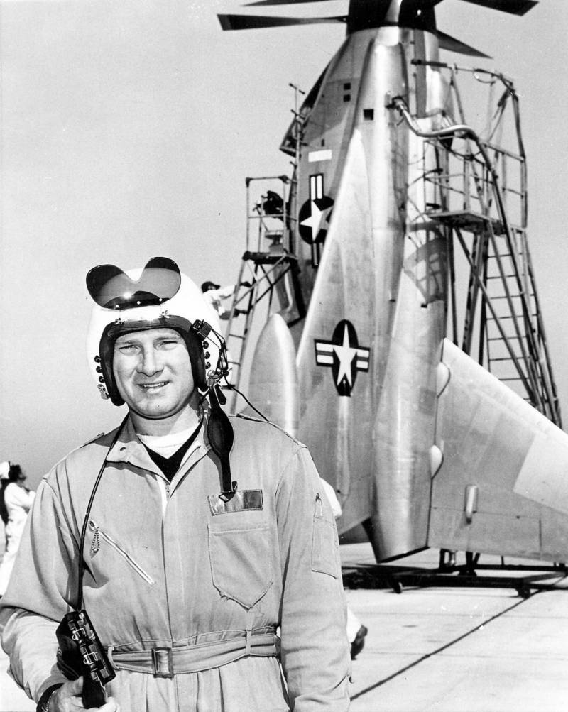
Test Pilot James F. Coleman. Photo by US Navy
The experimental aircraft did not need weaponsHowever, this issue was nevertheless worked out at the design stage. While maintaining the available dimensions and weight parameters, the Convair XFY-1 could carry up to four 20-mm automatic guns or several dozen unguided missiles. Due to the absence of other free volumes, it was proposed to mount them in containers at the ends of the wing.
Despite all efforts to reduce the size, the prospective tailsitter aircraft was quite large. The length of the vehicle reached 10,66 m, the wingspan was 8,43 m. The vertical tail span was about 7 m. The empty aircraft had a mass of 5,33 t, the maximum take-off was determined at the level of 7,37 t. According to calculations, the maximum speed in horizontal flight was to exceed 980 km / h It was planned to obtain high characteristics of climb rate: for this, the screws had to perform the functions of carriers.
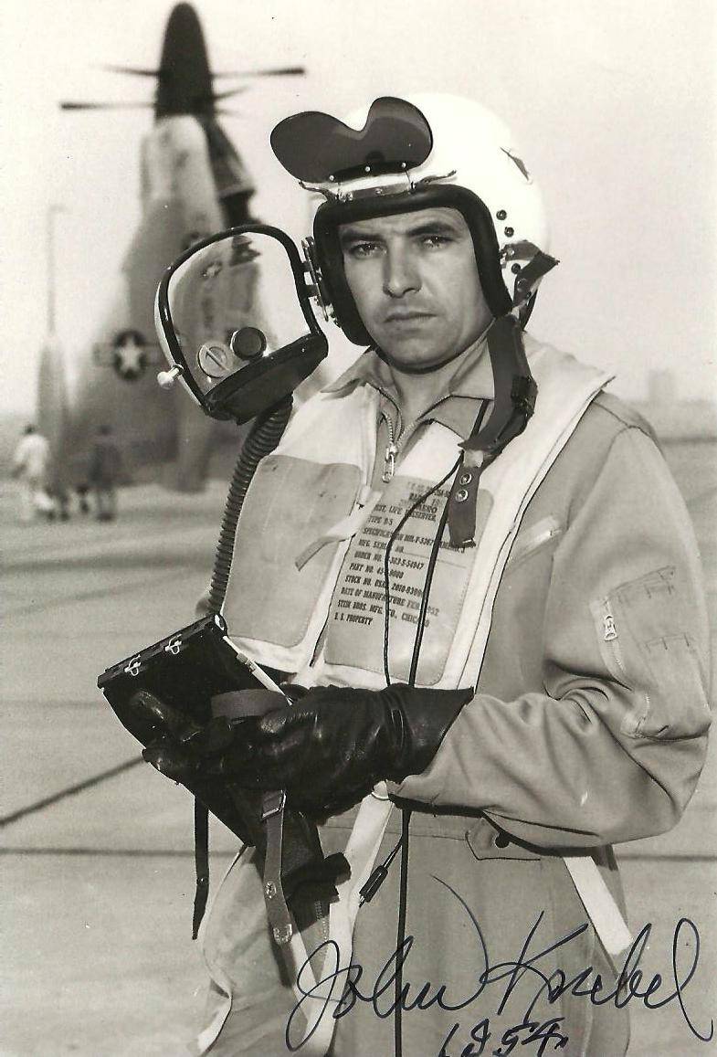
Test pilot John Knebel. Photo Thetartanterror.blogspot.fr
For the transportation of an aircraft having a specific chassis, a special towed trolley was developed. On the frame with four wheels were placed two swinging beams with hydraulic cylinders. At the free ends of the beams with their own hinges and separate drives were fixed smaller holding devices. When loading the aircraft, the latter were brought under its center section and were connected to it with locks. Hydraulics made it possible to transfer the machine to a horizontal position and, with the help of a separate tractor, move the trolley to the desired position. In preparation for takeoff, the aircraft was moved to a vertical position, after which it was disengaged and got onto its own wheels.
At the end of 1953, Convair began building experienced equipment. It was decided to build three identical machines designed to solve various problems within an extensive test program. The first glider should be equipped with a propeller group, fuel system and controls. Such a prototype was intended for preliminary checks of the power plant. The third sample was sent for static tests. Checked on the ground, fly into the air on a leash and make free flights followed the second experienced "teilsitteru."
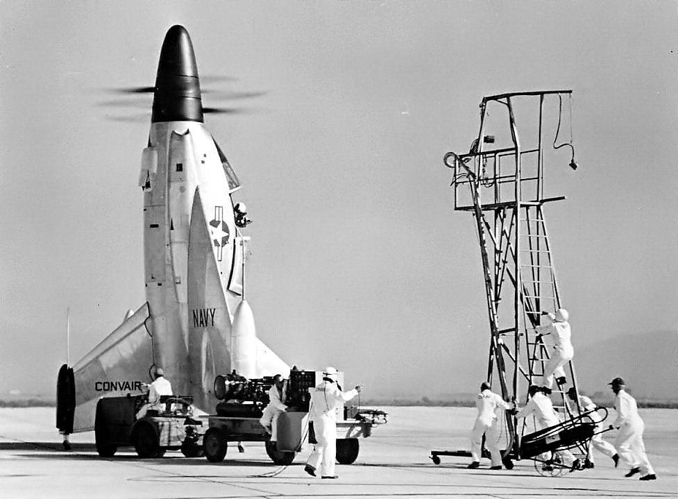
Preparing for takeoff, the engine is running. Photo Airwar.ru
After checking the operation of the engine on the first prototype, permission was obtained to conduct subsequent tests with ground testing of equipment and subsequent ascent into the air. As a platform for these checks, Moffett airfield (California) was chosen, namely, one of its slings, which was built for airships in due time. Under the roof of the boathouse with a height of almost 60, there was a crane beam, which was to become a safety net. Preparing an experienced XFY-1 for flight, the developers of the development company dismantled the screw hub, under which there was a special mounting structure. With the help of the latter, the plane should be hung on a crane hook. By choosing and bleeding the cable, the crane operator could prevent the aircraft from falling.
29 April 1954, the aircraft was first to take to the air using insurance. Pilot James F. Coleman was responsible for managing the prototype machine. Engineer Bob McGriry controlled the crane and controlled the length of the free cable. Having brought the engine to the required power, the test pilot was able to lift the car off the ground, but immediately after that problems began. Once in the air, the aircraft began to rotate uncontrollably around the longitudinal axis. Thanks to the timely response of the engineer-operator of the crane, the car was saved from falling. After the completion of the first test flight, the machine with some difficulty sat down.
The car is parked. Photo Airwar.ru
Probably at this stage, due to the peculiarities of the spring damping of the chassis, the aircraft received the nickname Pogo (from the Pogo-stick - the Grasshopper sports equipment). Subsequently, the informal name of the project became widely known and is now used as often as the official designation assigned by the customer.
The aircraft showed its ability to take off and land vertically, but uncontrolled rotations on these modes did not allow to realize all the advantages of the original scheme. It was necessary to find out the causes of such problems and eliminate them. To do this, the outer surfaces of the airframe were pasted over with “silks”, the observation of which made it possible to identify aerodynamic problems. Such tests quickly gave results. It turned out that even the existing large boathouse was not large enough for an experienced car. The air flow from the screws hit the floor of the building, moved to the sides, was reflected from the walls and came back. It was precisely the numerous whirlwinds that prevented the tail-taker from maintaining the required position.
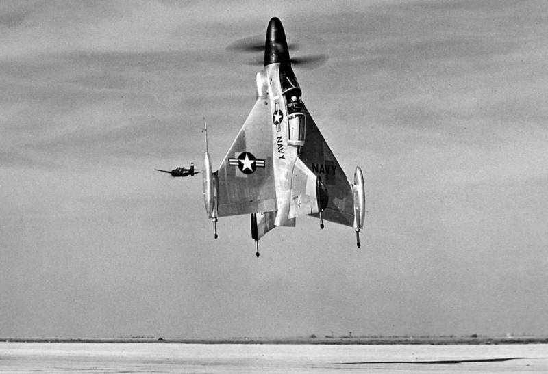
Convair XFY-1 Pogo takes a vertical take-off, 30 November 1954 g. Photo by US Navy
The testers took into account this fact, but were still forced to continue testing in a closed building. The test car still needed insurance, which could only be carried out by a boathouse. The installation of such equipment in an open area was not possible. In such difficult conditions, J.F. Coleman made dozens of test flights with a total duration of about 60 hours. Due to the unstable behavior of the vehicle during the first tests and subsequent flights, the test pilot never closed the flashlight. This caused some inconvenience, but Coleman considered them an acceptable price for being able to quickly leave the aircraft.
In the middle of 1954, the prototype was taken to an open area for free flight. On the very first day of such tests, the test pilot was able to rise to the height of 6 m, and then overcome the bar in 45. The control of the machine was not too simple, but the lack of walls and a roof had a positive effect on the characteristics of the vehicle. Taking advantage of this, J.F. Coleman continued vertical flights with numerous takeoffs, maneuvering "helicopter" and the subsequent landing.
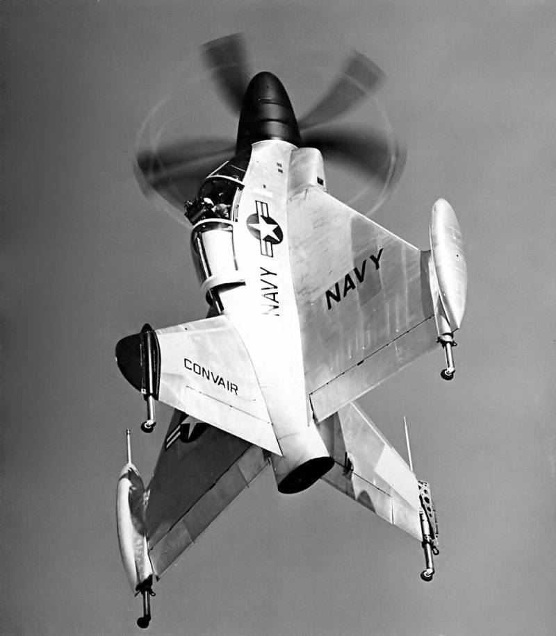
Flying "in helicopter". Photo by US Navy
Soon, an experienced "tailsitter" was transferred to Brown Field airfield (California), where the tests were to continue under the supervision of representatives of the military department. At the new location, another 70 vertical flight was performed, after which it was decided to test the prototype on transient conditions and in horizontal flight.
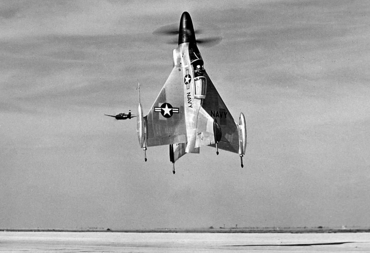
2 November 1954, an experienced XFY-1, flew vertically for the first time and moved to horizontal flight after climbing. After that, the car returned to the vertical position and planted. The flight lasted 21 minute, of which 7 accounted for the flight "on an airplane". The beginning of such checks allowed us to determine the real characteristics of horizontal flight. So, it was found that even with a minimal engine thrust, a tailsitter can reach speeds of more than 480 km / h. The aircraft was not equipped with air brakes, which made it difficult to control the speed. Because of this, he involuntarily repeatedly overtook the understudy aircraft accompanying him.
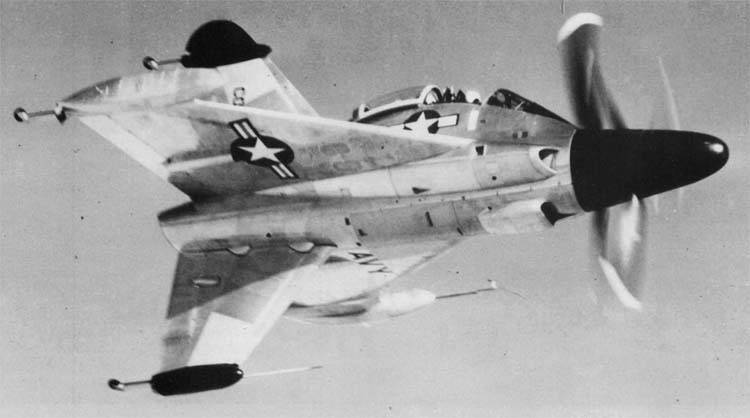
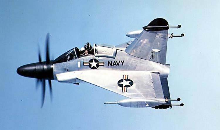
Level flight. Photo Airwar.ru
Confirming the calculated characteristics, the experimental machine showed certain disadvantages. First of all, it was found that XFY-1 is notable for complexity of control, especially in transient conditions. For a safe landing for an experienced pilot J.F. Coleman had to transfer the car to a vertical position at altitudes around 300 m, and then gradually lower it to the ground. The last meters of the descent were associated with particular difficulties, since numerous whirlwinds prevented the landing, and besides, the pilot from his cockpit could not normally monitor the situation. To partially solve this problem, at one of the stages of testing, a prototype received a radio altimeter with a light alarm: green and orange lamps indicated normal descent, and the red indicated the excess vertical safety speed.
J.F. Coleman flew the only Pogo until the middle of 1955. An experienced pilot managed to master all the subtleties of controlling such a machine in complex modes. At the same time, it became clear that ordinary pilots from combatant units could hardly learn how to pilot such equipment. Moreover, such tasks were beyond the power of even professional testers. So, in the middle of May 1955, pilot John Knebel was supposed to join the tests. During his first flight, conducted without insurance, he could not keep the car in the right position and almost broke it. After that, all new flights were entrusted only to Coleman.
Rear-top view. Photo Airwar.ru
16 June 1955 of the year J.F. Coleman last sent an experienced Tailsitter into free flight. After that, the car was sent to the hangar for the time of studying the results of the tests, finalizing the project, etc. In the spring of next year it was decided to conduct new tests by the forces of the naval forces, for which two pilots of naval aviation went for training. However, they never managed to join the work.
During test flights, the only flight model of the Convair XFY-1 Pogo managed to work out most of the resource. During the next test, chips were found in the oil from the gearbox. The machine needed to be repaired and restored before new tests. However, the customer considered the overhaul of the aircraft unnecessary. The original project was no longer of interest to him, because of which the restoration of the prototype’s readiness did not make sense.
"Pogo" in color. Photo Airwar.ru
After examining the success of two pilot projects from the companies Lockheed and Convair, the command of the US Navy made conclusions about the practical benefits of "sitting on the tail" of aircraft. This technique had noticeable advantages over both aircraft and helicopters, but at the same time it was not without its characteristic drawbacks. Tests of the prototype "Pogo" showed that such a machine is very difficult to pilot and demanding landing sites. The management of such equipment could hardly be mastered by an average pilot. In addition, the landing on the rocking deck of the ship was virtually impossible.
Unusual projects were of interest from a technical and scientific point of view. They showed the fundamental possibility of creating aircraft of vertical takeoff of non-standard design. At the same time, these developments had a specific ratio of positive and negative features. Serial production, operation and mass development of such equipment did not make sense.
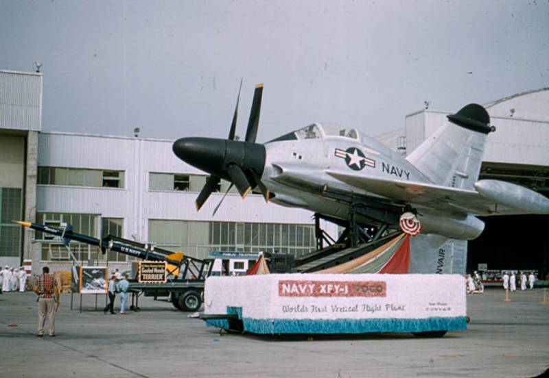
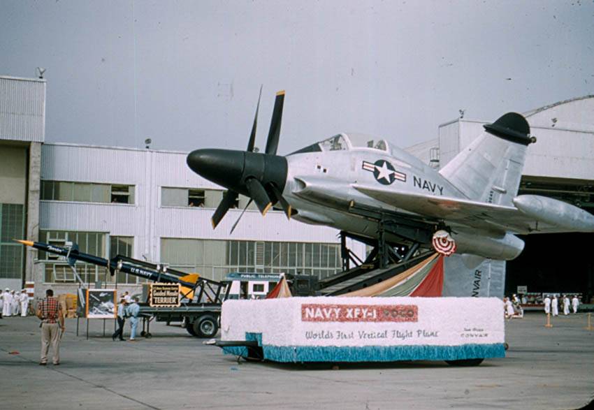
Experimental machine as an exhibit, August 1957. Photo by Wikimedia Commons
In 1956, the XFY-1 project was closed due to the lack of real prospects. The first and third prototypes, intended for ground and static tests, were disassembled as superfluous. The only flying "Pogo" for some time was at the Navy air base in Norfolk (California). He was later transferred to the National Air and Space Museum of the Smithsonian Institution. A unique piece of technology is stored at the branch of the museum in Suitland (Maryland).
The closure of the experimental project Convair XFY-1 led to the completion of work on the subject of aircraft Tailsitter, carried out since the late forties, by the order of the naval forces of the United States. Two projects showed the fundamental possibility of developing and building machinery of unusual appearance, but at the same time they demonstrated the excessive complexity of its operation. It was originally planned that the result of the two projects will be the appearance of a deck fighter, but later these developments were transferred to the category of experimental ones. Two projects successfully solved a similar problem.
On the materials of the sites:
https://airandspace.si.edu/
http://airwar.ru/
https://vertipedia.vtol.org/
http://aviastar.org/
http://diseno-art.com/
http://defensemedianetwork.com/
http://456fis.org/
http://thetartanterror.blogspot.fr
The idea of an aircraft of the type Tailsitter ("Sitting on the tail") emerged from the analysis of the experience of using carrier-based aircraft and a number of new studies. With all its advantages, carrier-based fighters and bombers needed a large aircraft carrier ship and, by definition, could not work without it. At the end of the forties, an original idea was proposed that allowed a fighter to be placed on almost any ship or vessel. It was proposed to develop and build a vertical take-off combat aircraft.
Prototype Convair XFY-1 during testing. Photo 456fis.org
According to the idea of the authors of the new concept, on the ground or on the deck of the carrier ship, the prospective "tailsitter" was to be placed vertically. This allowed him to take off without a takeoff run, and then go to the horizontal flight "in an airplane". Before landing, accordingly, it was necessary to return to vertical flight again. Without the need for a large runway or flight deck, such an aircraft could be based on a variety of ships with sufficient free space. As a result, he was of great interest to the naval forces.
The program to create a promising combat "tailsitter" started in 1948 year. At its first stages, research organizations were engaged in theoretical calculations and experiments, the results of which soon allowed to start creating full-fledged projects. The development of new technology was assigned to two leading aircraft manufacturers - Lockheed and Convair. They had a lot of experience in the creation of aircraft technology, including unusual schemes. Together with the experience of contractors, the companies should have used the data collected in recent studies.
Scheme of the car. Figure Airwar.ru
Initially, contracting companies were faced with a rather difficult task. They had to develop aircraft tailsters suitable for practical use in the armed forces. Then the command of the Navy was going to compare the two samples obtained and select the most successful one. This car was planned to be put into a series and sent to the troops. However, it soon became clear that such an approach to the creation of new military equipment would not be possible to put into practice. At first, it was necessary to test new original ideas during the tests, evaluate their prospects, and only after that take up the creation of a complete combat vehicle.
In this regard, in 1950, Lockheed and Convair received a new task. Now they were required to create experimental aircraft, with the help of which it would be possible to verify the concept of Tailsitter. With a favorable completion of this phase of the project it was possible to undertake the creation of combat aircraft.

Preparation for tests in the hangar. Photo 456fis.org
On April 19, 1951, the U.S. Navy signed contracts for the construction of prototypes. In accordance with the agreement, Convair was to build and submit for testing two prototypes. Subsequently, the company proactively decided to build three cars that were to take on different types of tests. The Convair project at this stage received the official designation XFY-1, formed in accordance with the rules for the name of aircraft fleet. The first letter of the designation indicated the experimental nature of the project, the letter “F” assigned the aircraft to fighter aircraft, and the letter “Y” denoted Convair. The unit, respectively, showed that it was the first project in its lineup.
The alleged use of naval forces on ships and other requirements led to the formation of an unusual design of the aircraft. The Tailsitter of the Convair XFV-1, in general, was supposed to resemble existing aircraft, but the basic technical solutions gave it an unusual appearance. The project proposed the construction of a turboprop sredneplan with a large swept wing, devoid of horizontal tail. At the same time, the keel and ventral crest of a large size were to be used. To obtain the required thrust, two large-diameter propellers were used. As a result, the car had a recognizable appearance.
Flight on a leash. Photo 456fis.org
The tailless aircraft received the fuselage of the original design. This unit had a streamlined shape with a variable cross-sectional area. Immediately after the coke and the hub of the screws, the fuselage increased significantly in height, maintaining the original width. The upper part of the fuselage formed a pronounced "hump", necessary to accommodate the pilot's cabin. Behind the lantern was a small length gargrot, on which the keel mounts were placed. Used a very original layout of the fuselage. The nose part was given under the engine gearbox and coaxial screw hub. Behind the gearbox over the bottom of the engine was located. Above it was located pilot's cabin. The tail section of the fuselage contained part of the fuel tanks, as well as a long exhaust pipe of the engine. The latter was displayed on the tail section of the fuselage.
For the aircraft, a new large-swept wing was developed, the root of which occupied most of the sides of the fuselage. On the trailing edge of a small sweep, elevons were placed. The wing received the ending-containers in which there were additional fuel tanks. The used form of the wing allowed to obtain the maximum possible area with limited dimensions.
Experienced aircraft on a trolley. Photo Airwar.ru
A characteristic feature of Convair's tailsitter is the large keel and ventral ridge. Thanks to the use of a large wing, it was possible to abandon the stabilizers of the classical design. Stability and controllability in the mode of vertical take-off and travel in horizontal flight should have been ensured, first of all, by vertical tail. Two vertical planes with a swept front edge and a rounded tip were used. On the rear edge of the keel and ridge were the rudders. Both planes were symmetrical about the longitudinal axis of the machine. At the same time, however, due to the asymmetrical design of the fuselage, the keel protruding above it had a smaller area and a different shape of the root part.
In connection with the characteristic position in the parking lot or during takeoff, the aircraft sitting on its tail received the original chassis. Next to the wing wing tips and near the vertical tail tips, there were tubular covers in which there were non-removable landing gear. The aircraft-tailster received a four-bearing chassis with shock absorbers and small wheels. Racks with self-orienting wheels allowed the aircraft to take a vertical position, as well as maneuver when towing.
Cabin interior. Photo Airwar.ru
In the central part of the fuselage, directly under the cockpit, there was an Allison YT40-A-6 turboprop engine hp 5100. The flow of atmospheric air to the engine was carried out using two intake devices placed on the sides in front of the edge of the wing. An air intake of radiators was provided on the bottom. A pipe was attached to the nozzle of the engine, reaching the rear fuselage and bringing the reactive gases to the outside. The aircraft was equipped with two coaxial three-bladed screws with a diameter of 4,88 m, developed by Curtiss-Wright. The blades were mounted on a common sleeve of a relatively complex structure. Drive screws equipped with a hydraulic brake.
To manage the machine had one pilot, located in the cockpit. His workplace was equipped with a large instrument panel with switch instruments and several panels with various equipment. Control was to be carried out using standard "destructive" systems: aircraft and engine control knobs, as well as two pedals. The cab received an ejection seat with unusual mounting tools. For greater convenience of work on different modes chair could swing within a wide sector. If unsuccessful landing, the pilot could leave the plane and go down to the ground with a rope of length 25 feet (7,6 m) fixed in the cockpit. From the oncoming flow of the pilot defended a large area lantern. It consisted of a fixed visor and the main part shifted back.

Test Pilot James F. Coleman. Photo by US Navy
The experimental aircraft did not need weaponsHowever, this issue was nevertheless worked out at the design stage. While maintaining the available dimensions and weight parameters, the Convair XFY-1 could carry up to four 20-mm automatic guns or several dozen unguided missiles. Due to the absence of other free volumes, it was proposed to mount them in containers at the ends of the wing.
Despite all efforts to reduce the size, the prospective tailsitter aircraft was quite large. The length of the vehicle reached 10,66 m, the wingspan was 8,43 m. The vertical tail span was about 7 m. The empty aircraft had a mass of 5,33 t, the maximum take-off was determined at the level of 7,37 t. According to calculations, the maximum speed in horizontal flight was to exceed 980 km / h It was planned to obtain high characteristics of climb rate: for this, the screws had to perform the functions of carriers.
Test pilot John Knebel. Photo Thetartanterror.blogspot.fr
For the transportation of an aircraft having a specific chassis, a special towed trolley was developed. On the frame with four wheels were placed two swinging beams with hydraulic cylinders. At the free ends of the beams with their own hinges and separate drives were fixed smaller holding devices. When loading the aircraft, the latter were brought under its center section and were connected to it with locks. Hydraulics made it possible to transfer the machine to a horizontal position and, with the help of a separate tractor, move the trolley to the desired position. In preparation for takeoff, the aircraft was moved to a vertical position, after which it was disengaged and got onto its own wheels.
At the end of 1953, Convair began building experienced equipment. It was decided to build three identical machines designed to solve various problems within an extensive test program. The first glider should be equipped with a propeller group, fuel system and controls. Such a prototype was intended for preliminary checks of the power plant. The third sample was sent for static tests. Checked on the ground, fly into the air on a leash and make free flights followed the second experienced "teilsitteru."
Preparing for takeoff, the engine is running. Photo Airwar.ru
After checking the operation of the engine on the first prototype, permission was obtained to conduct subsequent tests with ground testing of equipment and subsequent ascent into the air. As a platform for these checks, Moffett airfield (California) was chosen, namely, one of its slings, which was built for airships in due time. Under the roof of the boathouse with a height of almost 60, there was a crane beam, which was to become a safety net. Preparing an experienced XFY-1 for flight, the developers of the development company dismantled the screw hub, under which there was a special mounting structure. With the help of the latter, the plane should be hung on a crane hook. By choosing and bleeding the cable, the crane operator could prevent the aircraft from falling.
29 April 1954, the aircraft was first to take to the air using insurance. Pilot James F. Coleman was responsible for managing the prototype machine. Engineer Bob McGriry controlled the crane and controlled the length of the free cable. Having brought the engine to the required power, the test pilot was able to lift the car off the ground, but immediately after that problems began. Once in the air, the aircraft began to rotate uncontrollably around the longitudinal axis. Thanks to the timely response of the engineer-operator of the crane, the car was saved from falling. After the completion of the first test flight, the machine with some difficulty sat down.
The car is parked. Photo Airwar.ru
Probably at this stage, due to the peculiarities of the spring damping of the chassis, the aircraft received the nickname Pogo (from the Pogo-stick - the Grasshopper sports equipment). Subsequently, the informal name of the project became widely known and is now used as often as the official designation assigned by the customer.
The aircraft showed its ability to take off and land vertically, but uncontrolled rotations on these modes did not allow to realize all the advantages of the original scheme. It was necessary to find out the causes of such problems and eliminate them. To do this, the outer surfaces of the airframe were pasted over with “silks”, the observation of which made it possible to identify aerodynamic problems. Such tests quickly gave results. It turned out that even the existing large boathouse was not large enough for an experienced car. The air flow from the screws hit the floor of the building, moved to the sides, was reflected from the walls and came back. It was precisely the numerous whirlwinds that prevented the tail-taker from maintaining the required position.
Convair XFY-1 Pogo takes a vertical take-off, 30 November 1954 g. Photo by US Navy
The testers took into account this fact, but were still forced to continue testing in a closed building. The test car still needed insurance, which could only be carried out by a boathouse. The installation of such equipment in an open area was not possible. In such difficult conditions, J.F. Coleman made dozens of test flights with a total duration of about 60 hours. Due to the unstable behavior of the vehicle during the first tests and subsequent flights, the test pilot never closed the flashlight. This caused some inconvenience, but Coleman considered them an acceptable price for being able to quickly leave the aircraft.
In the middle of 1954, the prototype was taken to an open area for free flight. On the very first day of such tests, the test pilot was able to rise to the height of 6 m, and then overcome the bar in 45. The control of the machine was not too simple, but the lack of walls and a roof had a positive effect on the characteristics of the vehicle. Taking advantage of this, J.F. Coleman continued vertical flights with numerous takeoffs, maneuvering "helicopter" and the subsequent landing.

Flying "in helicopter". Photo by US Navy
Soon, an experienced "tailsitter" was transferred to Brown Field airfield (California), where the tests were to continue under the supervision of representatives of the military department. At the new location, another 70 vertical flight was performed, after which it was decided to test the prototype on transient conditions and in horizontal flight.
2 November 1954, an experienced XFY-1, flew vertically for the first time and moved to horizontal flight after climbing. After that, the car returned to the vertical position and planted. The flight lasted 21 minute, of which 7 accounted for the flight "on an airplane". The beginning of such checks allowed us to determine the real characteristics of horizontal flight. So, it was found that even with a minimal engine thrust, a tailsitter can reach speeds of more than 480 km / h. The aircraft was not equipped with air brakes, which made it difficult to control the speed. Because of this, he involuntarily repeatedly overtook the understudy aircraft accompanying him.
Level flight. Photo Airwar.ru
Confirming the calculated characteristics, the experimental machine showed certain disadvantages. First of all, it was found that XFY-1 is notable for complexity of control, especially in transient conditions. For a safe landing for an experienced pilot J.F. Coleman had to transfer the car to a vertical position at altitudes around 300 m, and then gradually lower it to the ground. The last meters of the descent were associated with particular difficulties, since numerous whirlwinds prevented the landing, and besides, the pilot from his cockpit could not normally monitor the situation. To partially solve this problem, at one of the stages of testing, a prototype received a radio altimeter with a light alarm: green and orange lamps indicated normal descent, and the red indicated the excess vertical safety speed.
J.F. Coleman flew the only Pogo until the middle of 1955. An experienced pilot managed to master all the subtleties of controlling such a machine in complex modes. At the same time, it became clear that ordinary pilots from combatant units could hardly learn how to pilot such equipment. Moreover, such tasks were beyond the power of even professional testers. So, in the middle of May 1955, pilot John Knebel was supposed to join the tests. During his first flight, conducted without insurance, he could not keep the car in the right position and almost broke it. After that, all new flights were entrusted only to Coleman.
Rear-top view. Photo Airwar.ru
16 June 1955 of the year J.F. Coleman last sent an experienced Tailsitter into free flight. After that, the car was sent to the hangar for the time of studying the results of the tests, finalizing the project, etc. In the spring of next year it was decided to conduct new tests by the forces of the naval forces, for which two pilots of naval aviation went for training. However, they never managed to join the work.
During test flights, the only flight model of the Convair XFY-1 Pogo managed to work out most of the resource. During the next test, chips were found in the oil from the gearbox. The machine needed to be repaired and restored before new tests. However, the customer considered the overhaul of the aircraft unnecessary. The original project was no longer of interest to him, because of which the restoration of the prototype’s readiness did not make sense.
"Pogo" in color. Photo Airwar.ru
After examining the success of two pilot projects from the companies Lockheed and Convair, the command of the US Navy made conclusions about the practical benefits of "sitting on the tail" of aircraft. This technique had noticeable advantages over both aircraft and helicopters, but at the same time it was not without its characteristic drawbacks. Tests of the prototype "Pogo" showed that such a machine is very difficult to pilot and demanding landing sites. The management of such equipment could hardly be mastered by an average pilot. In addition, the landing on the rocking deck of the ship was virtually impossible.
Unusual projects were of interest from a technical and scientific point of view. They showed the fundamental possibility of creating aircraft of vertical takeoff of non-standard design. At the same time, these developments had a specific ratio of positive and negative features. Serial production, operation and mass development of such equipment did not make sense.
Experimental machine as an exhibit, August 1957. Photo by Wikimedia Commons
In 1956, the XFY-1 project was closed due to the lack of real prospects. The first and third prototypes, intended for ground and static tests, were disassembled as superfluous. The only flying "Pogo" for some time was at the Navy air base in Norfolk (California). He was later transferred to the National Air and Space Museum of the Smithsonian Institution. A unique piece of technology is stored at the branch of the museum in Suitland (Maryland).
The closure of the experimental project Convair XFY-1 led to the completion of work on the subject of aircraft Tailsitter, carried out since the late forties, by the order of the naval forces of the United States. Two projects showed the fundamental possibility of developing and building machinery of unusual appearance, but at the same time they demonstrated the excessive complexity of its operation. It was originally planned that the result of the two projects will be the appearance of a deck fighter, but later these developments were transferred to the category of experimental ones. Two projects successfully solved a similar problem.
On the materials of the sites:
https://airandspace.si.edu/
http://airwar.ru/
https://vertipedia.vtol.org/
http://aviastar.org/
http://diseno-art.com/
http://defensemedianetwork.com/
http://456fis.org/
http://thetartanterror.blogspot.fr
Information