The project complex "weapon / cartridge" GX-6
Until the beginning of the 20 century, shooting from a gunshot weapons It was conducted by single shots, in the process of which the arrows were able to keep the weapon on the aiming line right up to the moment of the bullet's departure from the barrel with the subsequent adjustment of aiming at the target. The creation of the first models of automatic weapons revealed a common problem for them - the impossibility of aimed firing in bursts due to the fact that the previous shot knocked the weapon off the aiming line before the next shot.
For machine guns, the problem of aimed fire bursts was solved by using massive machine tools with emphasis on the ground and the transition to defeat mainly group targets. Unlike machine guns, individual automatic weapons of the type of the machine gun / assault rifle are designed for maneuvering tactics with frequent movements, shooting from awkward positions, accompanied by keeping the weapon on the weight with the force of the arm muscles and compensating for recoil using the butt support to the shoulder. In this regard, individual automatic weapons are limited in weight and recoil force, which are determined by the physical capabilities of the middle-trained shooters, who constitute the majority of infantry units.
The shooter in the process of firing a queue experiencing multidirectional power effects falling on his hands and body. At the beginning of each shot, the maximum magnitude recoil momentum acts. After the shutter opens and a short period of uniform action of the recoil force compressing the return spring, the arrow is affected by the second impulse associated with the impact of the bolt into the rear wall of the receiver. The cycle of reloading the weapon continues with the second period of uniform action of the elastic force of the return spring and ends with the third impulse directed forward and connected with the impact of the bolt into the barrel. At the same time, the weapon experiences cyclic oscillations from moving its center of gravity associated with the reciprocating movement of the shutter. The situation is aggravated by the fact that in most models of weapons, the axis of the barrel, along which the recoil force acts, does not coincide with the axis of symmetry of the butt, which rests on the shooter’s shoulder. The recoil force and the reaction force of the support create a moment that flips up the barrel.
In the case of the use of the gas-discharge mechanism of reloading, the weapon receives additional oscillations from the impact of high-pressure gas into the bolt carrier and the bolt carrier into the bolt. The refusal of the bolt rigidly coupled with the barrel, and the transition to the free gate, in the case of maintaining the same energy characteristics of the cartridges, leads to a multiple increase in the rate of fire. To ensure an acceptable rate of ammunition at a rate of firing is possible only by increasing the inertial mass of the bolt and reducing the muzzle energy of the weapon. An increase in the inertial mass of the bolt causes an increase in the amplitude of cyclic oscillations of the weapon, and a decrease in the muzzle energy makes shooting at a medium distance ineffective, which indicates that the transition to a free gate is deadlocked.
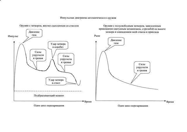
On the basis of the impulse diagram, the aimed shooting with bursts from uncomfortable positions depends on the level of implementation of the following technical solutions in an individual automatic weapon:
- reducing the magnitude of the maximum recoil momentum by moving from a closed to a semi-free gate, starting to move back from the very beginning of the propellant in the barrel, the shot should be made on the vykaty shutter:
- elimination of the throwing moment by raising the axis of symmetry of the butt to the level of the axis of the barrel with a corresponding upward movement of the line of sight of the aiming devices;
- compensation of mass movement of the moving parts of the reloading mechanism due to oncoming movement of the balance bar;
- the elimination of the blows of the bolt against the barrel and receiver.
The first two solutions are fully or partially implemented in the adopted models of individual automatic weapons. The latter solution does not have an effective implementation in existing weapons designs. In the well-known scheme of balanced automation, simultaneously with the bolt, the balance bar moves in the opposite direction, colliding with the bolt in extreme positions. This solution has a fundamental disadvantage - in order to synchronize the movement of the shutter and the balancer, a gear-and-pinion gear is used, experiencing alternating loads in the process of working, causing gear teeth to be chipped, which reduces the life of the reloading mechanism relative to the life of the remaining parts of the weapon. In addition, the balancer, the mass of which is equal to the sum of the masses of the moving elements of the reloading mechanism, increases the weight of the hand weapon by more than a quarter.
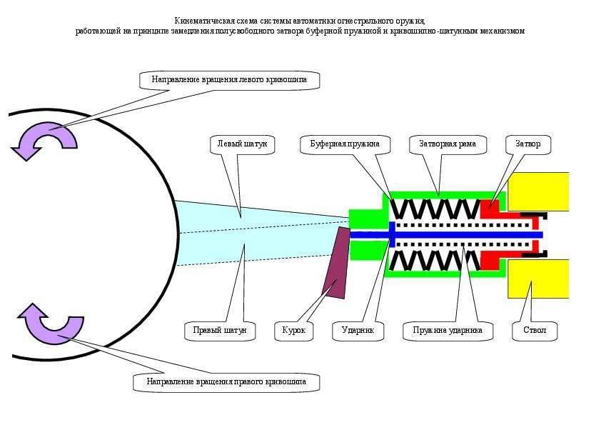
The principal decision is the transition to a semi-free shutter with a crank-drive reloading mechanism, combining the functions of slowing the shutter, eliminating the blows of the bolt against the barrel and the receiver, compensating for the displacement of the center of gravity of the moving elements of the reloading mechanism and increasing its resource to the level of the barrel resource.
History the use of a crank mechanism in automatic firearms has its origin in the patent of Austro-Hungarian designer Emil von Skoda from 1891, which proposed to use a flywheel connected by a crank gear with a movable barrel during a shot. In 1904, the German designer Andreas Schwarzlose patented a solution with a semi-free shutter, a slowed-down longitudinally movable balance bar connected to the shutter with a breaking crankshaft gear lever. The design was implemented in the machine gun M. 07 / 12, produced in large series in various versions from 1905 to 1939 year in Austria-Hungary, Czechoslovakia, Holland and Poland.
Finally, in 1937, the Soviet designer Yuri Fedorovich Yurchenko created a fully-functional firearm automation system with a half-free bolt, slowed down exclusively by a crank mechanism with rotating balancers. In the first half of 1941, a small series were produced at the Kovrov Mechanical Plant aviation machine gun Yu-7.62. The maximum rate of fire was 3600 rounds per minute. Due to its record level, the rifle barrel resource did not exceed 1000 rounds, the barrel required replacement after several sorties, which was considered acceptable in the conditions of the first stage of the war. Subsequently, in connection with the transition of military aircraft to cannon armament, the release of machine guns Yu-7.62 was discontinued.
The Yurchenko automation system includes a semi-free bolt connected by a connecting rod to a connecting rod neck, connecting two cranks, rotating in the same direction, equipped with balancers and mounted opposite one another in special ring-shaped thickenings of the receiver. The cranks are strictly axially located relative to the axis of the trunk. Their mass and diameter are minimized to reduce the weight and dimensions of the machine gun, as well as to achieve the highest possible rate of fire required for aircraft weapons. The shot is made on the vykat of the shutter when the cranks of 5 degrees are not attained to the top dead center of their rotation. Under the action of the recoil force transmitted from the bolt through the crank, the cranks rotate 350 degrees to the second point of the production of shots, after which the cycle of the reloading mechanism is repeated until the trigger is released.
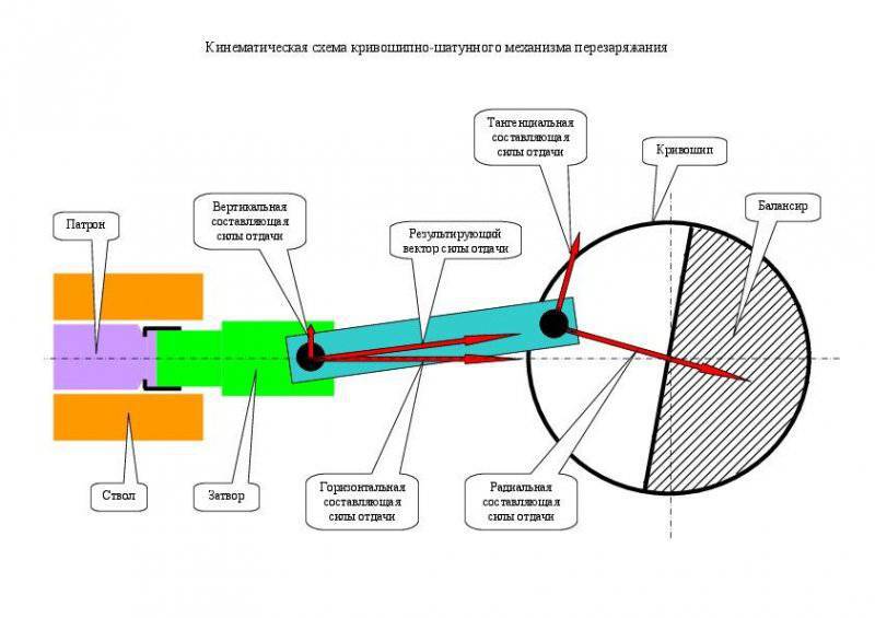
The horizontally directed recoil force acting along the axis of the barrel is converted by the connecting rod into a vertical component acting on the guides of the receiver and into the resultant vector transmitted along the axis of symmetry of the connecting rod to the neck of the cranks. At this point, the resulting vector is transformed into a tangential component of the recoil force (generating torque of the cranks) and the radial component of the recoil force (generating the support reaction). The rotational speed of the cranks varies sinusoidally with the first maximum reaching the top dead center and the second maximum (the value of which is less than the first maximum taking into account the energy consumption for compressing the return spring) at the bottom dead center. The speed of the reciprocating motion of the shutter also varies sinusoidally with a shift of the highs and lows by 90 degrees.
At the bottom dead center of rotation of the cranks, unstressed stop and reversal of the movement of the shutter against the background of continuing rotation of the crank in a given direction, followed by acceleration of all moving elements of the reloading mechanism due to recharge energy from the expanding return spring occur. On the approach to the top dead center, the shutter speed slows down to almost zero, followed by its movement reversing due to the pressure of the powder gases from the combustion of the propellant charge of the cartridge. This also reverses the rotation of the crank. In the event of a misfire of the cartridge, the bolt rests against the breech slice, supported by a return spring. The stop point of the bolt into the barrel corresponds to the 1 degree of underdrive of the cranks to the top dead center. Turnover cranks between points 5 and 1 degrees corresponds to the time of combustion of the propellant charge of the cartridge. In this regard, the shot is made with the shutter almost stopped and the cranks continue to roll out.
In order to implement a balanced automation scheme, the effective diameter of the cranks, equal to twice the distance from the axis of the neck to the axis of rotation of the cranks, must coincide with the working stroke of the shutter between the front and rear end positions. The weight of the crank balancers must correspond to the total mass of the bolt with the connecting rod, corrected for the distance of the center of mass of the balancers from the axis of rotation of the cranks. Only in this case will the movement of the weapon's center of gravity be fully compensated during the operation of the reloading mechanism.
However, these linear dimensions and the mass of moving parts, sufficient for perceiving loads from the recoil force and ensuring the balance of automation, are unacceptable for the case of handguns, since the amount of torque transmitted from the semi-free valve to the cranks causes a shooting rate of several thousand rounds per minute . Reducing the rate of fire to the standard level in 600 rounds per minute will require a multiple increase in weight and / or linear dimensions of the moving parts. In addition, cyclical reversal of cranks rotating in one direction, on the way to the top dead center, leads to the emergence of a reactive moment alternately flipping / tilting a weapon.
The Yurchenko automation system requires substantial revision in order to be used in handguns. The most obvious solution is to switch from two cranks rotating in one direction to two cranks rotating in different directions. In the latter case, the reactive moments arising from the reversal of rotation, will mutually compensate each other. A more nontrivial solution is a method of reducing the torque applied to the cranks during the combustion process of the propellant charge of the cartridge, which is a fundamental point in the matter of using a crank mechanism in a handgun. As such, it is proposed to use the opportunity created by the kinematics of the crank mechanism itself, namely by slowing down to almost zero the rate of translational movement of the shutter when it approaches the top dead center.
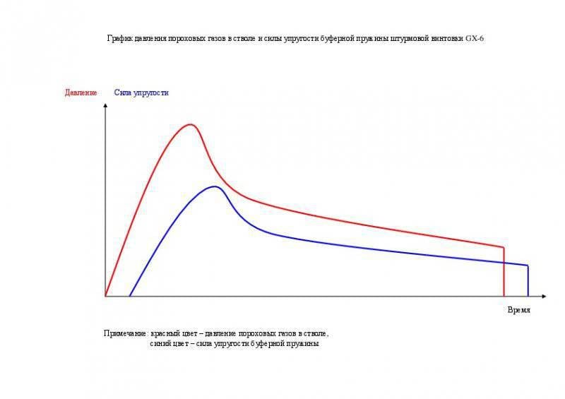
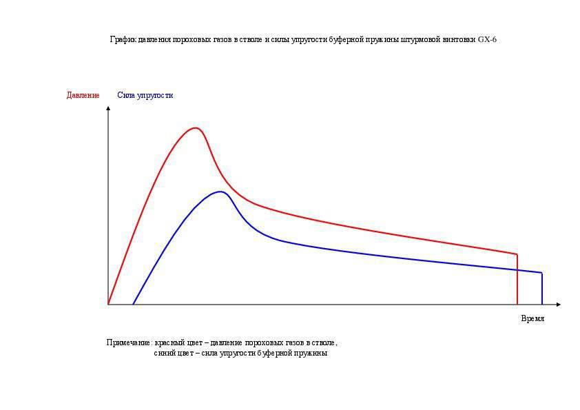
In order to realize this possibility, it is necessary to divide the bolt into the stem and bolt carrier. The stem should be made in the form of a free gate (hereinafter referred to as a shutter), slowed down only by the inertia of its mass and the strength of the buffer spring resting on the bolt carrier. In turn, the slide frame at the approach to the top dead center will be slowed down by a crank mechanism according to its kinematics. The pressure of the powder gases will act on the gate, overcoming its inertia and the elastic force of the buffer spring. A pressure not exceeding the rigidity of the buffer spring in compression will be transmitted to the gate frame, up to the stop of the gate face in the gate frame. The mass of the moving elements and the degree of elasticity of the buffer spring should provide a distance in time of the moment of emphasis by an amount sufficient for the peak of the pressure of the powder gases in the barrel to decrease, thereby reducing the amount of torque applied to the cranks. Based on the maximum pressure in the barrel in 4000 bar and maximum recoil force in 2880 kgf, you can estimate the total mass of the bolt in 50 grams with the maximum spring elasticity in 1000 kgf. The stroke of the shutter will be about 5 mm. Removing the load from the buffer spring will occur under conditions of backpressure of the powder gases, so the force of the blow backward impact on the bolt carrier will not exceed the tensile strength of their structural material.
However, the final decision can only be considered a transition to a new type of unitary cartridge, designed to roll back at the peak pressure of powder gases. The cartridge case must be cylindrical in shape to eliminate the danger of detachment of a Dult or skate. To connect the bullet and the liner it is necessary to use a piece of pressed propellant with an open end. As a structural material of the sleeve, an antifriction material should be used, which multiply reduces the coefficient of friction of the sleeve against the barrel chamber compared to brass or steel.
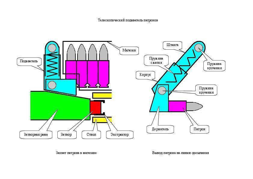
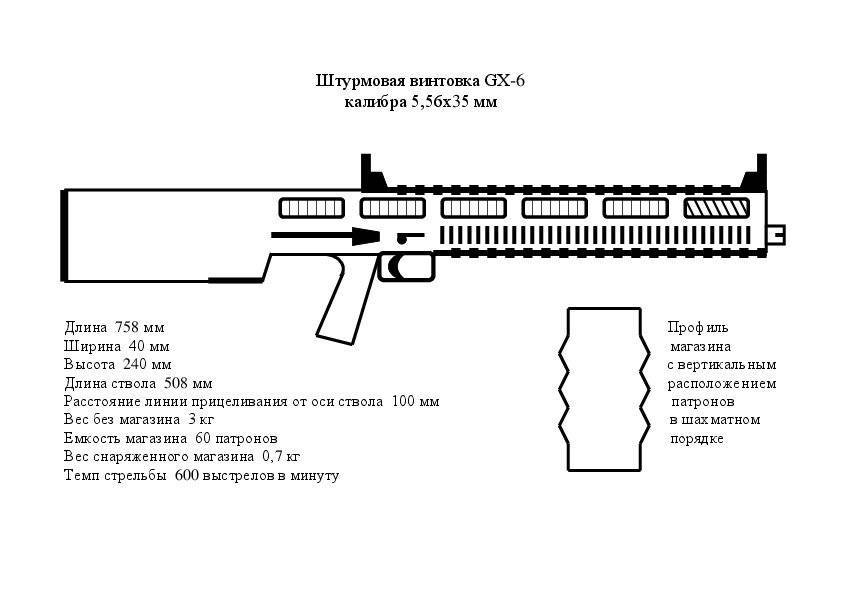
In connection with the above, an innovative project of the “weapon / cartridge” complex under the title GX-6 is proposed. The complex includes an assault rifle and a low-pulse cartridge to it. A magazine with cartridges is placed on top along the barrel. The cartridges in the store are staggered in an upright position, with bullets pointing upwards and rebuilding one row at the exit of the store.
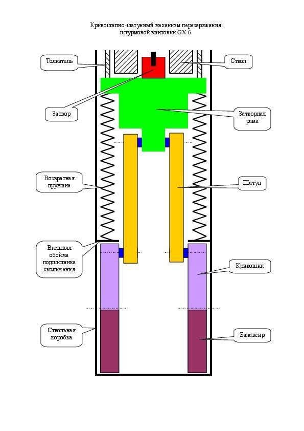
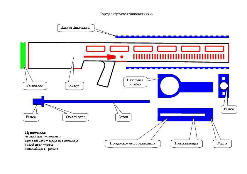
The assault rifle is made according to the bullpup scheme in order to accommodate the overall elements of the reloading mechanism in the butt. The basis of the layout of the crank mechanism is the receiver, connected by a threaded connection with the barrel. In the body of the box there are seats for cranks and guides for the shutter. The barrel has a return thread and an axial stop located in the breech. The barrel and receiver are hung relative to the body of the weapon, connecting with it in the area of the neck of the butt.
The cranks are made in the form of metal cups of small height, in one half of which there are removable fingers for fastening the connecting rods, in the other half there are balancers. The side walls of the glasses serve as an inner sleeve bearing housing. The cranks are installed with a fit in the annular projections of the receiver, which serve as the outer sleeves of the bearings. Each crank connects to its connecting rod. The other side of the connecting rods are attached to the fixed fingers, located on the shank of the bolt carrier.

A clutch is placed in the front end of the bolt box, inside of which is applied the upper and lower sectors of the screw thread with two smooth sections between them. On both sides of the coupling there are also openings for the passage of the pushers supported on the slide frame. Folding handles of manual reloading of the weapon are mounted on opposite ends of the pushers; they are pressed by their own compression springs to the body of the weapon in order to avoid spontaneous movement during firing. To ensure the opposite rotation of the cranks after they stand in the bottom dead center, the length of the pushers is chosen less than the length of the working stroke of the slide frame. On each side wall of the box, between the coupling and the crank bore, there passes a pair of knife guides of the slide frame, simultaneously acting as stiffeners. The guides are spaced in height by the diameter of one of the two return springs located between them.
The bolt carrier in the plan has a T-shape and is made of a solid metal billet by milling. The shoulders of the bolt carrier rests on the return spring, the side surfaces in contact with the guides of the receiver. At the front end of the frame there is a hole for the bolt, at the rear end there is a hole for the drummer. On the side surfaces of the shank are fixed removable connecting rod fingers. The front of the upper surface of the frame has a bevel facing the trunk.
The shutter is made in the form of a stem, the back of which is immersed in the body of the bolt carrier, the front part is equipped with two horizontal extractors. At the rear end of the shutter there is an annular protrusion, limiting the movement of the shutter inside the frame. Between the annular protrusion and the rear wall of the frame there is a buffer spring in the form of an assembly of cup springs made of a titanium spring alloy, which has a threefold load capacity compared to the steel equivalent. Inside the gate there is an inertial hammer with its compression spring, which is activated by means of a trigger of a firing mechanism.
The crank mechanism is assembled in the following order. In the factory, they connect the bolt carrier with the bolt, buffer spring, hammer, and hammer spring, and also install the cranks into the seats of the receiver. Then put the rods on the fingers of the shank of the frame. Return springs are placed between the guides of the receiver. Through the sleeve coupling into the box enter the bolt carrier with rods. The opposite ends of the connecting rods connect removable fingers with cranks.
Submission of cartridges to the line of filing and removal of spent cartridges is carried out in the direction from top to bottom. The open end of the store rests on the retainer located next to the telescopic cartridge feeder, hinged above the bolt carrier. The free end of the feeder is equipped with horizontal grippers that fit into the groove of the cartridge case located at the outlet of the magazine. Inside the feeder is placed a coil spring, which ensures the separation of parts of its telescopic body. The hinge suspension and feeder grips are equipped with torsion springs, which provide deflection of the suspension and clamps at an angle of 45 degrees in the direction of, respectively, back and forth.
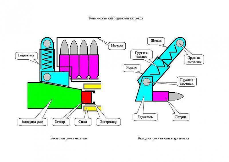
In the extreme forward position, the bolt carrier, with its bevel on the upper surface, presses the feeder up to the stop. After the frame rolls back to the rearmost position, the coil spring pushes the two parts of the telescopic feeder, thus reflecting the gun case down. The torsion springs unfold the body and the grippers of the feeder to the position of withdrawal of the cartridge to the disassembly line. During the reverse movement of the bolt carrier, vertical extractors of the bolt enter the groove of the cartridge case, move the horizontal grippers of the feeder apart and send the cartridge into the barrel. Shutter extractors provide constant clamping of the bottom of the sleeve to the mirror of the shutter until its reflection at the end of the cycle of reloading the weapon.
The body of the assault rifle consists of a casing and a rubber butt pad. The casing is made of glass-filled polymer. In front of the casing in two tiers there are spaces for placing a translucent magazine and a barrel, on the side surfaces of which cuts are made, respectively, to control the presence of cartridges in the magazine and to cool the barrel. Between the tiers on the side surfaces of the casing there are two guides for the magazine. The front and rear ends of the housing are open. In the middle part of the casing there is a pistol type control handle. In the lower part of the butt there is an ejector hole to remove the spent cartridges and the axial cartridges. The ejector hole is closed by a protective curtain that opens when the bolt carrier rolls back. Metal Picatinny trims are mounted on the rivets above and below in the front part of the casing. They are intended for fastening including mechanical and optical sighting devices.
The modular firing mechanism is located inside the control handle and includes a guard, trigger, double-sided fuse / firing mode selector and two longitudinal thrusts, which set the trigger in motion, installed separately under the receiver.
The following metal embedded parts are mounted inside the casing:
- sleeve mounting stem and receiver;
- sleeve mounting the muffler with internal sector thread;
- strap attachment trigger;
- bearing strips for manual reload handles pushers;
- strap fastening latch store and telescopic feeder cartridges;
- a level of fastening of a cock and a protective curtain.

Assembling an assault rifle is performed in the following sequence. At the beginning of the inside of the casing, the firing mechanism, cartridge feeder, trigger and protective curtain are installed. Then, the receiver and the barrel are inserted into the casing from the front and rear, which come together while simultaneously supporting the ends of the box coupling and the axial support of the barrel into the mounting sleeve. In conclusion, a rubber butt plate rests elastically in the rear end of the casing, resting on the receiver box. As a result of the direct transfer of the stop of the receiver through the butt plate into the shoulder of the shooter, the non-metallic casing is completely removed from the compressive load of the recoil force. When firing without stopping the butt into the shoulder, the case experiences a tensile load in a small area from the back side of the control handle to the point of the trunk stop in the attachment sleeve to the weapon body.
The prerequisite for the transition to a new type of ammunition, optimized for semi-free shutter automation systems, is the emergence of modern construction materials suitable for the manufacture of a nonmetallic sleeve of the unitary cartridge instead of its manufacture from traditional brass and steel.
The sleeve in the cartridge performs several functions:
- ensuring the mechanical strength of the cartridge during operation
- accumulation of heat transferred from the barrel to the cartridge;
- obturation of powder gases when fired.
The rejection of casings and the transition to caseless cartridges leads to a decrease in the thermal barrier of their spontaneous combustion in the barrel to the level of the flash point of the propellant charge, which will always be achieved when conducting intensive automatic fire, an example of which is the Heckler & Koch G11 serial assault rifle.
The use of standard sleeve cartridges in combination with Revelli grooves applied to the barrel chamber surface and designed to reduce friction of the sleeve, in the case of a semi-free valve, leads to an increased gas content of the receiver and unstable operation of the reloading mechanism due to the settling of powder burning on the contact surfaces of moving parts, which It was demonstrated on the example of an experienced manual machine gun Degtyarev-Garanin KB-P-790.
In connection with the above, the innovative cartridge cartridge is proposed to use a carbon-carbon composite obtained by burning a structural foam and pressing it into a billet of a cylindrical sleeve, the fine pores of which are impregnated with a high-molecular silicone resin by sintering. The composite material obtained has a strength at the level of brass and a friction coefficient at the level of graphite, i.e. 3,5 times smaller compared to the friction coefficient of brass. The weight of the composite liner is also reduced several times compared to the metal.
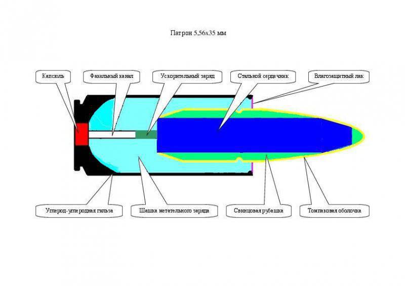
The sleeve has a strictly cylindrical shape with a spherical inner bottom surface, selected from the point of view of excluding stress concentrations in its structure. The diameter of the sleeve welt is less than the diameter of the wall for the thickness of the gate extractors. The bullet of the ogival shape is connected to the sleeve by pressing a propellant charge into the checker, immersed in the sleeve to the level of the edge. The open end of the propellant is coated with nitro lacquer. In the bottom of the liner there is a seat for the primer. In the body of the checker, a flare channel passes from the capsule to the bullet, at the end of which there is an additional accelerator charge, which pushes the bullet out of the checker until the main propellant ignites. As a propellant charge can be used as a nitrocellulose powder and phlegmatized HMX applied in cartridges to the machine gun LSAT, equipped with a plastic sleeve.
The cartridges are loaded into the magazine, the length of which is equal to the length of the rifle barrel. After loading into a weapon the shop does not go beyond the dimensions of the body of the rifle. Spare stores are carried in the shoulder pack,
Tactical and technical characteristics of the assault rifle and ammunition project GX-6:
Caliber - 5,56x35 mm
Sleeve diameter - mm 11,8
Sleeve length - 35 mm
Cartridge length - 50 mm
The weight of one cartridge - 7 grams, including bullet - 4 grams, propellant charge - 2 grams, sleeves - 1 grams
Number of cartridges in the shop - 60 units
Shop weight with cartridges - 700 grams
Weight of a rifle without a magazine - 3000 grams
Firing Rate - 800 shots per minute
Initial bullet speed - 950 m / s
Muzzle Energy - 1800 J
Maximum chamber pressure - 4000 bar
Rifle length - 758 mm
Height - 240 mm
Width - 40 mm
Sighting line length - 400 mm
The distance from the sighting line to the axis of the barrel - 100 mm
Barrel length - 508 mm
Barrel chamber length - 51 mm
Spinning flame arrestor length - mm 48
Butt plate thickness - 20 mm
Jacket Length - 690 mm
Housing shell thickness - 2 mm
The length of the receiver - 220 mm
The thickness of the side wall of the receiver - 3 mm
Return spring diameter - 15 mm (total two units)
Return spring length - 100 mm
Crank Diameter - mm 80
Slide frame length with shutter - 60 mm, including 20 shank mm, 10 shutter mm
Slide frame stroke - 60 mm
Connecting rod length - 80 mm (only two units)
The diameter of the fingers of the rods - mm 10
Gate frame weight assembly with gate and buffer spring - 150 grams
Rod weight - 50 grams
Crank case weight - 50 grams (total 2 units)
Balance weight - 250 grams (total 2 units)
Total weight of the moving parts of the reloading mechanism - 850 grams

The project of the GX-6 complex has an inventive level of technical solutions and is intended for patenting within six months from the date of this publication. In this regard, investors from the number of licensed manufacturers of weapons and ammunition are invited to participate in the project.
Information sources:
Firing tables at ground targets from small arms caliber 5,45 and 7,62 mm. TS GRAU N 61 edition 1977 of the year http://www.ak-info.ru/joomla/index.php/uses/12-spravka/92-shttables77
D.Shiryaev. Record holder. "Weapon" No. 1 for 2007 year http://zonawar.narod.ru/or_2007.html
Patent RU 2193542 http://ru-patent.info/21/90-94/2193542.html
For machine guns, the problem of aimed fire bursts was solved by using massive machine tools with emphasis on the ground and the transition to defeat mainly group targets. Unlike machine guns, individual automatic weapons of the type of the machine gun / assault rifle are designed for maneuvering tactics with frequent movements, shooting from awkward positions, accompanied by keeping the weapon on the weight with the force of the arm muscles and compensating for recoil using the butt support to the shoulder. In this regard, individual automatic weapons are limited in weight and recoil force, which are determined by the physical capabilities of the middle-trained shooters, who constitute the majority of infantry units.
The shooter in the process of firing a queue experiencing multidirectional power effects falling on his hands and body. At the beginning of each shot, the maximum magnitude recoil momentum acts. After the shutter opens and a short period of uniform action of the recoil force compressing the return spring, the arrow is affected by the second impulse associated with the impact of the bolt into the rear wall of the receiver. The cycle of reloading the weapon continues with the second period of uniform action of the elastic force of the return spring and ends with the third impulse directed forward and connected with the impact of the bolt into the barrel. At the same time, the weapon experiences cyclic oscillations from moving its center of gravity associated with the reciprocating movement of the shutter. The situation is aggravated by the fact that in most models of weapons, the axis of the barrel, along which the recoil force acts, does not coincide with the axis of symmetry of the butt, which rests on the shooter’s shoulder. The recoil force and the reaction force of the support create a moment that flips up the barrel.
In the case of the use of the gas-discharge mechanism of reloading, the weapon receives additional oscillations from the impact of high-pressure gas into the bolt carrier and the bolt carrier into the bolt. The refusal of the bolt rigidly coupled with the barrel, and the transition to the free gate, in the case of maintaining the same energy characteristics of the cartridges, leads to a multiple increase in the rate of fire. To ensure an acceptable rate of ammunition at a rate of firing is possible only by increasing the inertial mass of the bolt and reducing the muzzle energy of the weapon. An increase in the inertial mass of the bolt causes an increase in the amplitude of cyclic oscillations of the weapon, and a decrease in the muzzle energy makes shooting at a medium distance ineffective, which indicates that the transition to a free gate is deadlocked.
On the basis of the impulse diagram, the aimed shooting with bursts from uncomfortable positions depends on the level of implementation of the following technical solutions in an individual automatic weapon:
- reducing the magnitude of the maximum recoil momentum by moving from a closed to a semi-free gate, starting to move back from the very beginning of the propellant in the barrel, the shot should be made on the vykaty shutter:
- elimination of the throwing moment by raising the axis of symmetry of the butt to the level of the axis of the barrel with a corresponding upward movement of the line of sight of the aiming devices;
- compensation of mass movement of the moving parts of the reloading mechanism due to oncoming movement of the balance bar;
- the elimination of the blows of the bolt against the barrel and receiver.
The first two solutions are fully or partially implemented in the adopted models of individual automatic weapons. The latter solution does not have an effective implementation in existing weapons designs. In the well-known scheme of balanced automation, simultaneously with the bolt, the balance bar moves in the opposite direction, colliding with the bolt in extreme positions. This solution has a fundamental disadvantage - in order to synchronize the movement of the shutter and the balancer, a gear-and-pinion gear is used, experiencing alternating loads in the process of working, causing gear teeth to be chipped, which reduces the life of the reloading mechanism relative to the life of the remaining parts of the weapon. In addition, the balancer, the mass of which is equal to the sum of the masses of the moving elements of the reloading mechanism, increases the weight of the hand weapon by more than a quarter.
The principal decision is the transition to a semi-free shutter with a crank-drive reloading mechanism, combining the functions of slowing the shutter, eliminating the blows of the bolt against the barrel and the receiver, compensating for the displacement of the center of gravity of the moving elements of the reloading mechanism and increasing its resource to the level of the barrel resource.
History the use of a crank mechanism in automatic firearms has its origin in the patent of Austro-Hungarian designer Emil von Skoda from 1891, which proposed to use a flywheel connected by a crank gear with a movable barrel during a shot. In 1904, the German designer Andreas Schwarzlose patented a solution with a semi-free shutter, a slowed-down longitudinally movable balance bar connected to the shutter with a breaking crankshaft gear lever. The design was implemented in the machine gun M. 07 / 12, produced in large series in various versions from 1905 to 1939 year in Austria-Hungary, Czechoslovakia, Holland and Poland.
Finally, in 1937, the Soviet designer Yuri Fedorovich Yurchenko created a fully-functional firearm automation system with a half-free bolt, slowed down exclusively by a crank mechanism with rotating balancers. In the first half of 1941, a small series were produced at the Kovrov Mechanical Plant aviation machine gun Yu-7.62. The maximum rate of fire was 3600 rounds per minute. Due to its record level, the rifle barrel resource did not exceed 1000 rounds, the barrel required replacement after several sorties, which was considered acceptable in the conditions of the first stage of the war. Subsequently, in connection with the transition of military aircraft to cannon armament, the release of machine guns Yu-7.62 was discontinued.
The Yurchenko automation system includes a semi-free bolt connected by a connecting rod to a connecting rod neck, connecting two cranks, rotating in the same direction, equipped with balancers and mounted opposite one another in special ring-shaped thickenings of the receiver. The cranks are strictly axially located relative to the axis of the trunk. Their mass and diameter are minimized to reduce the weight and dimensions of the machine gun, as well as to achieve the highest possible rate of fire required for aircraft weapons. The shot is made on the vykat of the shutter when the cranks of 5 degrees are not attained to the top dead center of their rotation. Under the action of the recoil force transmitted from the bolt through the crank, the cranks rotate 350 degrees to the second point of the production of shots, after which the cycle of the reloading mechanism is repeated until the trigger is released.
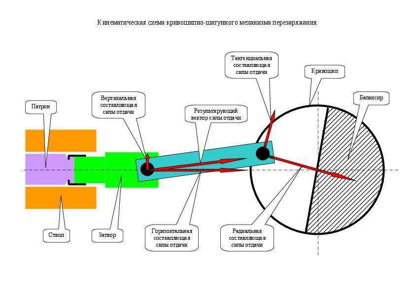
The horizontally directed recoil force acting along the axis of the barrel is converted by the connecting rod into a vertical component acting on the guides of the receiver and into the resultant vector transmitted along the axis of symmetry of the connecting rod to the neck of the cranks. At this point, the resulting vector is transformed into a tangential component of the recoil force (generating torque of the cranks) and the radial component of the recoil force (generating the support reaction). The rotational speed of the cranks varies sinusoidally with the first maximum reaching the top dead center and the second maximum (the value of which is less than the first maximum taking into account the energy consumption for compressing the return spring) at the bottom dead center. The speed of the reciprocating motion of the shutter also varies sinusoidally with a shift of the highs and lows by 90 degrees.
At the bottom dead center of rotation of the cranks, unstressed stop and reversal of the movement of the shutter against the background of continuing rotation of the crank in a given direction, followed by acceleration of all moving elements of the reloading mechanism due to recharge energy from the expanding return spring occur. On the approach to the top dead center, the shutter speed slows down to almost zero, followed by its movement reversing due to the pressure of the powder gases from the combustion of the propellant charge of the cartridge. This also reverses the rotation of the crank. In the event of a misfire of the cartridge, the bolt rests against the breech slice, supported by a return spring. The stop point of the bolt into the barrel corresponds to the 1 degree of underdrive of the cranks to the top dead center. Turnover cranks between points 5 and 1 degrees corresponds to the time of combustion of the propellant charge of the cartridge. In this regard, the shot is made with the shutter almost stopped and the cranks continue to roll out.
In order to implement a balanced automation scheme, the effective diameter of the cranks, equal to twice the distance from the axis of the neck to the axis of rotation of the cranks, must coincide with the working stroke of the shutter between the front and rear end positions. The weight of the crank balancers must correspond to the total mass of the bolt with the connecting rod, corrected for the distance of the center of mass of the balancers from the axis of rotation of the cranks. Only in this case will the movement of the weapon's center of gravity be fully compensated during the operation of the reloading mechanism.
However, these linear dimensions and the mass of moving parts, sufficient for perceiving loads from the recoil force and ensuring the balance of automation, are unacceptable for the case of handguns, since the amount of torque transmitted from the semi-free valve to the cranks causes a shooting rate of several thousand rounds per minute . Reducing the rate of fire to the standard level in 600 rounds per minute will require a multiple increase in weight and / or linear dimensions of the moving parts. In addition, cyclical reversal of cranks rotating in one direction, on the way to the top dead center, leads to the emergence of a reactive moment alternately flipping / tilting a weapon.
The Yurchenko automation system requires substantial revision in order to be used in handguns. The most obvious solution is to switch from two cranks rotating in one direction to two cranks rotating in different directions. In the latter case, the reactive moments arising from the reversal of rotation, will mutually compensate each other. A more nontrivial solution is a method of reducing the torque applied to the cranks during the combustion process of the propellant charge of the cartridge, which is a fundamental point in the matter of using a crank mechanism in a handgun. As such, it is proposed to use the opportunity created by the kinematics of the crank mechanism itself, namely by slowing down to almost zero the rate of translational movement of the shutter when it approaches the top dead center.
In order to realize this possibility, it is necessary to divide the bolt into the stem and bolt carrier. The stem should be made in the form of a free gate (hereinafter referred to as a shutter), slowed down only by the inertia of its mass and the strength of the buffer spring resting on the bolt carrier. In turn, the slide frame at the approach to the top dead center will be slowed down by a crank mechanism according to its kinematics. The pressure of the powder gases will act on the gate, overcoming its inertia and the elastic force of the buffer spring. A pressure not exceeding the rigidity of the buffer spring in compression will be transmitted to the gate frame, up to the stop of the gate face in the gate frame. The mass of the moving elements and the degree of elasticity of the buffer spring should provide a distance in time of the moment of emphasis by an amount sufficient for the peak of the pressure of the powder gases in the barrel to decrease, thereby reducing the amount of torque applied to the cranks. Based on the maximum pressure in the barrel in 4000 bar and maximum recoil force in 2880 kgf, you can estimate the total mass of the bolt in 50 grams with the maximum spring elasticity in 1000 kgf. The stroke of the shutter will be about 5 mm. Removing the load from the buffer spring will occur under conditions of backpressure of the powder gases, so the force of the blow backward impact on the bolt carrier will not exceed the tensile strength of their structural material.
However, the final decision can only be considered a transition to a new type of unitary cartridge, designed to roll back at the peak pressure of powder gases. The cartridge case must be cylindrical in shape to eliminate the danger of detachment of a Dult or skate. To connect the bullet and the liner it is necessary to use a piece of pressed propellant with an open end. As a structural material of the sleeve, an antifriction material should be used, which multiply reduces the coefficient of friction of the sleeve against the barrel chamber compared to brass or steel.
In connection with the above, an innovative project of the “weapon / cartridge” complex under the title GX-6 is proposed. The complex includes an assault rifle and a low-pulse cartridge to it. A magazine with cartridges is placed on top along the barrel. The cartridges in the store are staggered in an upright position, with bullets pointing upwards and rebuilding one row at the exit of the store.
The assault rifle is made according to the bullpup scheme in order to accommodate the overall elements of the reloading mechanism in the butt. The basis of the layout of the crank mechanism is the receiver, connected by a threaded connection with the barrel. In the body of the box there are seats for cranks and guides for the shutter. The barrel has a return thread and an axial stop located in the breech. The barrel and receiver are hung relative to the body of the weapon, connecting with it in the area of the neck of the butt.
The cranks are made in the form of metal cups of small height, in one half of which there are removable fingers for fastening the connecting rods, in the other half there are balancers. The side walls of the glasses serve as an inner sleeve bearing housing. The cranks are installed with a fit in the annular projections of the receiver, which serve as the outer sleeves of the bearings. Each crank connects to its connecting rod. The other side of the connecting rods are attached to the fixed fingers, located on the shank of the bolt carrier.
A clutch is placed in the front end of the bolt box, inside of which is applied the upper and lower sectors of the screw thread with two smooth sections between them. On both sides of the coupling there are also openings for the passage of the pushers supported on the slide frame. Folding handles of manual reloading of the weapon are mounted on opposite ends of the pushers; they are pressed by their own compression springs to the body of the weapon in order to avoid spontaneous movement during firing. To ensure the opposite rotation of the cranks after they stand in the bottom dead center, the length of the pushers is chosen less than the length of the working stroke of the slide frame. On each side wall of the box, between the coupling and the crank bore, there passes a pair of knife guides of the slide frame, simultaneously acting as stiffeners. The guides are spaced in height by the diameter of one of the two return springs located between them.
The bolt carrier in the plan has a T-shape and is made of a solid metal billet by milling. The shoulders of the bolt carrier rests on the return spring, the side surfaces in contact with the guides of the receiver. At the front end of the frame there is a hole for the bolt, at the rear end there is a hole for the drummer. On the side surfaces of the shank are fixed removable connecting rod fingers. The front of the upper surface of the frame has a bevel facing the trunk.
The shutter is made in the form of a stem, the back of which is immersed in the body of the bolt carrier, the front part is equipped with two horizontal extractors. At the rear end of the shutter there is an annular protrusion, limiting the movement of the shutter inside the frame. Between the annular protrusion and the rear wall of the frame there is a buffer spring in the form of an assembly of cup springs made of a titanium spring alloy, which has a threefold load capacity compared to the steel equivalent. Inside the gate there is an inertial hammer with its compression spring, which is activated by means of a trigger of a firing mechanism.
The crank mechanism is assembled in the following order. In the factory, they connect the bolt carrier with the bolt, buffer spring, hammer, and hammer spring, and also install the cranks into the seats of the receiver. Then put the rods on the fingers of the shank of the frame. Return springs are placed between the guides of the receiver. Through the sleeve coupling into the box enter the bolt carrier with rods. The opposite ends of the connecting rods connect removable fingers with cranks.
Submission of cartridges to the line of filing and removal of spent cartridges is carried out in the direction from top to bottom. The open end of the store rests on the retainer located next to the telescopic cartridge feeder, hinged above the bolt carrier. The free end of the feeder is equipped with horizontal grippers that fit into the groove of the cartridge case located at the outlet of the magazine. Inside the feeder is placed a coil spring, which ensures the separation of parts of its telescopic body. The hinge suspension and feeder grips are equipped with torsion springs, which provide deflection of the suspension and clamps at an angle of 45 degrees in the direction of, respectively, back and forth.
In the extreme forward position, the bolt carrier, with its bevel on the upper surface, presses the feeder up to the stop. After the frame rolls back to the rearmost position, the coil spring pushes the two parts of the telescopic feeder, thus reflecting the gun case down. The torsion springs unfold the body and the grippers of the feeder to the position of withdrawal of the cartridge to the disassembly line. During the reverse movement of the bolt carrier, vertical extractors of the bolt enter the groove of the cartridge case, move the horizontal grippers of the feeder apart and send the cartridge into the barrel. Shutter extractors provide constant clamping of the bottom of the sleeve to the mirror of the shutter until its reflection at the end of the cycle of reloading the weapon.
The body of the assault rifle consists of a casing and a rubber butt pad. The casing is made of glass-filled polymer. In front of the casing in two tiers there are spaces for placing a translucent magazine and a barrel, on the side surfaces of which cuts are made, respectively, to control the presence of cartridges in the magazine and to cool the barrel. Between the tiers on the side surfaces of the casing there are two guides for the magazine. The front and rear ends of the housing are open. In the middle part of the casing there is a pistol type control handle. In the lower part of the butt there is an ejector hole to remove the spent cartridges and the axial cartridges. The ejector hole is closed by a protective curtain that opens when the bolt carrier rolls back. Metal Picatinny trims are mounted on the rivets above and below in the front part of the casing. They are intended for fastening including mechanical and optical sighting devices.
The modular firing mechanism is located inside the control handle and includes a guard, trigger, double-sided fuse / firing mode selector and two longitudinal thrusts, which set the trigger in motion, installed separately under the receiver.
The following metal embedded parts are mounted inside the casing:
- sleeve mounting stem and receiver;
- sleeve mounting the muffler with internal sector thread;
- strap attachment trigger;
- bearing strips for manual reload handles pushers;
- strap fastening latch store and telescopic feeder cartridges;
- a level of fastening of a cock and a protective curtain.
Assembling an assault rifle is performed in the following sequence. At the beginning of the inside of the casing, the firing mechanism, cartridge feeder, trigger and protective curtain are installed. Then, the receiver and the barrel are inserted into the casing from the front and rear, which come together while simultaneously supporting the ends of the box coupling and the axial support of the barrel into the mounting sleeve. In conclusion, a rubber butt plate rests elastically in the rear end of the casing, resting on the receiver box. As a result of the direct transfer of the stop of the receiver through the butt plate into the shoulder of the shooter, the non-metallic casing is completely removed from the compressive load of the recoil force. When firing without stopping the butt into the shoulder, the case experiences a tensile load in a small area from the back side of the control handle to the point of the trunk stop in the attachment sleeve to the weapon body.
The prerequisite for the transition to a new type of ammunition, optimized for semi-free shutter automation systems, is the emergence of modern construction materials suitable for the manufacture of a nonmetallic sleeve of the unitary cartridge instead of its manufacture from traditional brass and steel.
The sleeve in the cartridge performs several functions:
- ensuring the mechanical strength of the cartridge during operation
- accumulation of heat transferred from the barrel to the cartridge;
- obturation of powder gases when fired.
The rejection of casings and the transition to caseless cartridges leads to a decrease in the thermal barrier of their spontaneous combustion in the barrel to the level of the flash point of the propellant charge, which will always be achieved when conducting intensive automatic fire, an example of which is the Heckler & Koch G11 serial assault rifle.
The use of standard sleeve cartridges in combination with Revelli grooves applied to the barrel chamber surface and designed to reduce friction of the sleeve, in the case of a semi-free valve, leads to an increased gas content of the receiver and unstable operation of the reloading mechanism due to the settling of powder burning on the contact surfaces of moving parts, which It was demonstrated on the example of an experienced manual machine gun Degtyarev-Garanin KB-P-790.
In connection with the above, the innovative cartridge cartridge is proposed to use a carbon-carbon composite obtained by burning a structural foam and pressing it into a billet of a cylindrical sleeve, the fine pores of which are impregnated with a high-molecular silicone resin by sintering. The composite material obtained has a strength at the level of brass and a friction coefficient at the level of graphite, i.e. 3,5 times smaller compared to the friction coefficient of brass. The weight of the composite liner is also reduced several times compared to the metal.

The sleeve has a strictly cylindrical shape with a spherical inner bottom surface, selected from the point of view of excluding stress concentrations in its structure. The diameter of the sleeve welt is less than the diameter of the wall for the thickness of the gate extractors. The bullet of the ogival shape is connected to the sleeve by pressing a propellant charge into the checker, immersed in the sleeve to the level of the edge. The open end of the propellant is coated with nitro lacquer. In the bottom of the liner there is a seat for the primer. In the body of the checker, a flare channel passes from the capsule to the bullet, at the end of which there is an additional accelerator charge, which pushes the bullet out of the checker until the main propellant ignites. As a propellant charge can be used as a nitrocellulose powder and phlegmatized HMX applied in cartridges to the machine gun LSAT, equipped with a plastic sleeve.
The cartridges are loaded into the magazine, the length of which is equal to the length of the rifle barrel. After loading into a weapon the shop does not go beyond the dimensions of the body of the rifle. Spare stores are carried in the shoulder pack,
Tactical and technical characteristics of the assault rifle and ammunition project GX-6:
Caliber - 5,56x35 mm
Sleeve diameter - mm 11,8
Sleeve length - 35 mm
Cartridge length - 50 mm
The weight of one cartridge - 7 grams, including bullet - 4 grams, propellant charge - 2 grams, sleeves - 1 grams
Number of cartridges in the shop - 60 units
Shop weight with cartridges - 700 grams
Weight of a rifle without a magazine - 3000 grams
Firing Rate - 800 shots per minute
Initial bullet speed - 950 m / s
Muzzle Energy - 1800 J
Maximum chamber pressure - 4000 bar
Rifle length - 758 mm
Height - 240 mm
Width - 40 mm
Sighting line length - 400 mm
The distance from the sighting line to the axis of the barrel - 100 mm
Barrel length - 508 mm
Barrel chamber length - 51 mm
Spinning flame arrestor length - mm 48
Butt plate thickness - 20 mm
Jacket Length - 690 mm
Housing shell thickness - 2 mm
The length of the receiver - 220 mm
The thickness of the side wall of the receiver - 3 mm
Return spring diameter - 15 mm (total two units)
Return spring length - 100 mm
Crank Diameter - mm 80
Slide frame length with shutter - 60 mm, including 20 shank mm, 10 shutter mm
Slide frame stroke - 60 mm
Connecting rod length - 80 mm (only two units)
The diameter of the fingers of the rods - mm 10
Gate frame weight assembly with gate and buffer spring - 150 grams
Rod weight - 50 grams
Crank case weight - 50 grams (total 2 units)
Balance weight - 250 grams (total 2 units)
Total weight of the moving parts of the reloading mechanism - 850 grams
The project of the GX-6 complex has an inventive level of technical solutions and is intended for patenting within six months from the date of this publication. In this regard, investors from the number of licensed manufacturers of weapons and ammunition are invited to participate in the project.
Information sources:
Firing tables at ground targets from small arms caliber 5,45 and 7,62 mm. TS GRAU N 61 edition 1977 of the year http://www.ak-info.ru/joomla/index.php/uses/12-spravka/92-shttables77
D.Shiryaev. Record holder. "Weapon" No. 1 for 2007 year http://zonawar.narod.ru/or_2007.html
Patent RU 2193542 http://ru-patent.info/21/90-94/2193542.html
Information