The world's first underwater mine layer "CRAB" (part 1)

The creation of the world's first underwater mine layer "Crab" is one of the wonderful pages in stories Russian military shipbuilding. The technical backwardness of Tsarist Russia and an entirely new type of submarine, such as the Crab, led to the fact that this minelayer entered service only in 1915. But even in such a technically developed country, which was Kaiser Germany, the first submarine minelayers appeared only in the same year, moreover, in their tactical and technical data, they were significantly inferior to the "Crab".
MICHAEL PETROVICH NALETOV
Mikhail Petrovich Naletov was born in 1869 in the family of the Caucasus and Mercury shipping company. His childhood years were spent in Astrakhan, and he received his secondary education in St. Petersburg. Upon completion of secondary education, Mikhail Petrovich entered the Technological Institute, and then moved to the Mining Institute in St. Petersburg. Here he had to learn and earn a living with lessons and drawings. In his student years, he invented a bicycle of the original design, to increase the speed of which it was necessary to work with both hands and feet. At one time, these bicycles produced a handicraft workshop.
Unfortunately, the death of his father and the need to support his family - his mother and young brother - did not allow Naletov to graduate and get a higher education. Subsequently, he passed the exams for the title of technician of communications. MPNaletov was a very sociable and kind person, with a gentle nature.
In the period preceding the Russian-Japanese war, Naletov worked on the construction of the port of Dalniy. After the start of the war, MP Naletov was in Port Arthur. He witnessed the death of the battleship "Petropavlovsk", in which the famous admiral SO Makarov was killed. The death of Makarov led Naletova to the idea of creating an underwater mine layer.
At the beginning of May 1904, he appealed to the port commander Port Arthur with a request to give him a gasoline engine for the submarine being built, but he was refused. According to Naletova, sailors and conductors from the squadron ships were interested in the submarine under construction. They often came to him and even asked to write him to the submarine team. Great help to Naletov was provided by Lieutenant N.V. Krotkov and mechanical engineer from the battleship Peresvet P.N.Tihobaev. The first helped get the necessary mechanisms for the submarines from the Dalniy port, and the second let out specialists from their team, who together with the workers of the dredging caravan worked on the construction of the minelayer. Despite all the difficulties, Naletov successfully built his submarine.
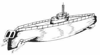
The submarine body was a riveted cylinder with conical extremities. Inside the hull there were two cylindrical ballast tanks. The displacement of the haul was only 25 t. He was to be armed with four mines or two torpedoes Schwarzkopf. Mines were supposed to put through a special hatch in the middle of the hull of the boat "by itself". In subsequent projects, Naletov refused such a system, believing that it was very dangerous for the submarine itself. This fair conclusion was later confirmed in practice - German underwater minelayers like "UC" became victims of their own mines.
In the autumn of 1904, the construction of the haulier’s hull was completed, and Naletov began to test the strength and watertightness of the hull. For immersion of the boat on the spot without people, he used cast iron pigs, which were placed on the submarine deck, and were removed using a floating crane. The barrier was plunged to a depth of 9 m. All tests were normal. Already during the tests, the submarine commander, midshipman B.A. Vilkitsky, was appointed.
After successful tests of the hull of the submarine, the attitude towards Naletov changed for the better. He was allowed to take a gasoline engine for his submarine from the boat of the battleship Peresvet. But this "gift" put the inventor in a difficult position, because power of one motor was insufficient for the submarine under construction.
However, the days of Port Arthur were already numbered. Japanese troops came close to the fortress and the shells of their artillery fell into the harbor. One of these shells sank the iron barge, to which the landlayer Naletova was moored. Fortunately, the length of the mooring lines was sufficient and the minelayer remained afloat.
Before the surrender of Port-Arthur in December 1904, Mr. MP Naletov, in order to prevent the minelayer from falling into the hands of the Japanese, he was forced to disassemble and destroy his internal equipment, and to blow up the hull itself.
For active participation in the defense of Port Arthur Naletov was awarded the Cross of St. George.
The failure of the construction of an underwater mine layer in Port Arthur did not discourage Naletova. Arriving after the surrender of Port Arthur to Shanghai, Mikhail Petrovich wrote a statement proposing to build a submarine in Vladivostok. The Russian military attache in China sent Naletov’s statement to the naval command in Vladivostok. But it did not find it necessary to even reply to Naletov, believing, obviously, that his proposal was one of those fantastic inventions that should not be paid attention to.
But this was not Mikhail Petrovich to give up. Upon his return to St. Petersburg, he developed a new project of an underwater mine layer already with a displacement of 300 and.

29 December 1906 Mr. Naletov submitted a petition addressed to the Chairman of the Marine Technical Committee (MTC), in which he wrote: "Wishing to offer the Marine Ministry the submarine on the project I developed based on the experience and personal observations of the maritime war in Port Arthur, I have the honor to ask your excellency, if you find it possible, to set me a time in which I could personally present the above-mentioned project and give an explanation to his persons, your excellency authorized. "
Attached to the petition was a copy of the 23 certificate of February 1905 issued by the former Port Arthur commander Rear Admiral IK Grigorovich (later the Minister of the Navy), who said that the submarine of 25 t in displacement was built in Port Arthur gave excellent results in preliminary tests "and that the surrender of Port Arthur made it impossible for Naletova’s technician to complete the construction of the boat, which would bring the besieged Port Arthur great benefit." Mikhail Petrovich considered his port-artur project as year project minelayers.
In 1908-1914, Naletov visited Nizhny Novgorod several times when the whole Zolotnitsky family lived at a dacha in the town of Mokhovye Mountains on the banks of the Volga, 9 km from Nizhny Novgorod. There he made a toy - cigar-shaped, similar to the modern submarine 30 cm long with a small tower and a short rod ("periscope"). Submarine moved under the action of a wound spring. When the submarine was allowed into the water, it sailed about five meters on the surface, then plunged and floated five meters under water, setting only its periscope, then re-emerging to the surface, and the diving alternated until the entire plant went out. The submarine had a hermetic enclosure. As you can see, even making toys, Mikhail Petrovich Naletov was fond of the PL ...
NEW PROJECT OF THE UNDERWATER MINING PLAYER
After the defeat in the Russo-Japanese War, the Ministry of the Sea took up preparations for the construction of a new fleet. The discussion developed: what fleet does Russia need? The question also arose about how to get loans for the construction of the fleet through the State Duma.
With the beginning of the Russian-Japanese war, the Russian fleet began to replenish the submarine intensively, some of them were built in Russia, and some were ordered and bought abroad.
In 1904 - 1905 24 PLs were ordered and 3 ready-made PLs purchased abroad.
After the end of the war, in 1906, they ordered only 2 PL, and in the next, 1907, none! This number did not include the submarine SK Dzhevetskogo with a single engine "Postal".
Thus, due to the end of the war, the tsarist government lost interest in the submarine. Many officers in the high command of the fleet underestimated their role, and the liner was considered to be the cornerstone of the new shipbuilding program. The construction experience of M.P. Naletov in Port Arthur of the first minelayer was naturally forgotten. Even in the maritime literature it was stated that "the only thing the submarines can be armed with are self-moving mines (torpedoes)."
Under these conditions, it was necessary to have a clear mind and clearly understand the prospects for the development of the fleet, in particular, its new formidable weapons - Submarine, to propose the construction of an underwater mine layer. Such a person was Mikhail Petrovich Naletov.
Having learned that “the Naval Ministry does nothing to create this new type of warship, despite the fact that its main idea became well-known, MP Naletov 29 of December 1906 submitted a petition to the Chairman of the Marine Technical Committee (ITC), in which he wrote: “Wishing to propose the Marine Ministry of the submarine for the project I developed based on the experience and personal observations of the maritime war in Port Arthur, I have the honor to ask Your Excellency, if you find it possible, to assign me time in which
Personally present the aforementioned project and give an explanation to its persons, Your Excellency authorized to do so. "
Attached to the petition was a copy of the 23 certificate of February 1905 issued by the former Port Arthur commander, Rear Admiral IK Grigorovich (later Navy Minister), which stated that the submarine built in Port Arthur’s displacement in 25 was excellent results on preliminary tests "and that" the surrender of Port Arthur made it impossible for Naletov to complete the construction of the submarine, which would bring great benefit to the besieged Port Arthur. "
MP Naletov considered his port-arthur submarine as a prototype of a new project of an underwater mine layer.
Considering that the two shortcomings inherent in the submarines of that time — a low speed and a small navigation area — will not be eliminated in the near future at the same time, Mikhail Petrovich examines two submarine options: with high speed and a small navigation area and with a large navigation area and a small speed.
In the first case, the submarine must "wait for the enemy ship to approach the port, near which the submarine is located."
In the second case, the submarine task consists of two parts:
1) go to the enemy port;
2) blasting enemy ships "
MP Naletov wrote: "Without denying the benefits of the submarine in coastal defense, I find that the submarine mainly has to be an instrument of offensive war, and for this it must have a large area of operation and is armed not only with Whitehead mines, but mine barriers in other words, apart from submarine destroyers of coastal defense, submarine destroyers and minelayers of a large area of action need to be built. "
For that time, these views of MP Naletov on the development prospects of submarines were very progressive. The statements of Lieutenant A.D. Bubnov should be cited: "Submarines are nothing but mine banks!" And further: "Submarines are a means of passive positional warfare and, as such, cannot decide the fate of war."
How much in terms of scuba diving, the technician of communications M.P. Naletov stood above the naval officer Bubnov!
He rightly pointed out that "an underwater mine layer, like any submarine, does not need to possess ... the sea." A few years later, during the First World War, this statement of Naletova was fully confirmed.
Speaking of the fact that Russia is not able to build a fleet equal to that of Britain, MP Naletov stressed the special importance for Russia of building submarines: "50 underwater mine-layer barriers in 300 tons each will be able to deliver monthly from 3 to 5 thousands of mines, the number with which it is hardly possible to fight, and this will cause the utmost halt to the marine life of the country, without which England and even Japan will not survive for long.
What was the project of the underwater mine layer presented by M, P. Naletov at the end of 1906.
Displacement - 300 t, length - 27,7 m, width - 4,6 m, draft - 3,66 m, buoyancy margin - 12 t (4%).
The barrier should be installed for the 2 motor's 150 motor surface stroke. each, and for underwater running - 2 electric motor for 75 hp They were supposed to provide submarine surface speed of 9 nodes, submerged - 7 nodes.
The minelayer was supposed to take on board the 28 mines with one torpedo tube and two torpedoes or 35 mines without a torpedo tube.
Depth depth immersion - 30,5 m.
The body of the submarine is cigar-shaped, the cross section is a circle. The superstructure began with the nose of the submarine and extended the distance from 2 / 3 to 3 / 4 of its length.
"When a round section of the case:
1) its surface will be the smallest with the same cross-sectional area of the frames;
2) the weight of the round frame will be less than the weight of the frame of the same strength, but of a different cross-sectional shape of the submarine, whose area is equal to the area of the circle;
3) the case will have a smaller surface and the least weight, of course. When comparing submarines having the same drill on the frames ".
Any of the elements chosen by him for his project, Naletov tried to substantiate, relying on the theoretical studies that existed at that time or by logical reasoning.
MPNaletov came to the idea that the superstructure should be asymmetric. The inside of the raid superstructure was supposed to be filled with cork or some other light material, and he proposed to make scuppers in the superstructure, through which water would pass freely between the cork layers and the submarine body, which transferred pressure to the strong submarine body inside the superstructure.
The main ballast tank submarine with a displacement of 300 t of the Naletovo project was located under the batteries and in the side tubes (high-pressure tanks). Their volume was 11,76 cube. m. In the extremities of the submarine were differential tanks. Mine-replacement tanks with a volume of 11,45 cube were located between the mine storage room in the middle part and the submarine sides. m
The device for setting mines (in the project it was called the “mines throwing machine”) consisted of three parts: a mine tube (in the first version of one), a mine chamber and an air lock.
The mine tube went from the bulkhead of the 34 th frame obliquely to the stern and exited the submarine hull outside under the lower part of the vertical rudder. At the top of the pipe was a rail, along which the mines were rolling with the help of rollers in the stern, due to the inclination of the pipe. The rail went along the entire length of the pipe and ended at the same level as the steering wheel, and from the sides of the rail at the time of the laying of mines, special guides were exposed to give the mines the right direction. The nasal end of the mine tube entered the mine chamber, where 2 people received mines through the airlock and put them into the mine tube.
To prevent the ingress of water into the submarine through the mine pipe and mine chamber they let in compressed air, balancing the pressure of seawater. The pressure of the compressed air in the mine tube was regulated by an electric contactor.
The mines are stored by MP Naletov in the middle part of the submarine between the diametral plane and the onboard minesubstituting cisterns, and in the fore part - along the sides of the submarine. Since they maintained normal air pressure, between them and the mine chamber there was an air lock with hermetic doors both in the mine chamber and in the mine storage. The mine tube had a lid, which, after setting the mine, was hermetically sealed. In addition, for laying mines on the surface, the Raids proposed to make a special device on the submarine deck, the device of which remained unknown.

As can be seen from this brief description, the initial device for setting mines did not fully provide the submarine with equilibrium when setting mines in the submerged position. Thus, the extraction of water from the mine pipe was made overboard, and not into a special tank; A mine that was still moving along the upper rail before being immersed in water at the end of the mine tube disrupted the submarine balance. Naturally, such a device for setting mines for an underwater mine layer was not suitable.
The torpedo armament of the underwater layer Zaletov provided in two versions: with one TA and 28 mines and without TA, but with 35 mines.
He himself gave preference to the second option, considering that the main and only task of the underwater minelayer is the laying of mines, and everything should be subordinated to this task. The presence of a torpedo arrestor can only prevent him from accomplishing the main task: safely deliver the mines to the place of their production and successfully expose the production itself.
9 January 1907 was held in MTC the first meeting was held to review the draft of the underwater mine layer proposed by M.P. Naletov. The meeting took place under the chairmanship of Rear Admiral A. Vienius with the participation of outstanding shipbuilders AN Krylov and IG Bubnov, as well as the most prominent mineral and submariner M. N. Beklemishev. The Chairman briefed those present with the proposal by M.P. Naletova. The raids also outlined the main ideas of their project of an underwater mine layer with a displacement of 300 tons. After an exchange of views, it was decided to consider in detail and discuss the draft at the next meeting of the ITC, held on January 10. At this meeting, Naletov described in detail the essence of his project and answered the numerous questions of those present.
From the speeches at the meeting and the subsequent comments of specialists on the project:
"The project of the submarine of Mr. Naletov is quite feasible, although not fully developed" (ship engineer I.A. Gavrilov).
“Mr. Naletov’s calculations were made quite correctly, in detail and in detail” (A.N. Krylov).
However, the project’s drawbacks were noted:
1. Small reserve of buoyancy of the submarine, which M.N.Beklemishev paid attention to.
2. Filling the add-in with a stopper is impractical. As A.N.Krylov pointed out: "Squeezing a cork by water pressure changes buoyancy in a dangerous direction as it dives."
3. The dive time of the submarine - more than 10 minutes - is too long.
4. There is no periscope on the submarine.
5. Devices for mine "little satisfactory" (IG Bubnov), and the time of setting each mine - 2 - 3 minutes - is too long.
6. The power of motors and electric motors specified in the project cannot provide the specified speeds. "It is unlikely that the submarine in 300 t will take place at 150 hp - 7 nodes and on the surface at 300 hp - 9 nodes" (I.A. Gavrilov).
A number of other, smaller, deficiencies were noted. But the recognition by prominent specialists of that time of the project of the underwater mine layer “quite feasible” is undoubtedly the creative victory of MP Naletov.
1 January 1907 Mr. Naletov has already submitted to the Chief Inspector of the Mines: 1) "Description
advanced mine-mines for the ejection of sea mines "and 2)" Description of the modification of the superstructure. "
In the new version of the device for setting mines, Mikhail Petrovich provided for a “two-stage system”, i.e. mine pipe and airlock (without a mine chamber, as it was in the original version). The air shutter was separated from the mine tube by a hermetically sealed lid. When putting mines in the “combat” or positional position of the submarine, compressed air was supplied to the mine compartment, the pressure of which was to balance the external pressure of the water through the mine tube. After that, both air-blin covers and mines opened along the rail at the top of the pipe, one by one they were thrown overboard. When setting the mine in the underwater position, when the back cover is closed, the mine was introduced into the airlock. Then the front cover was closed, compressed air was let in to the airlock to the pressure of the water in the mine pipe, the back cover was opened, and the mine was thrown over the pipe. After that, the back cover was closed, the compressed air was removed from the airlock, the front cover was opened, and a new mine was introduced into the airlock. This cycle was repeated again. The raids indicated that new mines with negative buoyancy were required for staging. When mined, the submarine received trim aft. Later, the author took into account this shortcoming. The time of setting mines decreased to one minute.

A.N. Krylov wrote in his review: "The way of setting mines cannot be considered finally developed. It is desirable to further simplify and improve them."
IG Bubnov, in his review from January 11, wrote: "It is rather difficult to regulate the buoyancy of the submarines with such significant weight changes, especially at a fluctuating level in the pipe."
While working on improving his mine-laying machine, Naletov already in April 1907 proposed a "mine barrage with a hollow anchor, the negative buoyancy of which was equal to the positive buoyancy of the mine." This was a decisive step towards the creation of a mine-setting apparatus suitable for installation on an underwater minelayer.
Interesting is the classification of "devices for throwing mines out of submarines," given by Naletov in one of his notes. All the "devices" Mikhail Petrovich was divided into internal, located inside the strong submarine hull, and external, located in the superstructure. In turn, these devices were divided into feed and non-feed. In the outer side (non-feed) apparatus, mines were located in special sockets in the sides of the superstructure, from which they were to be ejected one by one with the help of levers connected with a roller running along the superstructure. The roller was set in motion by turning the handle from the wheelhouse. In principle, such a system was later implemented on two French submarines built during the First World War and later converted into submarine barriers. Mines were in the onboard ballast tanks in the middle of these submarines.
The external feeding apparatus consisted of one or two troughs that ran along the boat in the superstructure. Mines moved along the rail laid in the trench with the help of four rollers attached to the sides of mine anchors. There was an endless chain or cable along the bottom of the trench to which mines were attached in various ways. The chain moved as the pulley rotated from the inside of the submarine. This system of mine raids came, as will be shown, in its subsequent versions of the underwater mine layer.
The internal bottom (non-feed) apparatus consisted of a cylinder mounted vertically and connected on one side to the mine chamber, and on the other hand through an opening in the bottom of the submarine hull with outboard water. This principle of the apparatus for setting mines Naletov used, as is well known, for an underwater layer, built by him in Port Arthur in 1904.
The internal feeding apparatus was to consist of a pipe connecting the mine chamber with the outside water in the lower part of the submarine stern.
Considering the possible options for setting mines, MP Naletov gave a negative characteristic to bottom-mounted vehicles: he pointed out the danger to the submarine itself when laying mines from such devices. This conclusion Naletova relatively bottom apparatus was fair for its time. Much later, during the First World War, the Italians used a similar method for their underwater mine layers. Mines were in Miino-ballast tanks located in the middle part of the submarine's robust hull. In this case, the mines had a negative buoyancy of the order of 250-300 kg.
To improve the ventilation of the submarine, a ventilation pipe with a diameter of about 0,6 m and a height of 3,5 - 4,5 m was proposed. Before the dive, this pipe was folded into a special recess of the superstructure deck.
6 February in response to the request of M.N. Beklemisheva A.N.Krylov wrote: “Increasing the height of the superstructure will help to improve the submarine seaworthiness in its surface voyage, but with the proposed height it will hardly be possible to go with an open deck when the wind and the wave will be over 4 points ... It is necessary to expect that the submarine will be so buried in the wave that it will be impossible to keep the wheelhouse open. "
SECOND AND THIRD MODES OF THE UNDERWATER PLOT
After the MTC chose the system of “fodder external devices”, MP Naletov, taking into account the comments of the committee members, developed the second version of the underwater mine layer with a displacement of 450 t. The submarine length in this variant increased to 45,7 and the surface velocity increased to 10 nodes, and the navigation area at this speed reached 3500 miles (instead of 3000 miles in the first embodiment). Diving speed - 6 nodes (instead of 7 nodes according to the first option).
With two mine tubes, the number of mines with the “anchor of the Naletovo system” was increased to 60, but the number of torpedo tubes was reduced to one. The time it takes to mine one mine is 5 seconds. If in the first variant 2 - 3 minutes was required for setting one mine, then this could already be considered a great achievement. The height of the cabin hatch above the waterline was about 2,5 m, the reserve of buoyancy - about 100 t (or 22%). True, the transition time from the surface to the underwater position was still quite significant - 10,5 minutes.
On May 1, 1907, acting as Chairman of the ITC, Rear Admiral A.A. Virenius and so on. The Chief Inspector of the mine case, Rear Admiral Mikhail F. Loschinsky, a special report addressed to the Deputy Minister of Navy for the mine-laying project MP Naletov wrote that the MTC "on the basis of preliminary calculations and verification of the Drawings found it possible to recognize the project as feasible."
Further, the report proposed "as soon as possible" to enter into an agreement with the head of the Nikolaev shipbuilding plants (more precisely, the Society of shipbuilding, mechanical and foundry plants in the city of Nikolaev), which, as reported by 29 March 1907, gave "the exclusive right to build underwater minelayers "of his system, or enter into an agreement with the head of the Baltic plant, if this recognizes the useful maritime minister.
And finally, the report said: "... it is necessary to simultaneously attend to the development of special mines, at least for the project of Captain 2 of Schreiber's rank."
The latter is clearly puzzling: after all, MP Naletov presented not only the project of the minelayer as a submarine, but also mines with a special anchor for him. So where does the captain of 2 rank Schreiber come in?
Nikolai Nikolayevich Schreiber was one of the prominent specialists of his time in the mine business. At the end of the Naval Cadet Corps and then the mine officer class, he sailed mainly on ships of the Black Sea Fleet as a mine officer. In 1904, he served as the chief mineral worker at Port Arthur, and during the period from 1908 to 1911, he served as an assistant to the chief mine inspector. Apparently, under the influence of MP Naletov's invention, he, together with the ship’s engineer IG Bubnov and Lieutenant S. Vlashev, began developing mines for an underwater mine layer using the principle of zero buoyancy, i.e. the same principle that applied to their mines MPPaletov. For several months, until MP.Naletov was suspended from building a minelayer, Schreiber sought to prove that neither the mines, nor the system of their production from the minelayer, developed by Naletov, are worthless. Sometimes his struggle against Naletova was in the nature of petty quibbles, sometimes he even with malicious gloominess emphasized that the inventor of the minelayer was just a "technician."
The minister agreed with the proposals of the ITC chairman, and the head of the Baltic shipbuilding plant in St. Petersburg was given the task to develop a device for setting 20 mines with a 360 displacement tonnage under construction at this plant Akula submarine, .
Along with the device for laying mines with submarines of 360 t, built at the Baltic plant, the plant presented the 2 version of an underwater minelayer for 60 mines of the “Schreiber’s Captain 2 system” rank, with a displacement of only about 250 t, and equal to 14 nodes (!). Leaving on the conscience of the Baltiysky Zavod loyalty to the calculations of the minelayer with 60 mines and a displacement of about 250 t, we note only that two small submarine barriers launched with a displacement of about 1917 t started in 230 in only 20 minutes
At the same time, the same letter from the head of the Baltic plant at MTC 7 in May 1907 stated: “As for the number specified for MTC in 450 t (this is a variant of the project of the minelayer MP Naletov), it is absolutely not justified by the tasks and determine even approximately the cost of submarines, where almost half of the displacement is spent uselessly (?) impossible. "
Such a harsh "criticism" of the project of the minelayer in 450 t, obviously, was given by the plant not without the participation of the author of the "mine system" captain 2 of the rank of Schreiber.
Since the construction of the submarine at 360 and the Baltic Plant was delayed (the submarine was launched only in August of 1909), the preliminary testing of the device for laying mines on this submarine had to be abandoned.
Subsequently (in the same 1907), Naletov developed a new version of the minelayer underwater displacement 470 t. The surface speed of the minelayer in this variant was increased from 10 to 15 nodes, and underwater speed - from 6 to 7 nodes. The time of immersion of the haul into the positional position decreased to 5 minutes, to the underwater position - to 5,5 minutes (in the old version of 10,5 minutes).
25 June 1907 The Nikolaevsky Zavod submitted to the Chief Inspector of the Mines a draft contract for the construction of one underwater mine layer, as well as the most important data on the specifications and 2 of the sheet of drawings.
However, the Ministry of the Navy recognized that the cost of building a minelayer should be reduced. As a result of further correspondence 22 August 1907, the plant reported that he agreed to reduce the price of building one underwater layer to 1350 thousand rubles, but on condition that the displacement of the layer is increased to 500 tons.
By order of a fellow naval minister, MTC informed the plant about the ministry’s agreement with the cost of construction of the minelayer proposed in the letter of the plant from 22 in August "... because of the novelty of the case and the transfer of mines developed free of charge by the plant." At the same time, MTC asked the plant to submit detailed drawings and a draft contract as soon as possible, and indicated that the submarine’s underwater speed should not be less than an 7,5 node within 4 hours.
2 October 1907 g. The specification with the drawings and the draft contract for the construction of an "underwater mine layer system MP Naletov with a displacement of about 500 t" were presented by the plant.
THE FOURTH, THE LAST VARIANT OF THE PROGRAMMER MP NALETOV
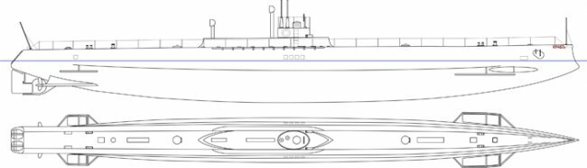
The fourth, last version of the underwater mine layer MP Naletova, adopted for the construction, was a submarine with a displacement of about 500 tons. Its length was 51,2 m, midsection width - 4,6 m, immersion depth - 45,7 m Transition time from surface position to underwater - 4 minutes. The speed in the surface position of 15 nodes with a total power of four HP 1200 motors, in a submerged position - a 7,5 node with a total power of two HP 300 electric motors. The number of electric batteries - 120. Navigation range above-water 15-nodal course 1500 miles, underwater 7,5-nodal course - 22,5 miles. 2 mine tubes are installed in the superstructure. The number of mines is 60 of the system of Naletova with zero buoyancy. The number of torpedo tubes is two with four torpedoes.
The caster of the minelayer consisted of a cigar-shaped part (durable case) with a waterproof superstructure along its entire length. To the strong case the cabin was fastened, surrounded by the bridge. The extremities were made light.
The main ballast tank was placed in the middle of a solid hull. It was bounded by a durable hull shell and two flat transverse bulkheads. Bulkheads are interconnected by horizontal pipes and anchors. There were seven total tubes connecting the bulkheads. Of these, the pipe of the largest radius (1 m) was in the upper compartment, its axis coincided with the axis of symmetry of the submarine. This pipe was used for passage from the living compartment to the engine room. The remaining pipes were of smaller diameter: two pipes by 0,17 m, two - by 0,4 m, two - by 0,7 m. Fresh air was fed from the main ventilation pipe to the living room, and four other pipes served as high-pressure ballast tanks. In addition, fore and aft ballast tanks were provided.
In addition to the main ballast tanks, there were bow and stern trim tanks, leveling tanks and torpedo replacement tanks. 60 mines were located in two mine tubes. The mines were supposed to move along rails laid in mine tubes with the help of a chain or cable device set in motion by a special electric motor. Mina with an anchor was one system and for her movement on rails served 4 roller. By adjusting the number of revolutions of the motor and changing the speed of the minelayer, thus changing the distance between the put mines.
According to the specification, the parts of the mine tubes should have been developed after the construction of the mines and testing them at a special landfill.
Specifications and drawings submitted by 2 in October 1907 were reviewed in the shipbuilding and mechanical departments of the ITC, and then on November 10 at the general meeting of the ITC chaired by Rear Admiral A.A. Virenius and with the participation of a representative of the Marine General Staff. At the meeting of MTC 30 in November, the issue of mines, engines and hydraulic testing of the minelayer body was considered.
The requirements of the shipbuilding department of the MK were as follows:
Draft of the minelayer on the surface - no more than 4,02 m.
Metacentric height in surface position (with mines) - not less than 0,254 m.
The transfer time of the vertical steering wheel - 30 with, and horizontal rudders - 20 with.
The superstructure of the barrier with closed scuppers must be waterproof.
The transition time from surface to positional position should not exceed 3,5 minutes.
The performance of air compressors should be 25000 cube. feet (708 cubic meters) of compressed air for 9 hours, i.e. during this time, a full supply of air must be renewed.
In a submerged position, the minelayer must place mines, moving at a speed of 5 nodes.
Relay speed in surface position of 15 nodes. If this speed is less than 14 nodes, then the Navy Ministry may refuse to accept the minelayer. The speed in positional position (under kerosene engines_) is 13 nodes.
The final choice of battery system must be made within the 3 month period upon signing the contract.
The haulier’s body, its ballast and kerosene tanks should be tested with an appropriate hydraulic pressure, and the water leakage should not be more than 0,1%.
All tests of the abuser must be carried out with full armament, supplies and with a fully staffed team.
According to the requirements of the mechanical department of the MTC, the 4 kerosene engine, developing at least 300 hp, should have been installed on the barrier. each at 550 rpm The system of motors should have been selected by the plant within two months after the conclusion of the contract, and the system of motors proposed by the factory was to be approved by the MTC.
After launching the Crab, MP Naletov was forced to leave the factory, and the further construction of the minelayer took place without his participation, under the supervision of a special commission of the Maritime Ministry, consisting of officers.
After the removal of Mikhail Petrovich from the construction of the Crab and the Marine Ministry and the plant, they tried in every possible way to prove that mines and a mine device, and even the barrier, are not ... "Naletov's system." 19 September 1912 held a special meeting on this subject, recorded in the minutes: “The meeting made sure that Mr. Naletov had no priority in the proposal for the submarine mine barrier with a hollow anchor (with zero or zero buoyancy mines while it is in the submarine), since this question was fundamentally developed at the mines of the MTC even before Mr. Naletov’s proposal. Therefore, there is no reason to believe that not only mines under development, but also the whole minelayer of the Naletov system ".
The creator of the world's first underwater mine layer MP Naletov lived in Leningrad. In 1934, he retired. In recent years, Mikhail Petrovich worked as a senior engineer in the department of the chief mechanic of the Kirov factory.
In the last decade of his life in free time, Naletov worked to improve underwater mine-layer barriers and filed a number of applications for new inventions in this area. N.A. Zalessky advised M.P. Naletova on hydrodynamics issues.
Despite his old age and illness, Mikhail Petrovich until the last days worked in the field of designing and improving submarine mine layers.
MP Naletov died 30 March 1938. Unfortunately, during the war and the blockade of Leningrad, all these materials died.
HOW WAS THE UNDERWATER MINING PLAYER "CRAB" WAS ESTABLISHED
The robust layer of the hawker is a cigar-shaped, geometrically regular body. The frames are made of box steel and placed at a distance of 400 mm from one another (packing), the thickness of the 12 plating is 14 mm. By the ends of the robust hull, ballast tanks were also riveted from box steel; plating thickness - 11 mm. Between 41 and 68 frames, through keel and angular steel, a keel of 16 t weight, consisting of lead plates, was bolted to a sturdy body. From the side of the landlord in the area of 14 - 115 of the frames there are "displacers" - boules.
The displacers, made of angular steel and sheathing 6 mm thick, were attached to the sturdy case with knits 4 mm thick. Four watertight bulkheads divided each displacer into 5 compartments. The lightweight superstructure with angular steel frames and sheathing 3,05 mm thick (the thickness of the superstructure deck 2 mm) was along the entire length of the patcher.
When immersed, the superstructure was filled with water, for which, in the fore, aft, and middle parts, there were so-called “doors” (valves) located on both sides, which opened from inside the robust barber’s hull.
In the middle part of the superstructure, an oval cross-section was made, made of low-magnetic steel with a thickness of 12 mm. Behind the cabin there was a breakwater.
For the dive served three ballast tanks: medium, fore and aft.
The average tank was located between the 62-m and 70-m frames of a solid hull and divided the submarine into two halves: the bow - residential and aft - machine. For communication between these rooms served as a casing pipe. The medium tank consisted of two tanks: low pressure tanks with a capacity of 26 cube. m and high-pressure tanks with a capacity of 10 cube. m
The low-pressure tank, occupying the entire sub-section of the submarine in the middle, was located between the outer skin and two flat bulkheads on the 62-m and 70-m frames. The flat bulkheads were reinforced by eight links: one flat of sheet steel (full width submarine), which was at the height of the deck, and seven cylindrical, one of which formed the flow tube for the dwelling, and the other four were high-pressure tanks.
In a low-pressure tank designed for 5 atm pressure, two Kingstones were made, the drives of which were brought into the engine room. The tank was blown with compressed air at 5 atm, coming through a bypass valve on a flat bulkhead. The filling of a low-pressure tank could be carried out by gravity, pump, or both. As a rule, the tank was blown with compressed air, but the water from it could not be pumped out and pump.
The high-pressure tank consisted of four cylindrical vessels of different diameters located symmetrically with respect to the median plane and passing through the flat bulkheads of the middle tank. Two high pressure cylinders were placed above the deck and two below the deck. The high-pressure tank served as a detachable keel, i.e. performed the same role as the detachable or medium tank on the submarine type "Leopard". It was blown with compressed air in 10 atm. The cylindrical vessels of the tank were connected by branch pipes, and each pair of these vessels had its own Kingston.
The device of the air pipeline allowed air to be introduced into each group separately, due to which it was possible to use this tank to level a significant roll. The filling of the high-pressure tank was carried out by gravity, pump, or both.
Bow ballast tank volume 10,86 cube. m was separated from the solid body by a spherical partition on the 15-m frame. The tank was designed for pressure 2 atm. Its filling was made through a separate kingston, located between the 13-m and 14-m frames and pump. Water was removed from the tank with a pump or compressed air, but in the latter case, the pressure difference outside and inside the tank should not exceed 2 atm.
Aft ballast tank of 15,74 cube. m located between the robust hull and the stern trim tank, and from the first it was separated by a spherical bulkhead on the 113-m frame, and from the second - a spherical bulkhead on the 120-m frame. Like the bow, this tank was designed for pressure 2 atm. It could also be filled by gravity through her kingston or pomp. Water from the tank was removed with a pump or compressed air (provided that it was removed from the nasal tank).
In addition to the listed main ballast tanks, auxiliary ballast tanks were installed on the barrier: bow and stern trim and leveling tanks.
Nose trim tank (cylinder with spherical bottoms) volume 1,8 cube. m was located in the superstructure of the submarine between the 12-m and 17-m frames.
According to the original project, it was inside the ballast tank nasal, but due to lack of space in the latter (it contained torpedo tubes, the shafts and horizontal bow drive, the well of the underwater anchor and the pipe from the gates of the anchors) was transferred to the superstructure.
Nose trim tank was designed for 5 atm. Filling it with water was done by the pump, and the removal of water by the pump or compressed air. This arrangement of the bow trim tank - in the superstructure above the cargo submarine waterline - should be considered unsuccessful, which was confirmed during the next operation of the minelayer.
In the autumn of 1916, the nasal trim tank was removed from the submarine, and the nasal cisterns of the propellants were to play its role.
Feed trim tank with volume 10,68 cube. m was between the 120-m and 132-m frames and separated from the aft ballast tank spherical bulkhead.
This tank, as well as the bow, was designed for pressure 5 atm. In contrast to the bow, aft trim tanks could be filled with gravity and pump. Remove the water from it with a pump or compressed air.
To compensate for residual buoyancy, 4 equalization tanks with a total volume of about 1,2 cube were available on the barrier. Two of them were ahead of the cabin and 2 behind it. They were filled with gravity through a crane placed between the cutting frames. Water was removed with compressed air.
Frequency barriers were installed on 2 small centrifugal pump in the forward compartment between the 26 and 27-m-m frames, 2 large centrifugal pump on average the pumping section between 54-62 frames, as well as a large centrifugal pump on the deck between 1-2 - 105- mi frames.
Small centrifugal pumps with 35 cube capacity. m per hour were driven by electric motors with power 1,3 hp each The starboard pump served replacement tanks, drinking water and provisions, an oil port tank and a torpedo replacement tank. The left-side pump served the nasal trim tank and the left-side oil tank. Each of the pumps was equipped with its own onboard Kingston.
Large centrifugal pumps with 300 cube capacity. m per hour were driven by electric motors with power 17 hp each. The starboard pump pumped and pumped water overboard from a high-pressure tank and a bow ballast tank. The left-side pump served a low-pressure tank. Each pump was equipped with its own kingston.
One large centrifugal pump with the same capacity as the previous two, installed in the stern, served the stern ballast and stern trim tanks. This pump was also equipped with its own Kingston.
The low and high pressure tank ventilation pipes were placed in the roof of the front part of the wheelhouse guard, and the bow and aft ballast tanks ventilation pipes - on the superstructure deck. Nose and stern trim tanks ventilation was brought inside the submarine.
The supply of compressed air on the barrier was 125 cube. m (under the project) with a pressure of 200 atm. The air was stored in 36 steel cylinders: 28 cylinders were placed in the stern, in fuel (kerosene) tanks, and 8 - in the nose compartment, under the torpedo tubes.
Feed cylinders were divided into four groups, and nasal cylinders - into two groups. Each group was connected to the air line independently of other groups. To reduce the air pressure to 10 atm (for a high-pressure tank), an expander was installed in the nose of the submarine. A further decrease in pressure was achieved by incomplete opening of the inlet valve and adjustment by gauge. The air was compressed to a pressure of 200 atm using two electric compressors with an 200 cube. m per hour Compressors were installed between the 26 and 30 frames, and the compressed air line ran along the port side.
To control the minelayer in the horizontal plane served as a vertical balance wheel type area 4,1 square. m. Steering could be done in two ways: using electric control and manually. When electrically controlled, the rotation of the handwheel was transmitted by means of gears and a Gall chain to the onboard handwheel consisting of steel rollers.
The steering machine, connected by a gear drive to an HP 4,1 electric motor, received a movement from the sturtros. The motor set in motion the subsequent transmission to the tiller.

The 3 vertical steering wheel post was installed on the landlord: in the wheelhouse and on the bridge of the wheelhouse (a removable steering wheel connected to the wheel in the wheelhouse) and in the aft compartment. The steering wheel on the bridge was used to control the steering when sailing the submarine in the cruising position. For manual control served as a post in the aft of the minelayer. The main compass was located in the wheelhouse next to the steering wheel, spare compasses were placed on the bridge of the wheelhouse (removable) and in the aft compartment.
To control the minelayer in the vertical plane when diving, for diving and ascent 2 pairs of horizontal rudders were installed. Nasal pair of horizontal ores with a total area of 7 square. m located between the 12-m and 13-m frames. The axis of the rudders passed through the nasal ballast tank and there they were connected with the hub of the screw-toothed sector, and the latter was connected to the worm propeller, from which the horizontal shaft passed through a spherical bulkhead. The steering machine was located between the torpedo tubes. The maximum rudder angle was plus 18 degrees minus 18 degrees. The control of these rudders, as well as the vertical rudder, is electric and manual. In the first case, the horizontal shaft was connected with an 2,5 hp electric motor using two pairs of bevel gears. At manual control included an additional transfer. There were two position indicators of the rudders: one mechanical, before the helmsman, and the other electric, from the submarine commander.
Near the helmsman were a depth gauge, inclinometer and trimometer. The handlebars were protected from accidental strikes by tubular fences.
The aft horizontal rudders were similar in structure to the nasal rudders, but their area was smaller - 3,6 sq. The steering car of the aft horizontal rudders was located in the aft compartment of the submarine between the 110-m and 111-m frames.
The barrier was equipped with two camp anchors and one underwater anchor. The Hall anchors weighed each 25 pounds (400 kg), and one of these anchors was a spare. The anchor line was located between the 6 and 9 frames and was made through to both sides. The pipe from the steel sheet was connected with the upper deck of the superstructure. Such a device allows you to anchor at will from each side. Anchor spire, rotating electric motor power 6 hp, could also serve as a mooring submarine. The underwater anchor (of the same weight as the surface anchors), which was a steel casting with a mushroom expansion, was located in a special well on the 10-th frame. To lift the underwater anchor, the left-side electric motor was used, serving the anchor.
X-VUMX fans were installed to ventilate the site of the minelayer. Four fans (driven by electric motors rated at 6 hp each) with a capacity of 4 cube. m per hour were in the middle of the pump and in the feed compartment submarines (4000 fan in each room).
In the middle pump room, near the 54 frame, an 2 fan with a capacity of 480 cube was located. m per hour (driven by electric motors with power 0,7 hp). They served to ventilate the batteries; their performance - 30-fold air exchange for an hour.
2 ventilation lowering pipes were provided on the backing device that automatically closed when they were lowered. The nose ventilation pipe was between the 71-m and 72-m frames, and the stern - between the 101-m and 102-m frames. When immersed, the pipes were laid in special fences in the superstructure. Initially, the pipes in the upper part ended in flares, but then the latter were replaced by caps. The pipes were raised and lowered by worm winches, the drive to which was inside the submarine.
The pipes from the nose fans passed through the middle ballast tank and were connected in a fan box, from which the common pipe went to the lower part.
The pipes of the feed fans went along the right and left sides to the 101-th frame, where they were connected into one pipe, laid in the superstructure to the turning part of the fan-tube. The tube of the battery fans was attached to the branch pipe of the main nose fans.
Management of the minelayer occurred from the cabin, where his commander was. The cabin was located in the middle of the submarine and in the section was an ellipse with the axes 3 and 1,75 m.
The casing, the bottom and the 4 frame of the wheelhouse were made of low-magnetic steel, the thickness of the casing and the upper spherical bottom being 12 mm, and the bottom flat bottom being 11 mm. A circular shaft with a diameter of 680 mm, located in the middle of the submarine, led from a wheelhouse to a robust building. The upper exit hatch, slightly shifted to the nose of the submarine, was closed by a cast bronze cover with three zayraykami and a valve to release the spoiled air from the wheelhouse.
Thumbs of periscopes were attached to the spherical bottom, there were two of them. The periscopes of the Hertz system had an optical din 4 m and were located in the aft part of the cabin, one of them in the diametral plane, and the other shifted to the left by 250 mm. The first periscope was of the binocular type, and the second was a combined panoramic one. An electromotor with the power 5,7 hp was installed in the cutting foundation. for lifting periscopes. For the same purpose there was a manual drive.
In the wheelhouse are placed: the steering wheel vertical steering wheel, the main compass, vertical and horizontal rudder position indicators, engine telegraph, depth gauge and high pressure tank and leveling tank control valves. 9 portholes with 6 covers were located in the cabin walls and 3 in the exit hatch.
The 2 bronze three-blade screws with a diameter of 1350 mm with swivel blades were installed on the barrier. To the mechanism for transferring the blades, placed directly behind the main electric motor, there was a conversion rod through the propeller shaft. The change of stroke from full front to full rear or vice versa was done manually and mechanically from the rotation of the propeller shaft, for which there was a special device. Propeller shafts with a diameter of 140 mm were made of Siemens-steel. Thrust bearings - ball.
For the surface run, 4 kerosene two-stroke eight-cylinder Curting engines with 300 horsepower were installed. each at 550 revolutions per minute. The motors were located two on board and were interconnected and with the main electric motors friction clutches. All 8 engine cylinders were designed so that, when the two crankshaft halves were disconnected, each 4 cylinder could work separately. As a result, a combination of power was obtained: 150, 300, 450 and 600 HP. The exhaust gases from the engines were brought to a common box on the 32-th frame, from which the pipe was going to bring them into the atmosphere. The upper part of the pipe, which went outside through the breakwater in its aft part, was made lowering. The mechanism for lifting this part of the pipe was manually driven and placed in the superstructure.
Seven individual kerosene cylinders with a total capacity of 38,5 and kerosene were placed inside a robust shell between the 70 and 1-2 frames. Spent kerosene was replaced by water. The kerosene required for the operation of the motors was supplied from tanks by a special centrifugal pump to 2 consumable tanks located in the superstructure, from where kerosene was fed to the motors by gravity.
For the underwater stroke, 2 main electric motors of the Eklerazh-Elektrik system with a capacity of 330 hp were provided. at 400 revolutions per minute. They were located between the 94 and 102 frames. Electric motors allowed a wide adjustment of the speed from 90 to 400 by different groups of anchors and half-batteries. They worked directly on the propeller shafts, and while the kerosene engines of the armature of the electric motors were operating, they served as flywheels. Electric motors were connected with kerosene motors by friction clutches, and with thrust shafts - by pin clutches, which were switched on and separated by special ratchets on the motor shaft.
The retailer battery, located between the 34 and 59 frames, consisted of Meto 236 batteries. The battery was shared on the 2 battery, each of which consisted of two semi-batteries of 59 elements. Half-batteries could be connected in series and in parallel. The batteries were charged by the main engines, which in this case worked as generators and driven by kerosene engines. Each of the main electric motors had its own main station, equipped for connecting semi-batteries and anchors in series and in parallel, starting and shunt resistors, relay for braking, measuring instruments, etc.
The 2 torpedo tubes, located in the nose of the submarine, were installed parallel to the center plane on the barrier. Devices built by the G.A.Lessner plant in St. Petersburg were intended for firing torpedoes of 450 caliber mm of 1908 sample. The fence was equipped with 4 torpedoes, and 2 of them were in TA, and 2 were stored in special boxes under the residential deck .

To transfer the torpedoes from the boxes to the vehicles, rails were laid on both sides, along which the trolley with hoists moved. A substitution tank was placed under the deck of the nasal compartment, where the water from the torpedo tube was flowed by gravity after the shot. The water from this tank was pumped out with a starboard nasal pump. For flooding the volume between the torpedo and the TA pipe with water, annular clearance tanks were used on each side of the propellants. Torpedoes were loaded through the nasal hatch with the help of the Minbalk installed on the deck of the superstructure.
60 mines of a special type were located on the barrier symmetrically to the diametral plane of the submarine in two channels of the superstructure, equipped with mine paths, stern embrasures through which the mines were loaded and set, as well as a folding rotary crane for loading the mines. Mine paths are riveted to a solid hull rails, along which vertical rollers of mines anchors rolled. To ensure that mines do not go off the rails, beds with squares were made along the sides of the grouser, between which the side rollers of the mine anchors moved.
Mines moved along mine tracks with the help of a worm shaft, into which the leading rollers of mine anchors, rolling between special guide epaulets, went. The worm shaft rotated by an electric motor of variable power: hp 6 at 1500 rpm and 8 hp at 1200 rpm An electric motor installed in the starboard nasal part of the starboard between the 31-m and 32-m frames, was connected by a worm and gear with a vertical shaft. The vertical shaft, passing through the stuffing box of the durable submarine body, was tied with a bevel gear to the starboard worm shaft. To transmit the movement of the left-side worm shaft, the right vertical shaft was connected to the left vertical shaft using bevel gears and a transverse transfer shaft.
Each of the rows of the mine side began somewhat ahead of the nasal entrance hatch of the barrier and ended at a distance of approximately two minutes from the embrasure. The embrasure covers are metal shields with a rail for min. The mines were equipped with an anchor - a hollow cylinder with riveted brackets at the bottom for four vertical rollers that rolled along the tracks of the mine routes. In the lower part of the armature, 2 horizontal rollers were inserted, which are included in the worm shaft and during the rotation of the latter, which slid in a cutting and moved a mine. When a mine with an anchor fell into the water and held an upright position, a special device disconnected it from the anchor. At the anchor, a valve opened, causing the water to flow into the anchor and it received negative buoyancy. At the first moment, the mine fell along with the anchor, and then surfaced to a predetermined depth, as it had a positive buoyancy. A special device in the anchor made it possible to unwind the miner to certain limits, depending on the specified depth of the mine. All the preparation of mines for setting (setting the depth, igniting glasses, etc.) was performed in the port, since after the mines were taken into the superlayer barrier, it was already impossible to approach them. Mines were staggered, usually at a distance of 100 feet (30,5 m). The speed of the minelayer when setting mines could be changed from 3 to 10 nodes. Accordingly, the speed of setting min. The launch of the mine elevator, the adjustment of its speed, the opening and closing of the feed embrasures - all this was done from the inside of the robust submarine hull. Indicators of the number of delivered and remaining mines, as well as the position of the mines on the elevator, were placed on the fence.
Initially, the project did not provide for artillery armament on an underwater blocker "Crab", but then for the first combat campaign it was equipped with one 37-mm gun and two machine guns. However, later 37-mm gun was replaced by a larger caliber gun. So by March 1916 on the "Crab" artillery armament consisted of one 70-mm Austrian mountain cannon mounted in front of the wheelhouse, and two machine guns, one of which was installed in the nose and the other behind the breakwater.
Part 2
Information