White light catchers
In the 30 of the last century, the Soviet Union actively sought new ways to create new types of infrared weapons. The first samples of night vision devices, heat finders, pulse radar stations appeared. The share of spending on the development of weapons, for example, optics, in the state budget has almost doubled: from 52,3 million rubles in 1936 to 100 million rubles in 1937 (in current prices of this period), the exact industry received in 1937, 35 million rubles against 21,2 million rubles in 1936 year (RGAE data).
“According to the well-known specialist in the field of infrared technology R. Hudson, the Soviet Union by the end of the war and in the post-war period reached the leading positions in the world in the field of developing infrared systems. But many developments were classified. “Only bit by bit and individual documents one can guess about the huge amount of work carried out in the USSR in 1935-1950 in the field of infrared technology. For example, this is evidenced by a bibliography published in England (5500 titles), published in 1954 year, and in the second part of the bibliography, prepared for publication in 1957 year, there are 1600 titles, which included many works of a military nature, declassified by this time ", - notes in his work "Infrared technology" (the beginning of 60-ies) Alexander Sergeevich Korovkin.
But the heyday of the use of infrared weapons undoubtedly falls on the 50-60-s of the last century, when another foundation was laid for the further creation of a new type of weapon.
Infrared technology has become a reliable ally and an important help in the course of combat operations because, firstly, thanks to the appearance of this type of weapon, it became possible to carry out hidden work, thanks to the use of invisible rays of the eye. It was possible to detect targets that have a temperature above absolute zero, since such targets are sources of infrared rays. Along with other properties, infrared technology has a high resolution that allows you to create tracking systems of high accuracy.
The infrared technique is used in solving a number of tasks, which include: conducting reconnaissance at a distance in the dark; photographing in infrared rays in order to identify parts that are invisible in normal conditions; direction finding at significant distances from ground, surface and air sources of infrared rays (tracking celestial bodies and spacecraft, orientation in space); building control systems and homing missiles and other tasks.
But it all began with the curiosity of scientists who in ancient times tried to find out its properties and nature. The first such curious and inquisitive was Isaac Newton, who for two years (1667-1668 years) began to experiment with light. He darkened the room with shutters, and in one of the shutters cut a round hole in order to get a narrow strip of sunlight. On the way of this ray, the scientist placed a glass triangular prism. The beam of light passing through the prism deviated to its base, and on the screen behind the prism a wide multicolor strip was formed, consisting of red, orange, yellow, green, blue, blue and violet stripes, continuously turning into each other.
Newton called the multicolor strip spectrum, which in Greek means “I look”.
The appearance of the spectrum on the screen during the passage of a beam of light through a prism was known to Newton, but he first gave the correct explanation for this phenomenon.
On the basis of these and a number of other experiments, Newton came to the conclusion that white light consists of many colored rays. Glass prism separates them. Rays of different colors prism deflects in different ways. Least of all, it deflects red rays, most of all - purple.
The invisible rays directly adjacent to the spectrum of visible light include, in particular, infrared rays - the continuation of the red rays of the spectrum, and ultraviolet rays - the continuation of the violet rays of the spectrum.
It has been established that all known rays: gamma, X-ray, ultraviolet, visible, or light (from red to violet), infrared rays of interest to us and, moreover, radio waves and low-frequency oscillations, despite large differences in their properties and manifestations, have a single nature
The second scientist to whom the light discovered his amazing qualities was Herschel.
Curbing the infrared beam was possible after the discovery in the 1870 year, which was made by the English astronomer Herschel: “Any body that has a temperature above absolute zero radiates radiant energy continuously. Depending on the temperature and state of the surface, it emits a particular radiation. "
The naked human eye does not perceive these rays. Special technical means are required to make invisible rays visible.
By the beginning of the Second World War, night-vision devices appeared in the armies — Soviet, German, American and others — however, the individual units that had arrived at the troops could not meet the real need for a new type of weapon.
Practically all the leading countries of the world launched an infrared armament race in the middle of the 30s of the last century, and today it is impossible to identify leaders and defeated ones, since the boundaries of victories and defeats are quite conventional and do not always correspond to reality due to the powerful propagandists of the parties leadership.
It is well known that since the middle of the 30 of the last century, articles on infrared research and technology have disappeared from all Soviet journals. It was then that in the Soviet Union (mainly in Leningrad) several design offices were opened, which from the very first steps achieved significant results.
The start of the race for the victory over the infrared enemy was laid from the moment of the creation of the electron-optical converter, the use of which occurs today in modern night vision devices.
Electron-optical converter (EOC) is a photoelectronic device with which you can monitor in ultraviolet, visible or infrared rays.
The principle of the image intensifier is that the light image, falling on the photocathode of the converter, changes and becomes electronic, and then with the help of a luminescent screen is again transformed into a light one.
Electron-optical converter has two very valuable properties, thanks to which it has become widely used in the creation of military equipment. First, the transducer is sensitive to a wider part of the spectrum than the human eye. This allows it to be used for observation in invisible infrared or ultraviolet rays. Secondly, the converter worked as a brightness amplifier. This made it possible to conduct observations under natural night (moonless) illumination, without using artificial illumination.
If we describe the device of the first electro-optical converter, it will appear that it is arranged in the simplest way. EOP of the simplest type consists of two welded glass cups, in the space between which a vacuum is created. An oxygen-silver-cesium photocathode sensitive to infrared rays was deposited on the inner wall of the first glass. A luminescent screen was applied against the photocathode at the bottom of another glass, glowing when electrons hit it.
Electrons from the photocathode, accelerating in an electric field, “transfer” the image to the screen, where it becomes visible.
Dutch scientist J. Holst, inventor of the electron-optical converter, who used the material and technical base of Philips, created the first valid model in 1934 that reversed the idea of the nature of light. It was he who managed to curb the rays and make them work for a man. But the fact that this will be a military man, Canvas, hardly envisioned. And although the first generation of converters had its drawbacks, the main one - the lack of clarity of the resulting image at the edges - in England, America and Germany, the military departments, in particular, the intelligence services, tried to do everything to get samples of the new device and make based on them nightly devices visions. The Americans certainly helped Zvorykin, who was a student of Holsta.
Also a major role in the creation of infrared weapons played zirconium arc, cesium and flash lamps.
Pulsed lamps had a qualitative leap in the creation of infrared technology. In the Soviet Union, flashlamps — about 100 kW per pulse, operating in the wavelength range from 3,5 to 4 meters — appeared in the 1937 year. Development of the Leningrad laboratory of the Experimental Sector of HPP under the direction of V.V. Cymbaline marked the beginning of the birth of pulsed radar.
The first experiments with airplanes conducted with 15 aircraft on April 1937 showed that the signal can be received at a distance of approximately 17 km.
At the beginning of 1940 of the year, prototypes of stations operating using flash lamps appeared, and on 26 of July of the same year, the first such station appeared, which had the name "Russia-2", which proved to be excellent. Excellent results were shown by another development of Soviet scientists: an experimental copy of the Redoubt station installed on the Karelian Isthmus worked throughout the war under the guidance of A.I. Shestakova and reliably won unquestioned authority in the Leningrad Air Defense Corps.
Zirconium arc lamp was used during the Second World War in communications equipment of the US Army as a source of infrared rays. The principle of its work is based on the use of an arc discharge that occurs when an electric current passes through a pair of metal and gas, enclosed in a cylinder - a tube. An extremely favorable factor for such an application is that the intensity of the modulated radiation of a zirconium lamp turned out to be maximally in the infrared region.
A specific example of the use of zirconium lamps for communication with a light beam is the line of communication that has operated in Manhattan since April 1943.
The transmitter used in this line of communication consisted of an 10-watt lamp focused by a parabolic mirror 15 centimeters in diameter with a focal length equal to it. He gave the beam, which at a distance of 1200 meters had a diameter equal to three meters.
The receiver consisted of a Fresnel flaky lens with a diameter of 45 cm, focusing the received luminous flux on a cesium photocell.
These systems worked with the speed of 65 words minutes in one direction.
The narrow beam made it unnecessary to filter out infrared waves to ensure the secrecy of transmission - it had already taken place.
Under ideal conditions - absolutely clear weather - the system could work only 50 kilometers away. Both the sun and the clouds had a significant effect on the intensity of the beam. The rain and fog almost twice worsened the transmission, and in case of thick fog and snowfall, the connection stopped altogether.
The installation worked for about three and a half years. It was reliable: only three percent of the working time was lost due to malfunction of the lighting equipment.
A cesium lamp was used in communications equipment as a source of infrared rays, which are produced in this lamp as a result of an electrical discharge between its electrodes.
After the Second World War, single-stage electron-optical converters appeared (the first samples were developed in Germany), and a high-voltage atomic source developed at the end of 1959, suitable for powering various portable electronic equipment, made it possible to significantly expand the scope of operation of the electron-optical converter.
However, the scientists still had an unsolved problem - the image quality was too low. The first attempt to solve this problem can be considered the development carried out by the American RCA laboratory in Lancaster. It was the first two-stage electron-optical amplifier.
Then there were reports of a five-stage amplifier, another development, which was carried out by the firm Westinghouse. It was an Astracon light amplifier for high-speed photography. The main part - the tube (five-stage secondary electronic amplifier) amplified the luminous flux in 3000 times.
Then in England a light amplifier was developed that was able to increase the brightness of very weak images up to 50 000 times.
Thanks to the development of scientists, it became possible the emergence of fundamentally new devices.
In 1956, the cat's eye appeared, thanks to a new generation of electron-optical converters. In the middle of the 50s of the last century, the first reports appeared on the development of a device in the USA called the cat's eye. Electron-optical amplifier used in this device, provided an increase in brightness in 100 times, created the conditions for effective observation, corresponding to the moonlit night, when you can easily navigate the terrain.
Night-vision devices
The first night vision devices usually consisted of three main parts: an infrared telescope with an electron-optical converter, an illuminator, and a power supply unit.
The infrared illuminator was used to illuminate the target and was, as a rule, a flashlight, spotlight or spotlight with filters that trap visible light rays and transmit infrared rays with a 0,8-1,2 micrometers wavelength. The infrared rays of this range corresponded to the maximum sensitivity of the electron-optical converters of that time.
The first night vision devices were used to monitor the battlefield, driving tanks and automobiles, equipment of sights of various small arms, in the ship equipment providing communication and navigation.
The range of such night-vision devices of portable type did not exceed several hundred meters. For instruments of large models, the range reached 1 kilometers and was largely determined by the light intensity of the illuminator.
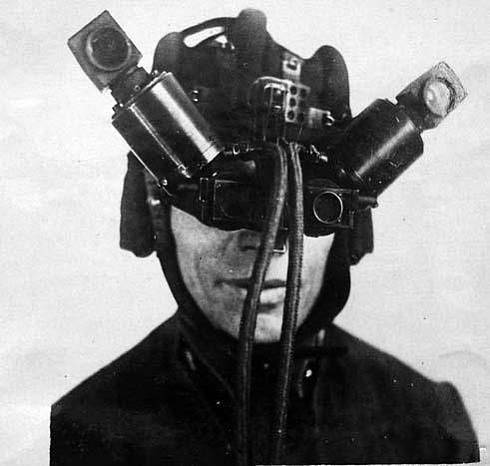
There are many designs of night vision devices. One of them is night vision binoculars for humans. The first such binoculars consisted of two infrared periscopic telescopes mounted on a helmet-helmet. The power supply of the telescope was also mounted on a helmet and served as a counterweight at the same time.
For cars, tanks and airplanes, night-vision binoculars of a different design were developed, differing mainly by the method of fastening.
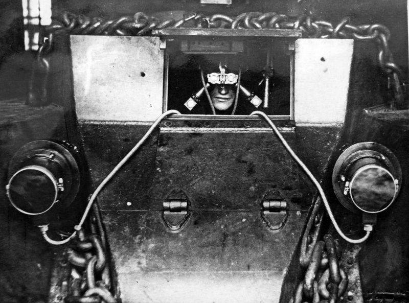
In the Soviet Union there was a secret laboratory under the leadership of V.I. Arkhangelskiy, which, having begun work on the creation of the first night-vision device around 1935, achieved significant success and tested X-NUMX-1939 for the first infrared devices known as "Ship" and "Pipe". They were intended for BT-1940 tanks. Preserved unique photos of the first developments.
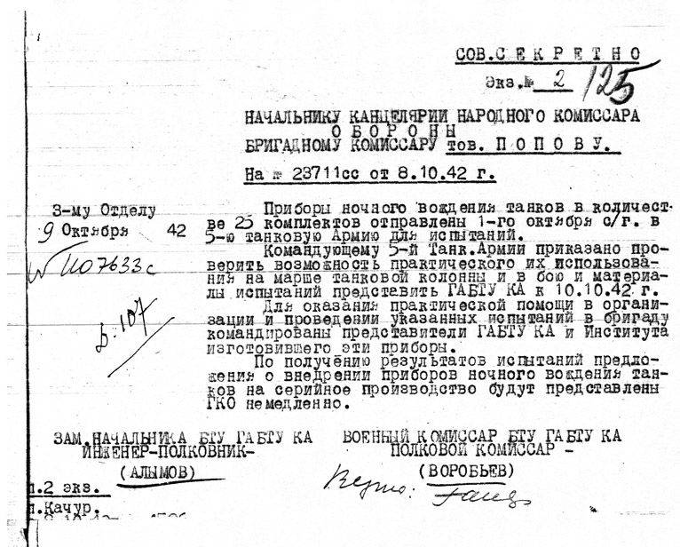
In 1942, the military commissar of the armored directorate of the Main Automobile and Armored Directorate of the Red Army (GABTU KA) regimental commissar Vorobyov sent the 9 of October 1942 a report of the following nature: “To the head of the office of the People’s Commissar of Defense, brigade commissar Comrade Popov. Devices of night driving of tanks in the number of 25 sets were sent on October 1 of this year to the fifth tank army for testing. The commander of the 5 Tank Army was ordered to check the possibility of their practical use on the march of the tank column and present the GABTU KA to 10.10 in combat and test materials. 1942 of the year. To provide practical assistance in organizing and conducting these tests, representatives of the State Bureau of Technical Standards of the Spacecraft and the Institute, who made these devices, were sent to the brigade.
Upon receipt of the test results, proposals for the introduction of night-driving tanks for mass production will be submitted immediately. ” It was about tanks T-34.
At the end of the Second World War, infrared telescopes were used to observe and conduct aimed fire in the dark. They were produced portable or installed in fixed installations.
Light portable constructions of infrared telescopes combined the telescope itself and the illuminator as one device. Illuminators in such devices were ordinary lights, closed by a filter. For aiming fire, infrared telescopes (they were also called sniper and super schniper) strengthened on sniper and automatic rifles, machine guns and other types of small arms. The first mention of the use of a new type of weapon relates to the American operation conducted in Okinawa in 1945 year.
For example, a light machine gun was launched, equipped with an infrared telescope with a medium-sized electron-optical converter. And the illuminator for such a sight served as a searchlight, which was installed at some distance from the machine gun.
With the advent of infrared technology, scientists began to look for ways to counter. In 1946, special detection devices appear. One of them was created in France and received the name metascop.
In the first meta scan, an infrared image with a lens was projected onto a screen with a phosphor (from Lat. Lumen - light and ancient Greek φορ) - carrier) - a substance capable of converting the energy it absorbs into light (luminescence). An image appeared on the screen that could be viewed through the eyepiece. The luminescence of the phosphor from direct exposure to infrared rays occurred if the phosphor was previously excited. The excitation was performed by ultraviolet light, after which it lasted for several days.
The French metascop was small in size and weighed about 200 grams. He allowed at a distance of several kilometers to detect infrared illuminators.
Another one of the original detection devices IRI-03 worked differently. When infrared rays hit it, a sound signal was created as a result of the beating of the two frequencies f1 and f2. The frequency f2 is variable and depends on the degree of irradiation of the receiving element of the device such as a photocell, the frequency f1 is constant.
The pitch of the beat frequency was used to make a conclusion about the intensity of infrared rays, i.e. estimated range to source.
Thermal intelligence devices
Thermal reconnaissance devices began to be used during the Second World War to search for and determine the bearing (angle of sight) of surface ships, submarines, airplanes, and after the war - missiles and other objects, as well as for spatial orientation of spacecraft and satellites. In particular, during the Second World War, heat-finders were used - devices for determining the target bearing by its own thermal radiation without additional lighting.
In the Soviet Union, with 1927, active development was carried out on the introduction of heat finders in the Air Force and Navy. And we must admit that in this direction the Navy has advanced more than other types of troops. And that's why.
In 1929, the Military Technical Directorate of the Red Army commissioned the All-Union Electrotechnical Institute to test the possibility of detecting a moving aircraft from its thermal (infrared) radiation. It turned out that the main obstacle is the weather, or rather the dense clouds and the moon, which were taken by the equipment for the plane. It was decided to curtail work in this area and test the new method in other branches of the military.
The "heat finder" caught in the Navy.
Already in the 30-ies on the torpedo boats based in Peypiy Bay, the first heat finders were installed. The range at which the finder could locate a merchant ship was 8-9 kilometers, the patrol ship 12-16 kilometers, the squadron destroyer 16-22 kilometer, the submarine could catch the submarine at a distance of 3-XNXXXXXXXXXXXXXXXXXXXXXXXXXXXXXXXXXXHXXXXXXXXX of in a submarine in a surface position, the device could catch at a distance of 4-XNXXXXXXXXXXXXXXXXXXXXXXXXXX of 4-5 kilometers.
According to the product line attached to the plan of orders of the People’s Commissariat of Defense, People’s Commissariat of the Naval fleet and the People's Commissariat of Internal Affairs, during 1940 it was planned to manufacture eight coastal (mobile) heat direction finders. The total cost of the work was 2 million 800 thousand rubles. In the first quarter, the main contractor - the People’s Commissariat of the Shipbuilding Industry (NKSP) - was supposed to deliver two such heat direction finders. Installation work was supposed to be performed directly on the spot, in the fleet. Heat direction finders were manufactured at military plant No. 192.
At the beginning of World War II on the Black Sea Fleet 15 improved such installations were involved, and by November the fleet received 18 heat finders, which greatly facilitate the protection of the main naval base - Sevastopol.
In total, during the war years, about seven thousand different devices supplied by leading research institutes were supplied to the army and the fleet.
The All-Union State Institute of Telemechanics and Communications (VGITIS), renamed 1936 to Scientific Research Institute-10, and now the Marine Research Institute of Radio Electronics Altair, was also involved in the development of infrared technology. A new direction for the creation of infrared technology was decided to be developed in 1939 year, a special laboratory of heat-finding was created under the direction of N. D. Smirnov. In the laboratory, they were mainly engaged in two areas - the development of heat finders for cars and ships. Employees worked in record time. Already in the year of the formation of the laboratory in Sevastopol, they conducted the first tests of the automotive heat finder. After minor changes and necessary modifications, the same direction finder was tested for strength when detecting maritime transport. The result is 30 kilometers. This heat finder began to be mass-produced; they were equipped with coastal naval units. Created also in 1939, the compact coastal stationary heat finder-heatblock (BTP-39) and ship heat finder, which received the cruiser "Red Caucasus" became reliable means of struggle against the German ships.
The entire naval staff of the Black Sea Fleet learns how to handle the Omega-VEI direction finders, the Gamma-K binoculars and the Olyga joint navigation equipment.
Thanks to the passive principle of operation, the heat finder, like other tracking and search devices of thermal reconnaissance, had a number of advantages over radars.
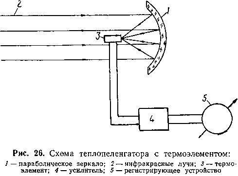
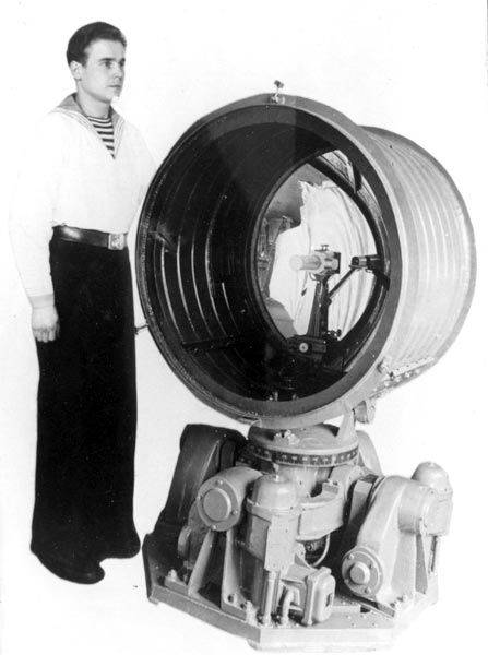
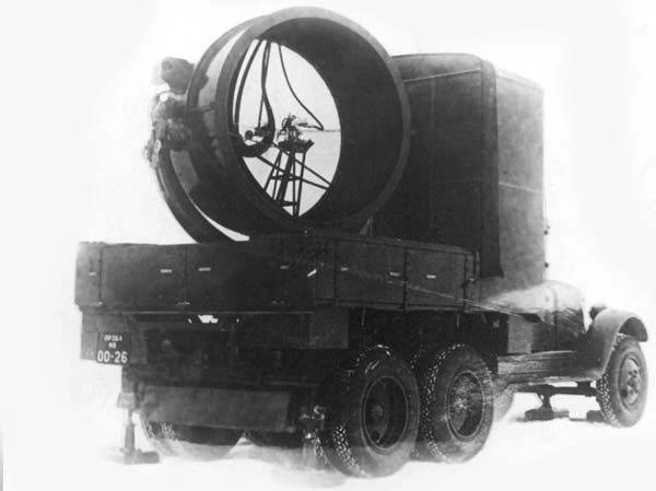
The heat finder consisted of the following main parts:
- a receiver with a parabolic mirror with a diameter of 60-150 centimeters, the focus of which was the receiver of infrared rays (thermoelement, bolometer, photoresistance);
- modulator in the form of a rotating disk with holes for interrupting (modulating) infrared rays on the way from the target to the receiver;
- an amplifier — an electronic device for amplifying a signal from a receiver to a value sufficient to trigger tracking automatics;
- indicators showing the target and its bearing on the screen.
Depending on the purpose and tasks performed, the heat finder differed in design and layout.
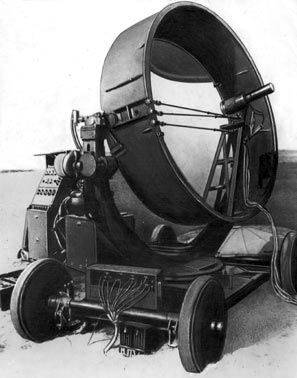 If the heat finder was used to search for marine ships, whose angular displacements in the field of view of the heat finder are relatively slow, the infrared ray receivers in it served as a thermoelement or a bolometer. The mechanical design of such a heat finder did not require additional devices to move the line of sight in elevation, as it was necessary to observe only in azimuth.
In the anti-aircraft heat finder for tracking aircraft, thermoelements and bolometers were unsuitable due to the large inertia. It began to use photoresistance. The design of such a heat finder had a device for installing the object in elevation and azimuth. Of the heat finders used during the Second World War, the German heat finder Donau-60 with an antimony bolometer is known. The range of its action on large ships was 30-35 kilometers.
The anti-aircraft finder with a sulfur-lead photoresistance had a direction finding accuracy of 1 / 10 degrees, and the range of action on a heavy bomber with a piston engine reached 20 kilometers in clear weather.
After the war, with the growth of speed of jet aircraft and long-range guided missiles, the aerodynamic heating of the hull plating increased dramatically, which in turn increased the intensity of infrared radiation and the efficiency of infrared technology.
The long range, high accuracy of determining the angular coordinates made it possible to use thermal reconnaissance devices for the long-range detection of airplanes, artificial Earth satellites, ballistic missiles in the final part of the trajectory, for measuring the angular coordinates of the rockets in the initial part of the trajectory (in the engine operation area), reconnaissance of space and other purposes.
For tracking the head body of a ballistic missile in the final segment of the trajectory, special radiometers operating in the infrared region of the spectrum have become increasingly used. Especially favorable conditions for this were created at the entrance of the head body of the rocket into the dense layers of the atmosphere. The head body, entering the atmosphere, created the front of the shock wave. A high-temperature layer is formed behind this front. In this layer, the air is intensely ionized and radiates. The high-temperature luminous area of air in front of the head housing is an excellent “hint” for both visual detection and tracking with infrared devices.
One after another, devices are created to track the flight of rockets. In principle, each of them was a portable infrared radiation receiver, which could also be installed on a radar antenna in order to use the tracking system of the latter.
For example, in the USA, spectral and radiometric tests of infrared radiation of the head body of the Jupiter intercontinental ballistic missile were conducted. At the same time, an infrared portable radiometer began to be used as the main tracking device. In the radiometer of this type, the receiver is the photoresistance of lead sulfide or a germanium bolometer. A rotating disk with notches was installed in front of the receiver, which by 100 percent modulated the radiation flux from the rocket's main body, and the background (sky) radiation was practically not modulated. At the output, a variable signal was obtained from the radiation flux of the rocket head hull. Since discs with cutouts of various widths were used, the work of such a radiometer took place at different times of the day. The weight of this type of radiometer was 6-10 kilograms.
Equally important in combat is tracking a ballistic missile in the initial part of the trajectory of movement. The data obtained were then used to calculate the flight path of the rocket's main body.
For example, in the US Air Force test rocket center, the first tracking experiments were carried out on Atlas and Jupiter missiles at a distance of more than 16 kilometers. The infrared device was mounted on the frame of the antenna device of the radar station, and the electronic node was installed on the basis of the antenna. The tracking system could be automatically controlled by either radar or infrared devices. A television camera was mounted near the receiver, with which the operator, who was in the back of the locator, could introduce the rocket into the field of view of the device before its launch. With the advent of the exhaust flame, the tracking device captured it and automatically monitored the flame during the entire time the engine was running. At distances exceeding 16 kilometers, a radar tracking system was introduced.
Simultaneously with these works, scientists conducted active development of infrared instruments for obtaining intelligence information from space. Exploration from space has a number of important advantages. One of them is the ability to view the Earth as a whole in a short period of time and obtain information about the temperature distribution on Earth, the change in thermal radiation and other important parameters related to temperature. But the main purpose of space intelligence is to collect information about the alleged enemy.
In 1960, the United States Meteorological Satellites of the Tyros series introduced infrared ray sensors in the form of two types of radiometers. With the help of three-stage Tor rockets in November 1960, the Tyros-2 was launched, and the Tyros-3 was launched in July, 1961. The infrared receiver and optical system were rigidly fixed with respect to the axis of rotation of the satellite. Thanks to the rotation of the satellite, the Earth’s surface was viewed. The signal from the receiver output was amplified and recorded on a tape recorder. When the satellite passed over the reading station, the information was transmitted to the Earth via the telemetric channel. The principle of operation of such a device was similar to the principle of the outdated by that time television scanning system with a Paul Nipkov disc.
The US Samos-2 reconnaissance satellite, which was launched in January 1960 using the Atlas two-stage rocket, was also equipped with infrared-powered equipment.
In the next year, 1961, the United States, equipped its Midas reconnaissance satellites with infrared-powered equipment designed to detect launches of intercontinental ballistic missiles. Thus, using the Midas-4 satellite in October 1961, the Titan rocket was detected 90 seconds after its launch at an altitude of 60 kilometers above the Earth. Data on this detection was transmitted to ground stations.
Infrared homing systems
With the advent of new devices, the creation of homing systems became possible. Several design bureaus in the Soviet Union at once from about the middle of the 30-s began the task of creating self-guided projectiles. The first was the self-guided planning torpedo, which was worked out by the research institute 1 (headed by A.A. Rozanov) and other design bureaus.
According to the construction of the scheme and the principle of operation, infrared homing systems are a closed loop of automatic control (such systems were later called tracking).
Tracking the target and controlling the rocket were made by the following main components included in the control system: a tracking homing head, closed with a fairing transparent to infrared rays, with an optical system and a receiver of infrared rays of the type of photoresistance. Tracking homing heads were subsequently mounted on gyroscopic and gyrostabilized systems.
It also included an electronic system, including an amplifier and a command selection unit, for converting and amplifying signals from the receiver to a value sufficient to trigger automation and electric motors. Electric drives and automatics were designed to hold the optical axis of the homing head in the direction of the target, as well as to deflect the rocket rudders at the pitch and yaw angles.
The tracking system of the homing head ensured continuous retention of its optical axis in the direction towards the target by infrared radiation, regardless of the change in position of the geometric axis of the rocket in space.
If the target is out of sight of the head, a signal appears at the output of the electronic system, which by means of an electric actuator causes the head to turn on the target.
In this case, signals were sent to the rocket control system proportional to the angle between the optical axis of the head and the geometric axis of the rocket. An electrical error signal, acting on the electric actuators of the rudders, turns the rocket on the target.
In the post-war years, work on the creation of infrared homing systems to control air-to-air, air-to-ground, and ground-to-ground missiles was conducted in the USA, England, France, Italy and Switzerland. The Americans could boast of an infrared homing system installed in the Sidewinder and Falcon air-to-air missiles, which armed the fighters of the Navy and the US Air Force to defeat aerial targets with supersonic speeds. For example, the Sidewinder projectile fired from the F9F-8 fighter hit a tracer (luminous source) mounted on the end of the wing of a flying remote-controlled target F6F without damaging the target itself.
... This topic is amazing and immense. Over the past decades, infrared technology has become familiar and mundane. On the basis of new developments, new types of weapons are being created, the use of which is on the conscience of every belligerent. Now on sale you can buy infrared sights and all the necessary equipment in stores, the price of which goes up to the price for 10000 rubles for one unit. The fact that in the 30-ies was a state-important object and strictly classified, today has become the common property.
Information