Axial motors E. Michella (Australia)
Since the advent of gasoline internal combustion engines, there have been constant attempts to reduce the size of such products. So, in the last years of the XIX century, Karl Bentz proposed the so-called. an opposed engine in which the cylinders were located in the same plane, on different sides of the crankshaft. A little later, at the beginning of the 20th century, the idea of an axial engine with the location of cylinders along the main shaft was proposed. Sooner or later someone had to try to “cross” these two ideas. The author of this proposal in the end was the Australian engineer Anthony Michell.
Since the end of the nineteenth century, Anthony George Maldon Michell (Anthony George Maldon Michell) has been engaged in various projects in the field of mechanics. For example, he is the author of a widespread bearing design in which the lubricant is distributed among the parts due to their movement. In 1920, Michelle attempted to create his own engine of the original non-standard design. It should be noted that the Australian inventor is sometimes confused with his German counterpart Hermann Michel (Hermann Michel), also engaged in the subject of internal combustion engines, due to the similarity of spelling surnames.
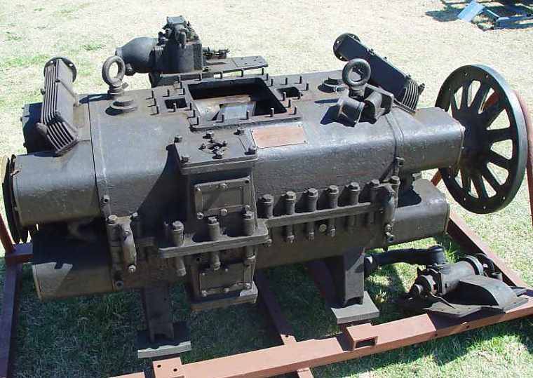
Engine assembly. Above you can see the ventilation window and faceplate. Photo by Douglas-self.com
Reflecting on the possibility of reducing the size of the engine, E. Michell came to the conclusion that it is necessary to abandon the crankshaft and associated units. In existing engines, such mechanisms took up at least half of the entire volume, which accordingly affected the dimensions. The refusal of the crankshaft, in turn, made it possible to significantly reduce and lighten the engine. However, the engine had to have a mechanism that transforms the reciprocating movement of the pistons into rotation of the main shaft.
Michell was probably familiar with the latest foreign developments, which allowed him to find the optimal solution to the problem. The new engine was proposed to build on the axial scheme. In this case, the cylinders had to be placed parallel to the shaft, and to convert their movement into rotation of the latter, it was proposed to use the washer mechanism traditional for such power plants.
The axial layout has a specific feature: with an increase in the number of cylinders mounted on a circle with the center in the form of a shaft, the diameter of the entire engine grows. Thus, the increase in power is directly related to the size of the engine. E. Michell proposed to bring the engine power to the desired value without increasing its diameter. For this, in his opinion, it was necessary to use the opposed placement of cylinders. This arrangement has already been used in the engine and showed good performance.
The development of the project of the new engine was carried out by the staff of the company Crankless Engine Company ("The company of crankless engines"). Among the employees of the company were T.L. Sherman, who continued to work on engines in the future, as well as Philip Edward Irving, who later became famous as a designer of racing equipment. For several months, the team conducted all the necessary research and design work, resulting in the emergence of the first Crankless Engine.
Drawing engine section. Figure Douglas-self.com
The overall layout of the engine, proposed by E. Michell, looked as follows. Inside a rectangular crankcase, there were several pairs of opposed cylinders. In the central part there was a place for the washer mechanism. Pass the main shaft along the longitudinal axis of the engine. This layout allows you to build engines with different number of cylinders. For example, in 1927, patents were obtained for engines with eight and ten cylinders, assembled in two blocks on either side of the central mechanism.
Of particular interest is the design of cylinders, pistons and washer mechanism proposed by Australian designers. In the boxer engine of the opposite design, pistons of cylinders, located on the same line, have no direct connection. Synchronization of each pair of cylinders is provided by connecting rods and crankshaft. The latter, in turn, is connected to other units.
Michella engine did not have a crankshaft, instead of which washer mechanism was used. To simplify the design, the cylinders were located at a short distance from each other and were connected by crankcase elements. In addition, each pair of cylinders received one dual piston. In fact, it consisted of two pistons of the “classical” design, interconnected by an additional central section. In the middle part connecting the extreme parts, a mechanism was provided for contact with the faceplate.
A pair of cylinders and a washer mechanism in section. Figure Douglas-self.com
The washer was a relatively thick metal disk of the desired diameter, mounted on the shaft at an angle to its axis. The installation angle of this part influenced the stroke of the piston, the volume of the combustion chamber and other engine parameters. The contact between the pistons and the faceplate was provided with a design based on the principles of operation of the Michell bearing. In the side surface of the dual piston there was a large slot, which provided for mounting for the installation of two liners. Each such liner was a flat metal plate with a hemispherical thickening. The hemisphere part was included in the mounting piston, and a flat surface had to slide on the faceplate. Due to the hinge mounting, a constant contact of the piston with the faceplate was ensured. The engine had a system of constant lubricant supply to the piston liners in order to avoid overheating or destruction of parts.
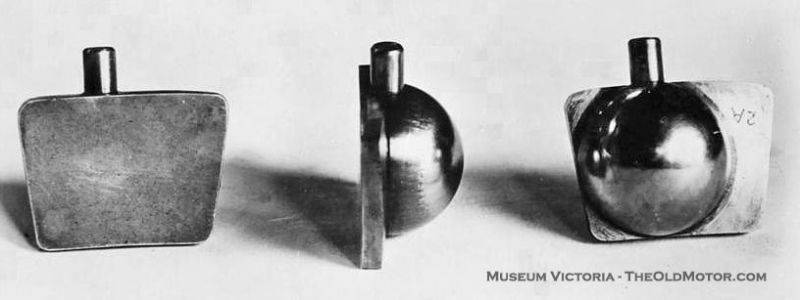
Twin piston inserts
Michella engines were proposed to equip the valve timing and exhaust systems. The valve holes were located in the cylinder head. Mechanisms of control valves through various gears associated with the main shaft. Provided exhaust manifolds, exhaust gases into a common pipe. The engine could be equipped with a liquid cooling system. In addition, a fan drive located in the crankcase bottom hole was connected to the main shaft. He had to blow air through the mechanisms of the engine and thereby further cool the parts exposed to the greatest thermal load. Bearings designed by E. Michella, despite their effectiveness, still did not exclude the production of heat. In the side of the engine should be placed drive and mechanisms of the oil pump. His task was to continuously supply liners and faceplate with lubricant.

Main shaft, faceplate and twin piston
One of the engines mentioned, which was the subject of the 1927 patent of the year, had eight cylinders with an internal diameter of 84 mm. The piston stroke was 90 mm. The distance between the axis of the main shaft and the longitudinal axis of the pistons was 214 mm, the radius of the faceplate was slightly larger. The washer was set at an angle 22,5 ° to the shaft axis. The total length of the block of opposed cylinders did not exceed 435 mm. The total engine length was 730 mm.
The development of the basic concept took several years. The formation of a general layout and characteristic features of the design allowed to begin the development of full-fledged engine projects suitable for mass production. Already in 1923, the company Crankless Engine Company introduced several engines with different numbers of cylinders and different characteristics. Engines with eight and ten cylinders could develop power, according to various sources, to HP 70-100.

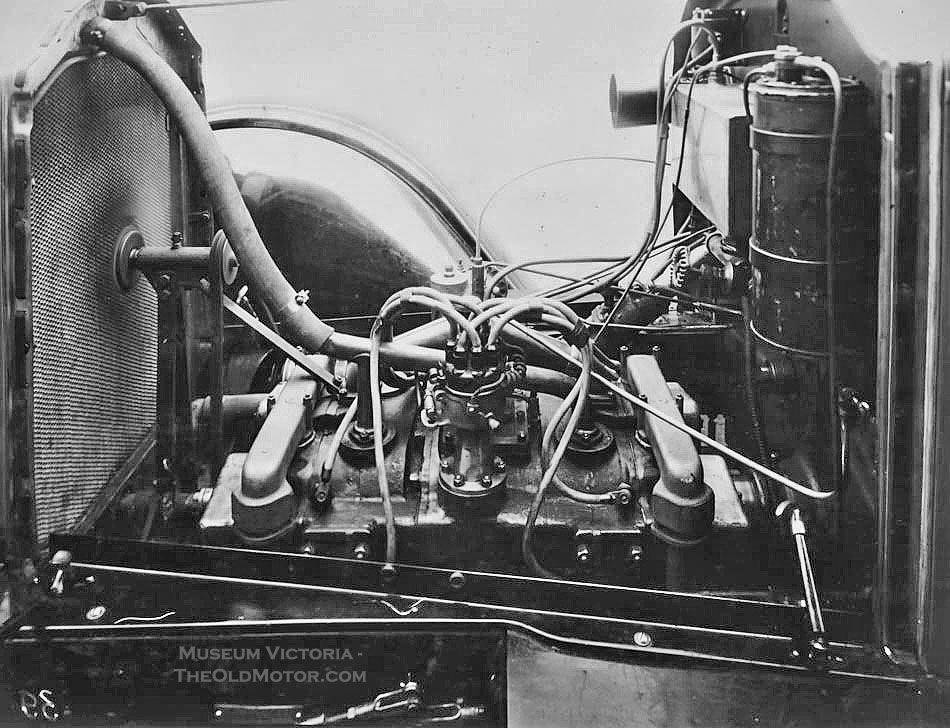
Engine in the engine compartment of the car
Known to test the engine Michella on the car. A car of Buick company was taken as a platform for such verification. The eight-cylinder engine of sufficient power was placed in the engine compartment of the car, and because of its small height there was a mass of free space under the hood. Thus, the proposed engines significantly exceeded the existing in terms of size and power.
There is evidence of the existence of a simplified engine project. Such a motor had only one side block with cylinders and the corresponding design of pistons, crankcase, etc. This design provided an additional reduction in size while maintaining power at the required level.
Shortly after the completion of the tests and the official "premiere" of the E. Michel engines, potential customers became interested. A fairly wide range of products allowed us to obtain contracts for the supply of fifty engines of various types with different capacities. At a minimum, 45 motors were built and shipped to customers. According to reports, among these serial engines were power plants for self-propelled vehicles, watercraft and industrial equipment.
Drawing of a simplified engine with one cylinder block. Figure Douglas-self.com[/ Center]
In total, the 50 engines supplied by the customer included the Crankless Engine Company into the list of the most successful axial motor manufacturers. Such equipment has never been in great demand, because of which even a few dozen of the produced engines made the manufacturer a record holder. Current successes have been a cause for optimism. In practice, the good mood of engine builders resulted in the creation of new projects. In 1927, eight types of engines were offered to customers based on common ideas and solutions.
However, the development of new engines did not lead to an increase in demand for them. The company's products sold worse and worse. In 1928, the last order received was completed. New Australian customers did not appear, which is why E. Michell was forced to stop building engines of his own design. Sold engines were used in various fields to develop a resource.
By this time, some foreign companies were interested in the idea of Michella. A number of organizations from the United States and the United Kingdom have bought a license to manufacture axial "Axial-free engines". As far as we know, American production lasted only a few years, after which it closed. The reasons were the same as in the case of the Crankless Engine Company: the internal combustion engines that emerged by this time were of greater interest to operators and, as a result, to manufacturers.
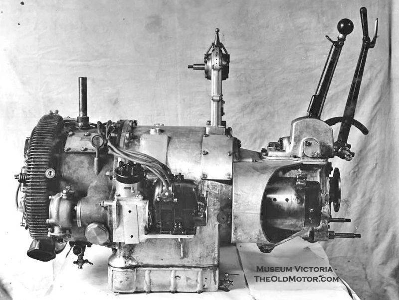
Automotive version of the engine Michella with transmission units
Nevertheless, Michell's development has found its niche. One of the license buyers was George Waller & Sons, a British company based in Stroud. This firm did not offer its products to the automotive industry and focused on manufacturing equipment for the industry. On the basis of the Australian design, new special-purpose modifications were created. For example, pumps for pumping natural gas with modernized Michell engines were quite popular among customers. The most powerful of these motors ran on gas taken from the pipeline and could pump up to 500 thousand cubic meters. feet per hour (more than 14 cubic meters).
Due to the limited market for such products, the British company could not boast of particularly large sales volumes. Nevertheless, the production of gas pumps and other equipment with Michell engines, which had a certain demand, continued until the 1971 year. During this time, 116 engines were built.
In total, more than 150-160 engines designed by Anthony Michell were used, which were used in automotive and other equipment. Operation of the latest British-made engines continued until the eighties. It must be admitted that in terms of production and success among customers, Michella engines lose to a large number of other engines, created in the late twenties. However, they turned out to be one of the most successful members of the axial motor family during their entire existence. This is confirmed by the number of engines produced and the duration of their operation.
On the materials of the sites:
http://theoldmotor.com/
http://douglas-self.com/
http://museumvictoria.com.au/
http://adb.anu.edu.au/
Since the end of the nineteenth century, Anthony George Maldon Michell (Anthony George Maldon Michell) has been engaged in various projects in the field of mechanics. For example, he is the author of a widespread bearing design in which the lubricant is distributed among the parts due to their movement. In 1920, Michelle attempted to create his own engine of the original non-standard design. It should be noted that the Australian inventor is sometimes confused with his German counterpart Hermann Michel (Hermann Michel), also engaged in the subject of internal combustion engines, due to the similarity of spelling surnames.
Engine assembly. Above you can see the ventilation window and faceplate. Photo by Douglas-self.com
Reflecting on the possibility of reducing the size of the engine, E. Michell came to the conclusion that it is necessary to abandon the crankshaft and associated units. In existing engines, such mechanisms took up at least half of the entire volume, which accordingly affected the dimensions. The refusal of the crankshaft, in turn, made it possible to significantly reduce and lighten the engine. However, the engine had to have a mechanism that transforms the reciprocating movement of the pistons into rotation of the main shaft.
Michell was probably familiar with the latest foreign developments, which allowed him to find the optimal solution to the problem. The new engine was proposed to build on the axial scheme. In this case, the cylinders had to be placed parallel to the shaft, and to convert their movement into rotation of the latter, it was proposed to use the washer mechanism traditional for such power plants.
The axial layout has a specific feature: with an increase in the number of cylinders mounted on a circle with the center in the form of a shaft, the diameter of the entire engine grows. Thus, the increase in power is directly related to the size of the engine. E. Michell proposed to bring the engine power to the desired value without increasing its diameter. For this, in his opinion, it was necessary to use the opposed placement of cylinders. This arrangement has already been used in the engine and showed good performance.
The development of the project of the new engine was carried out by the staff of the company Crankless Engine Company ("The company of crankless engines"). Among the employees of the company were T.L. Sherman, who continued to work on engines in the future, as well as Philip Edward Irving, who later became famous as a designer of racing equipment. For several months, the team conducted all the necessary research and design work, resulting in the emergence of the first Crankless Engine.
Drawing engine section. Figure Douglas-self.com
The overall layout of the engine, proposed by E. Michell, looked as follows. Inside a rectangular crankcase, there were several pairs of opposed cylinders. In the central part there was a place for the washer mechanism. Pass the main shaft along the longitudinal axis of the engine. This layout allows you to build engines with different number of cylinders. For example, in 1927, patents were obtained for engines with eight and ten cylinders, assembled in two blocks on either side of the central mechanism.
Of particular interest is the design of cylinders, pistons and washer mechanism proposed by Australian designers. In the boxer engine of the opposite design, pistons of cylinders, located on the same line, have no direct connection. Synchronization of each pair of cylinders is provided by connecting rods and crankshaft. The latter, in turn, is connected to other units.
Michella engine did not have a crankshaft, instead of which washer mechanism was used. To simplify the design, the cylinders were located at a short distance from each other and were connected by crankcase elements. In addition, each pair of cylinders received one dual piston. In fact, it consisted of two pistons of the “classical” design, interconnected by an additional central section. In the middle part connecting the extreme parts, a mechanism was provided for contact with the faceplate.
A pair of cylinders and a washer mechanism in section. Figure Douglas-self.com
The washer was a relatively thick metal disk of the desired diameter, mounted on the shaft at an angle to its axis. The installation angle of this part influenced the stroke of the piston, the volume of the combustion chamber and other engine parameters. The contact between the pistons and the faceplate was provided with a design based on the principles of operation of the Michell bearing. In the side surface of the dual piston there was a large slot, which provided for mounting for the installation of two liners. Each such liner was a flat metal plate with a hemispherical thickening. The hemisphere part was included in the mounting piston, and a flat surface had to slide on the faceplate. Due to the hinge mounting, a constant contact of the piston with the faceplate was ensured. The engine had a system of constant lubricant supply to the piston liners in order to avoid overheating or destruction of parts.

Twin piston inserts
Michella engines were proposed to equip the valve timing and exhaust systems. The valve holes were located in the cylinder head. Mechanisms of control valves through various gears associated with the main shaft. Provided exhaust manifolds, exhaust gases into a common pipe. The engine could be equipped with a liquid cooling system. In addition, a fan drive located in the crankcase bottom hole was connected to the main shaft. He had to blow air through the mechanisms of the engine and thereby further cool the parts exposed to the greatest thermal load. Bearings designed by E. Michella, despite their effectiveness, still did not exclude the production of heat. In the side of the engine should be placed drive and mechanisms of the oil pump. His task was to continuously supply liners and faceplate with lubricant.
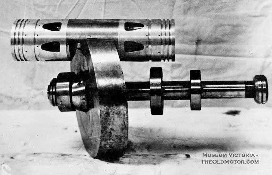
Main shaft, faceplate and twin piston
One of the engines mentioned, which was the subject of the 1927 patent of the year, had eight cylinders with an internal diameter of 84 mm. The piston stroke was 90 mm. The distance between the axis of the main shaft and the longitudinal axis of the pistons was 214 mm, the radius of the faceplate was slightly larger. The washer was set at an angle 22,5 ° to the shaft axis. The total length of the block of opposed cylinders did not exceed 435 mm. The total engine length was 730 mm.
The development of the basic concept took several years. The formation of a general layout and characteristic features of the design allowed to begin the development of full-fledged engine projects suitable for mass production. Already in 1923, the company Crankless Engine Company introduced several engines with different numbers of cylinders and different characteristics. Engines with eight and ten cylinders could develop power, according to various sources, to HP 70-100.
Engine in the engine compartment of the car
Known to test the engine Michella on the car. A car of Buick company was taken as a platform for such verification. The eight-cylinder engine of sufficient power was placed in the engine compartment of the car, and because of its small height there was a mass of free space under the hood. Thus, the proposed engines significantly exceeded the existing in terms of size and power.
There is evidence of the existence of a simplified engine project. Such a motor had only one side block with cylinders and the corresponding design of pistons, crankcase, etc. This design provided an additional reduction in size while maintaining power at the required level.
Shortly after the completion of the tests and the official "premiere" of the E. Michel engines, potential customers became interested. A fairly wide range of products allowed us to obtain contracts for the supply of fifty engines of various types with different capacities. At a minimum, 45 motors were built and shipped to customers. According to reports, among these serial engines were power plants for self-propelled vehicles, watercraft and industrial equipment.
Drawing of a simplified engine with one cylinder block. Figure Douglas-self.com
In total, the 50 engines supplied by the customer included the Crankless Engine Company into the list of the most successful axial motor manufacturers. Such equipment has never been in great demand, because of which even a few dozen of the produced engines made the manufacturer a record holder. Current successes have been a cause for optimism. In practice, the good mood of engine builders resulted in the creation of new projects. In 1927, eight types of engines were offered to customers based on common ideas and solutions.
However, the development of new engines did not lead to an increase in demand for them. The company's products sold worse and worse. In 1928, the last order received was completed. New Australian customers did not appear, which is why E. Michell was forced to stop building engines of his own design. Sold engines were used in various fields to develop a resource.
By this time, some foreign companies were interested in the idea of Michella. A number of organizations from the United States and the United Kingdom have bought a license to manufacture axial "Axial-free engines". As far as we know, American production lasted only a few years, after which it closed. The reasons were the same as in the case of the Crankless Engine Company: the internal combustion engines that emerged by this time were of greater interest to operators and, as a result, to manufacturers.

Automotive version of the engine Michella with transmission units
Nevertheless, Michell's development has found its niche. One of the license buyers was George Waller & Sons, a British company based in Stroud. This firm did not offer its products to the automotive industry and focused on manufacturing equipment for the industry. On the basis of the Australian design, new special-purpose modifications were created. For example, pumps for pumping natural gas with modernized Michell engines were quite popular among customers. The most powerful of these motors ran on gas taken from the pipeline and could pump up to 500 thousand cubic meters. feet per hour (more than 14 cubic meters).
Due to the limited market for such products, the British company could not boast of particularly large sales volumes. Nevertheless, the production of gas pumps and other equipment with Michell engines, which had a certain demand, continued until the 1971 year. During this time, 116 engines were built.
In total, more than 150-160 engines designed by Anthony Michell were used, which were used in automotive and other equipment. Operation of the latest British-made engines continued until the eighties. It must be admitted that in terms of production and success among customers, Michella engines lose to a large number of other engines, created in the late twenties. However, they turned out to be one of the most successful members of the axial motor family during their entire existence. This is confirmed by the number of engines produced and the duration of their operation.
On the materials of the sites:
http://theoldmotor.com/
http://douglas-self.com/
http://museumvictoria.com.au/
http://adb.anu.edu.au/
Information