Rotational engine. Dirty warrior ...
Today we’ll talk about the engine, the heyday of which fell on the period of time when aviation I haven’t left the state of “flying shelves”, but when these same shelves already felt quite confident in the air.
The basic principles of aircraft and engine-building quickly took a steady shape. There were more and more models of engines for airplanes, and with them both new victories and new problems in the engine industry. Designers and engineers sought (as it is, in general, is happening now :-)) to maximally facilitate the engines and at the same time maintain or even increase their traction efficiency.
On this wave, a rotated engine appeared for the then airplanes. Why for airplanes? Because by itself this type of engine was developed even much earlier than the first flight of the Wright brothers.
But first things first. What is a rotary engine ... In English, the rotary engine (which, by the way, in my opinion is strange, because the same word denotes a rotary engine (Wankel engine)). This is an internal combustion engine in which cylinders with pistons (their odd number) are located radially in the form of a star, usually four-stroke.
Working fuel - gasoline, ignition comes from the spark plugs.
In appearance, it is very similar to the well-known radial (star-shaped) piston engine that appeared almost simultaneously with it and well today. But this is only in a non-working state. When you start a rotary engine on a person who is ignorant of him makes a strong impression.
This happens because his work looks very unusual at first glance. Indeed, together with the screw rotates and the entire cylinder block, that is, in fact, the whole engine. And the shaft on which this rotation takes place is fixed. However, in mechanical terms, there is nothing unusual here. Just a matter of habit :-).
The fuel-air mixture due to the rotation of the cylinders cannot be supplied to them in the usual manner; therefore, it gets there from the crankcase, where it is fed through a hollow shaft from the carburetor (or its replacement device).
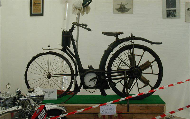
For the first time in stories A patent for the rotary engine was obtained by the French inventor Félix Millet in 1888. Then they put this engine on a motorcycle and showed it at the Paris World Exhibition in 1889.
Later, Félix Millet engines were installed on cars, one of which took part in the world's first Paris – Bordeaux – Paris car race in 1895, and since 1900, these engines were put on cars by the French company Darracq.
In the future, engineers and inventors began to pay attention to the rotary engine from the point of view of its use in aviation.
The first in this regard was Stephen Balzer, a former New York watchmaker, who created his rotary engine in 1890 and became the author (with engineer Charles M. Manly) of the first ever engine developed specifically for an airplane known as the Manly-Balzer engine.
Almost simultaneously, he worked with the American engineer Adams Farwell, who built cars with rotary engines from 1901 of the year.
According to some information, the principles of the design of its engines were taken as a basis by the manufacturers of the subsequently famous Gnome engines.
What was it that attracted engineers in a rotary engine? What is so useful for aviation?
There are two main features that are its main positive qualities. The first is the smallest (at that time) weight compared with engines of the same power. The fact is that the rotational speeds of the then engines were low and to obtain the required power (on average, then, of the order of 100 hp (75 kW)), the ignition cycle of the air-fuel mixture made itself felt by very tangible jolts.
To avoid this, the engines were supplied with massive flywheels, which naturally entailed a heavier structure. But for a rotary engine, the flywheel was not needed, because the engine itself was spinning, having enough mass to stabilize the stroke.
Such engines differed smoothness and uniformity. The ignition was made sequentially in each cylinder through one in a circle.
The second feature was good cooling. The metallurgical industry in those days was not as developed as it is now and the quality of the alloys (in terms of heat resistance) was not too high. Therefore, good cooling was required.
Aircraft flight speeds were not high, so simple cooling with the oncoming flow of a stationary engine was insufficient. And the rotary engine here was in a more advantageous position, because it itself rotated with sufficient speed for effective cooling and the cylinders were blown well by air. At the same time, they could be both smooth and ribbed. Cooling was quite effective even when the engine was running on the ground.
Now let's digress for a couple of useful videos about the work of a rotary engine. The first is the modeling of his work on the computer. The second shows the work of the “insides” of the engine Le Rhône.
The flowering of rotary engines fell on the First World War. At that time, aviation was already seriously involved in hostilities and air battles were not uncommon. Airplanes and engines for them were made by all major participants in the war.
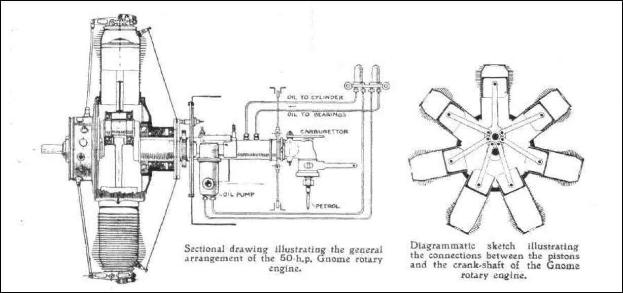
Of the engine-building systems, one of the most famous was the French firm Société des Moteurs Gnome, which was once engaged in the production of internal combustion engines for industrial production. In 1900, she bought a license to manufacture a small single-cylinder stationary engine (horsepower 4) Gnom from the German company Motorenfabrik Oberursel. This engine was sold in France under the French name Gnome and so successfully that the name was used in the name of the company.
Later on the basis of the Gnome was developed rotary engine Gnome Omega, which had a considerable number of modifications and was installed on a variety of aircraft. There are also other massively produced engines of this company. For example, the Gnome 7 Lambda - seven-cylinder, horsepower 80 hp and its continuation Gnome 14 Lambda-Lambda (160 hp), a two-row rotary engine with 14-th cylinders.
The Gnome Monosoupape engine (one valve) is widely known, it was launched in the 1913 year and was considered one of the best engines in the initial period of the war. This “best engine” :-) had only one valve used for both exhaust and air intake. For the flow of fuel into the cylinder from the crankcase, a number of special holes were made in the cylinder skirt. The engine was beskarbyutorny and because of the simplified control system was lighter and consumed, besides less oil.
He had practically no control. There was only a fuel valve that fed gas through a special nozzle (or sprayer) into the hollow fixed shaft and then into the crankcase. This crane could try to enrich or deplete the air-fuel mixture in a very narrow range, which was of little use.
They tried to use for the purpose of control the change in valve timing, but they quickly refused to do this, because the valves began to burn. As a result, the engine constantly worked at maximum speed (as, by the way, all rotary engines :-)) and was controlled only by turning off the ignition (more on that below :-)).
Another well-known French company producing rotary engines was Société des Moteurs Le Rhône, which began its work with 1910. One of its most famous engines was Le Rhône 9C (power 80 hp) and Le Rhône 9J (110 hp). Their characteristic feature was the presence of special pipelines from the crankcase to the cylinders for supplying the fuel-air mixture (a bit like the inlet manifolds of modern internal combustion engines).

Le Rhône and Gnome initially competed, but then merged and with 1915, they already worked together under the name Société des Moteurs Gnome et Rhône. The 9J engine was, in general, already their joint product.
Interestingly, the aforementioned German company Motorenfabrik Oberursel in 1913 purchased licenses for the production of the now French rotary Gnome engines (although it was the ancestor of this brand, you can say :-)) and a little later the Le Rhône engines. She released them under her own names: Gnome, like the U-series and Le Rhône, as the UR-series (from the German word Umlaufmotor, meaning a rotary engine).
For example, the Oberursel U.0 engine was similar to the French Gnome 7 Lambda and was installed initially on the Fokker EI aircraft, and the Oberursel U.III engine is a copy of the two-row Gnome 14 Lambda-Lambda.
In general, the company Motorenfabrik Oberursel throughout the war produced quite a large number of clone engines of French models, which were then put on airplanes that were opponents of the French and their allies in aerial combat. These are the tricks of life :-) ...
Among other well-known engine-building companies, the French company Société Clerget-Blin et Cie (the word Blin interesting for the Russian ear in the name means the name of one of the founders, industrialist Eugene Blin :-)) is also listed with its famous Clerget 9B engine.

Many engines were manufactured in the UK under licenses. The same factories produced the British engines developed by Walter Owen Bentley (the same Bentley) Bentley BR.1 (replacing the Clerget 9B on the Sopwith Camel) and Bentley BR.2 for the Sopwith 7F.1 Snipe fighter.
On the Bentley engines in the design of the pistons were first used aluminum alloys. Prior to this, all engines had cast-iron cylinders.
Now let us remember about other features of the rotary engine, which, so to speak, do not add benefits to it :-) (most often just the opposite).
A little about management. A modern (stationary, of course :-)) piston engine, whether it is inline or star-shaped, is relatively easy to control. The carburetor (or injector) forms the desired composition of the fuel-air mixture and with the help of the throttle the pilot can regulate its flow to the cylinders and, thus, change the engine speed. To do this, in essence, there is a handle (or pedal, as you wish :-)) gas.
With a rotary engine, things are not so simple :-). Despite the difference in design, most of the rotary engines had a controlled intake valve on the cylinders, through which the fuel-air mixture entered. But the rotation of the cylinders did not allow the use of a conventional carburetor, which would support the optimal air-fuel ratio behind the throttle valve. The composition of the mixture entering the cylinders had to be adjusted to achieve the optimum ratio and stable engine performance.
For this, there was usually an additional air valve (“bloctube”). The pilot set the throttle lever to the desired position (often opening the throttle completely) and then using the air supply adjustment lever, he achieved stable engine operation at maximum speed, producing the so-called fine adjustment. At such speeds, and usually passed the flight.
Due to the large inertia of the engine (the mass of the cylinders is nevertheless rather big :-)), such adjustment was often done using the “spear method”, that is, it was possible to determine the desired amount of adjustment only in practice, and this practice was necessary for confident control. Everything depended on the engine design and pilot experience.
The entire flight took place at the maximum engine speed, and if for any reason it was necessary to reduce it, for example, to land, the control actions should be in the opposite direction. That is, the pilot had to close the throttle and then regulate the air supply to the engine again.
But such a “control” was, as you understand, rather cumbersome and time consuming, which is not always in flight, especially during landing. Therefore, the ignition shutdown method was used more often. Most often this was done through a special device that allows you to turn off the ignition completely or in separate cylinders. That is, the cylinders without ignition stopped working and the engine as a whole was losing power, which was what the pilot needed.
This method of management was widely used in practice, but it dragged along a lot of problems. Fuel, together, by the way, with oil, despite the ignition off, continued to flow into the engine and, unburntly, safely left it and then accumulated under the hood. Since the engine is very hot, there is a danger of a serious fire. The then "light bookshelves" burned very easily and quickly :-).
Therefore, engine hoods had a cut-out at about one third of the perimeter, or at worst serious drainage taps, so that all this filth could be removed by the oncoming flow. Most often, of course, she smeared on the fuselage.
In addition, candles in non-operating cylinders could be flooded and oily and restarting was therefore not guaranteed.
By 1918, the French engine company Société Clerget-Blin et Cie (Clerget 9B rotary engines), based on the apparent danger of using a power reduction method by turning off the ignition, the following control method was recommended in the engine manual.
If it is necessary to reduce the engine's power, the pilot shuts off the fuel supply by closing the throttle (with the throttle). In this case, the ignition does not turn off, and the candles continue to “spark” (protecting themselves from oiling). The screw rotates as a result of the autorotation effect, and if it is necessary to start the fuel valve, it simply opens into the same position as before closing. The engine starts ...
However, according to pilots, who fly today on reconstructed or replicas of aircraft of that time, the most convenient mode of reducing power is still turning off the ignition, despite all the “dirt” that rotary engines eject :-).
Airplanes with such engines in general did not differ in high purity. I already said about the fuel in the disconnected cylinders, but there was also oil. The fact is that due to the rotating cylinder block, the possibility of pumping fuel from the crankcase was very problematic, so it was impossible to organize a full-fledged lubrication system.

But without lubrication, no mechanism will work, so it, of course, existed, but in oh-oh-very simplified form. Oil was supplied directly to the cylinders, to the fuel-air mixture. On most engines, there was a small pump for this, which fed oil through a hollow (fixed, as already known :-)) shaft through special channels.
As a lubricating oil, castor oil was used, the best in those times (natural vegetable oil) for these purposes. It also did not mix with fuel, which improved lubrication conditions. Yes, and burned in the cylinders, it is only partially.
And it was removed from there after performing its functions together with the exhaust gases through the exhaust valve. And the expense of it at the same time was very rather big. Medium engine, about 100 horsepower (≈75 kW, 5-7 cylinders) for an hour of work spent more than two gallons (English) oils. That is, about 10 liters flew "to the wind."
Well what can I say ... Poor mechanics :-). The oil that burned out and not quite, the fuel mixture remaining after throttling the engine, soot ... it all settled on the plane, and all that had to be washed. And the oil is washed out very badly. Because of this, in old photographs, airplanes often “flaunt” dirty spots on the wing and fuselage.
But the pilots are courageous people :-). After all, out of the engine castorca. And this, as you know, is a very good laxative (it was sold in pharmacies before, I don’t know how it is now). Of course, the engine was closed by the hood, and from the bottom, as I said, there was a cut-out for removing all the dirt. But the cabin is open and the air flow is not always controlled. If pure castorca fell on the face and then inside ... Consequences to predict .... it was probably not difficult :-) ...
The next feature of the rotary engines, which I also would not call positive, was related to the controllability of the airplanes on which such engines stood. The large mass of the rotating block was in fact a large gyroscope, so the gyroscopic effect was inevitable :-).
While the plane was flying straight, its influence was not very noticeable, but as soon as it began to make any flight evolutions, the gyroscopic precession immediately manifested itself. Because of this, and coupled with a large torque of a massive block of cylinders, the aircraft turned very reluctantly to the left while raising its nose, but quickly turned right, with a large tendency to lower the nose.
This effect, on the one hand, was very disturbing (especially to young and inexperienced pilots), and on the other hand, it was useful during air battles, in the so-called dogfights. This, of course, for experienced pilots who could really use this feature.
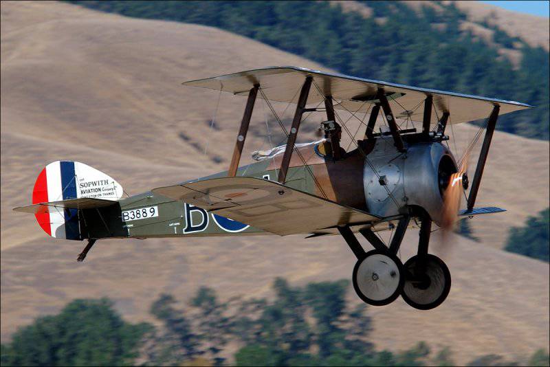
Very characteristic in this regard was the famous Sopwith Camel F.1 Royal Air Force aircraft, which was considered the best fighter of the First World War. On it stood the rotary engine Clerget 9B (as a note I will add that later the English Bentley BR.1 (150 hp) was also put). Powerful (130 hp), but rather capricious engine, sensitive to the composition of the fuel and to the oil. Could easily refuse to take off. But it was thanks to him and the features of the layout of the fuselage (the dispersal of useful equipment) Camel was very maneuverable.

This maneuverability, however, reached an extreme. In the management of the fighter was unusually strict and generally had some unpleasant features. For example, a great desire to enter the spin at low speed :-). He was absolutely not suitable for training young pilots. According to some statistics, 415 pilots died during the war in the fighting on this airplane, and 385 died in flight accidents. The figures are eloquent ...
However, experienced pilots who mastered it well could benefit greatly from its features and did it. Interestingly, due to Camel's reluctance to turn quickly to the left, many pilots preferred to do this, so to speak, “through the right shoulder” :-). Turning right to 270º was much faster than turning left to 90º.
The main and worthy opponent for Sopwith Camel F.1 was the German Fokker Dr.I triplane with the engine Oberursel UR.II (full analogue of the French Le Rhône 9J). Baron Manfred Albrecht von Richthofen (Manfred Albrecht Freiherr von Richthofen), the famous “Red Baron” fought on such a war.

During the war, rotary engines reached its full bloom. With the existing demands of the army, despite their shortcomings, they were very well suited for solving, so to speak, the triple task of “power - weight - reliability”. Especially with regard to light fighters. After all, the overwhelming majority of these engines were on them.
Larger and heavier planes continued to fly using traditional in-line engines.
However, aviation developed at a rapid pace. More and more engine power was required. For stationary line-ups, this was achieved by increasing the maximum number of turns. Opportunities for improvement in this direction were. Improved ignition and gas distribution systems, the principles of formation of the air-fuel mixture. More and more advanced materials were used.
This allowed by the end of the First World War to raise the maximum speed of the stationary engine from 1200 to 2000 rpm.
However, for a rotary engine this was not possible. To organize the correct blending was impossible. Everything had to be done "by eye", so the fuel consumption (as well as oil) was, to put it mildly, rather big :-) (including, by the way, due to constant work at high speeds).
Any external adjustment work on the engine, while it is in disrepair, was by itself impossible.
It was also impossible to increase the rotational speed, because the air resistance to the rapidly rotating cylinder block was large enough. Moreover, with increasing rotation speed, the resistance grew even faster. After all, as is known, the velocity head is proportional to the square of the velocity (ρV2 / 2, where ρ is the air density, V is the flow velocity). That is, if the speed simply increases, then the resistance grows in a square (approximately :-)).
When trying on some engine models of the beginning of the war to raise the speed from 1200 r / min to 1400 r / min, the resistance rose by 38%. That is, it turned out that the increased engine power was spent more on overcoming resistance than on creating useful propeller thrust.
The German company Siemens AG attempted to get around this problem from a different angle. The 11-cylinder engine of the so-called biotective scheme (name Siemens-Halske Sh.III) was manufactured. In it, the cylinder block rotated in one direction with a frequency of 900 rpm, and the shaft (previously fixed) in the other with the same frequency. The total relative frequency was 1800 rpm. This made it possible to achieve power in the 170 HP.
This engine had less resistance to air during rotation and less torque that interfered with control. Installed on the Siemens-Schuckert D.IV fighter, which, according to many experts, has become one of the best maneuverable fighters of the war. However, it began to be produced late and was made in a small number of copies.
The existing situation of Siemens-Halske Sh.III did not correct and could not again lift rotary engines to the proper height.
As you can see, they have enough flaws. Everything else, I can still add that these engines were quite expensive. After all, due to the large rapidly rotating mass, all engine parts had to be well balanced and well adjusted. Plus the materials themselves were not cheap. This led to the fact that, for example, the Monosoupape engine at 1916 prices of the year was worth about 4000 $ (which translates into 2000 of the year, about 65000 $). This is despite the fact that in the engine, in general, according to current concepts :-), there is nothing special.
In addition, the lifespan of all such engines was low (up to 10 hours between repairs) and they had to be changed often, despite the high cost.
All these shortcomings accumulated and in the end the bowl was overflowing. The rotative engine was widely used and improved (as far as possible) until the end of the war. Airplanes with such engines were used for some time during the civil war in Russia and foreign intervention. But in general, their popularity quickly declined.
The improvement of science and production led to the fact that a follower of a rotary engine stepped onto the scene - an air-cooled radial or star-shaped engine that does not descend from it to this day, working, by the way, in collaboration with a liquid-cooled in-line reciprocating aircraft engine .
The rotative engine, leaving a bright mark in the history of aviation, now occupies an honorable place in museums and at historical exhibitions.
At this end :-). In conclusion, as always, some interesting video. The first video - the launch of the restored engine Gnome 1918 year of release. Then three videos about the engine and the flights of the restored Sopwith Camel F.1, as well as Fokker Dr.I (in the background :-)). Interesting to see you and see you ...
PS One of my readers (Alexander) quite rightly pointed out to me that in the video, where the modern replica of the German triplan is flying along with Sopvich, the engine of this triplane is not rotary. Absolutely right. I, fascinated by Sopvich, did not pay attention to it :-). I apologize to the readers and put the video (and photo), where in flight a modern Fokker replica with a real rotary engine. The plane here is cool shown :-) ...

Sopwith Camel F.1 fighter with a Clerget 9B engine.
The basic principles of aircraft and engine-building quickly took a steady shape. There were more and more models of engines for airplanes, and with them both new victories and new problems in the engine industry. Designers and engineers sought (as it is, in general, is happening now :-)) to maximally facilitate the engines and at the same time maintain or even increase their traction efficiency.
On this wave, a rotated engine appeared for the then airplanes. Why for airplanes? Because by itself this type of engine was developed even much earlier than the first flight of the Wright brothers.
But first things first. What is a rotary engine ... In English, the rotary engine (which, by the way, in my opinion is strange, because the same word denotes a rotary engine (Wankel engine)). This is an internal combustion engine in which cylinders with pistons (their odd number) are located radially in the form of a star, usually four-stroke.
Working fuel - gasoline, ignition comes from the spark plugs.
In appearance, it is very similar to the well-known radial (star-shaped) piston engine that appeared almost simultaneously with it and well today. But this is only in a non-working state. When you start a rotary engine on a person who is ignorant of him makes a strong impression.
Rotational engine operation.
This happens because his work looks very unusual at first glance. Indeed, together with the screw rotates and the entire cylinder block, that is, in fact, the whole engine. And the shaft on which this rotation takes place is fixed. However, in mechanical terms, there is nothing unusual here. Just a matter of habit :-).
The fuel-air mixture due to the rotation of the cylinders cannot be supplied to them in the usual manner; therefore, it gets there from the crankcase, where it is fed through a hollow shaft from the carburetor (or its replacement device).
For the first time in stories A patent for the rotary engine was obtained by the French inventor Félix Millet in 1888. Then they put this engine on a motorcycle and showed it at the Paris World Exhibition in 1889.
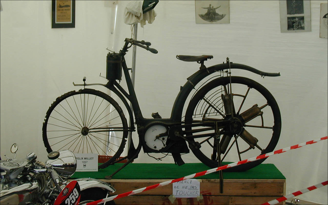
Rotational motor Félix Millet on a motorcycle.
Later, Félix Millet engines were installed on cars, one of which took part in the world's first Paris – Bordeaux – Paris car race in 1895, and since 1900, these engines were put on cars by the French company Darracq.
In the future, engineers and inventors began to pay attention to the rotary engine from the point of view of its use in aviation.
The first in this regard was Stephen Balzer, a former New York watchmaker, who created his rotary engine in 1890 and became the author (with engineer Charles M. Manly) of the first ever engine developed specifically for an airplane known as the Manly-Balzer engine.
Almost simultaneously, he worked with the American engineer Adams Farwell, who built cars with rotary engines from 1901 of the year.
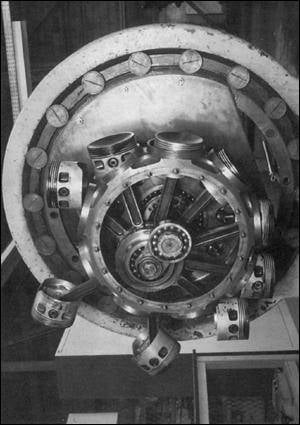
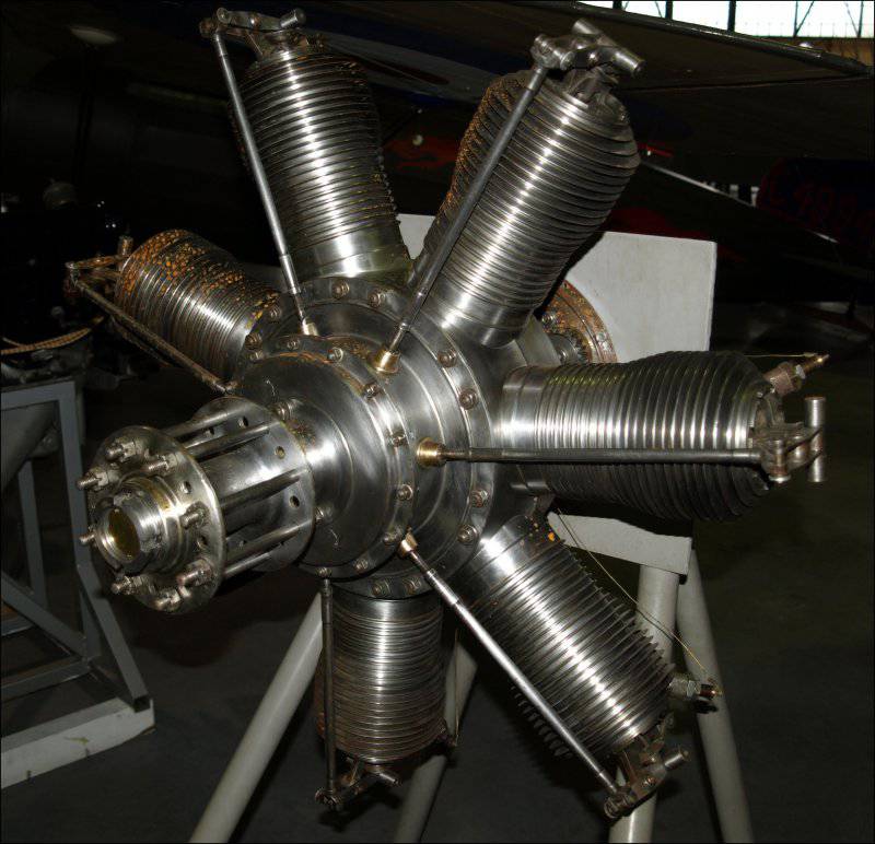
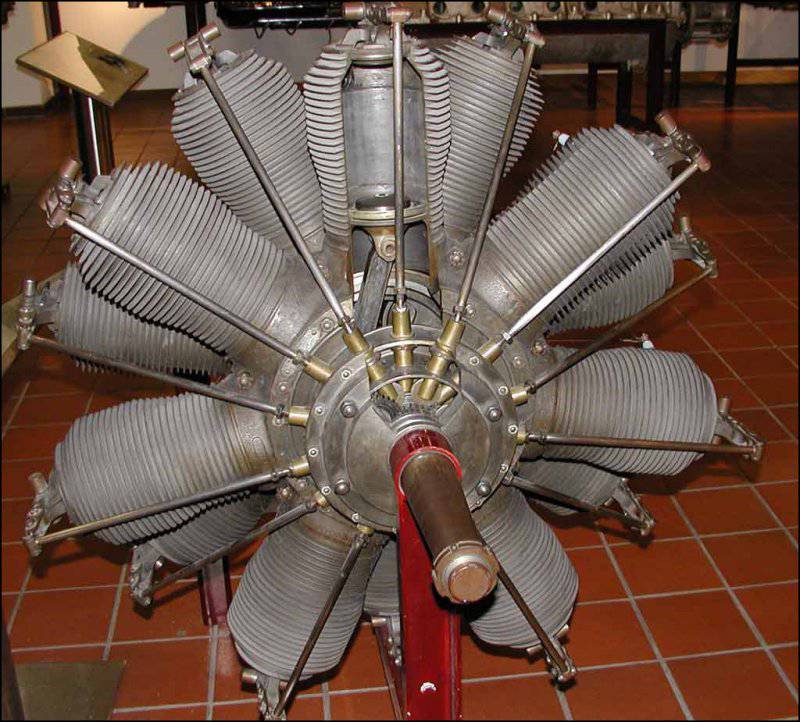
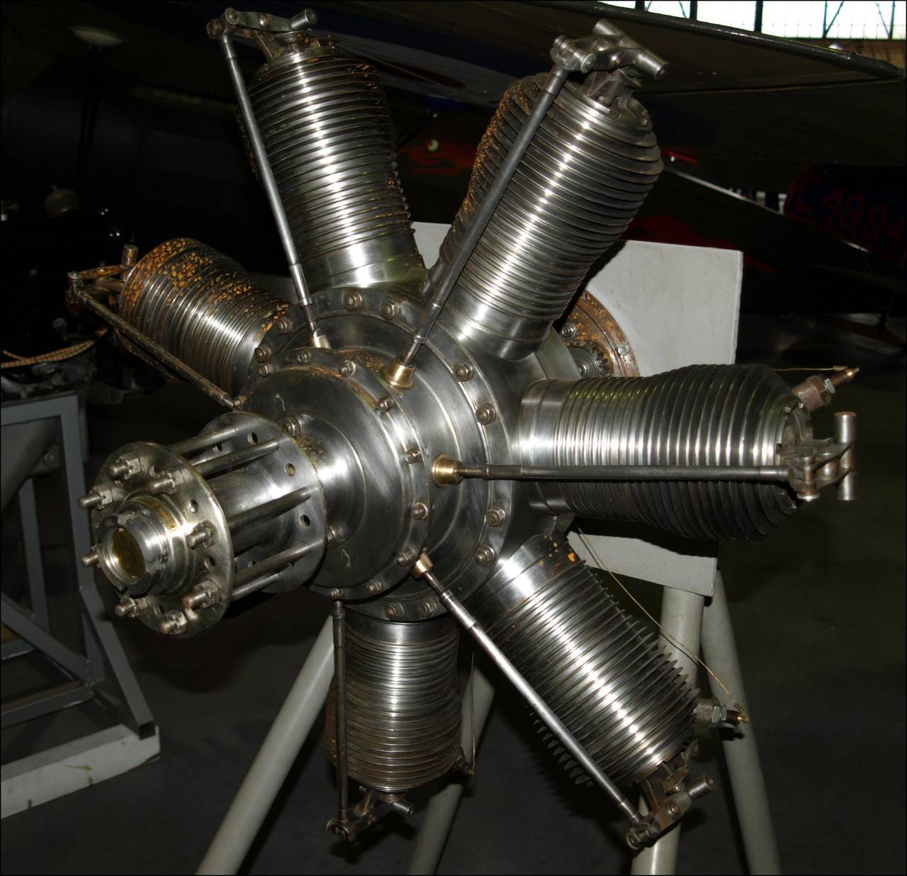
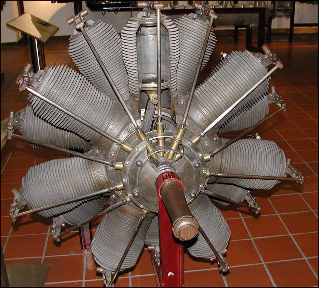
Open engine crankcase Le Rhône 9J.
According to some information, the principles of the design of its engines were taken as a basis by the manufacturers of the subsequently famous Gnome engines.
What was it that attracted engineers in a rotary engine? What is so useful for aviation?
There are two main features that are its main positive qualities. The first is the smallest (at that time) weight compared with engines of the same power. The fact is that the rotational speeds of the then engines were low and to obtain the required power (on average, then, of the order of 100 hp (75 kW)), the ignition cycle of the air-fuel mixture made itself felt by very tangible jolts.
To avoid this, the engines were supplied with massive flywheels, which naturally entailed a heavier structure. But for a rotary engine, the flywheel was not needed, because the engine itself was spinning, having enough mass to stabilize the stroke.
Such engines differed smoothness and uniformity. The ignition was made sequentially in each cylinder through one in a circle.
The second feature was good cooling. The metallurgical industry in those days was not as developed as it is now and the quality of the alloys (in terms of heat resistance) was not too high. Therefore, good cooling was required.
Aircraft flight speeds were not high, so simple cooling with the oncoming flow of a stationary engine was insufficient. And the rotary engine here was in a more advantageous position, because it itself rotated with sufficient speed for effective cooling and the cylinders were blown well by air. At the same time, they could be both smooth and ribbed. Cooling was quite effective even when the engine was running on the ground.
Now let's digress for a couple of useful videos about the work of a rotary engine. The first is the modeling of his work on the computer. The second shows the work of the “insides” of the engine Le Rhône.
The flowering of rotary engines fell on the First World War. At that time, aviation was already seriously involved in hostilities and air battles were not uncommon. Airplanes and engines for them were made by all major participants in the war.
Of the engine-building systems, one of the most famous was the French firm Société des Moteurs Gnome, which was once engaged in the production of internal combustion engines for industrial production. In 1900, she bought a license to manufacture a small single-cylinder stationary engine (horsepower 4) Gnom from the German company Motorenfabrik Oberursel. This engine was sold in France under the French name Gnome and so successfully that the name was used in the name of the company.
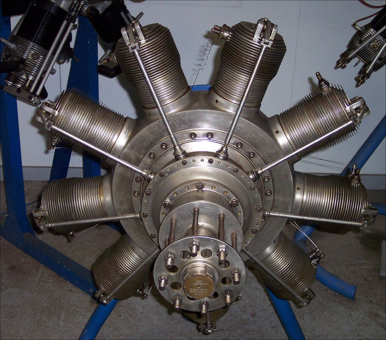
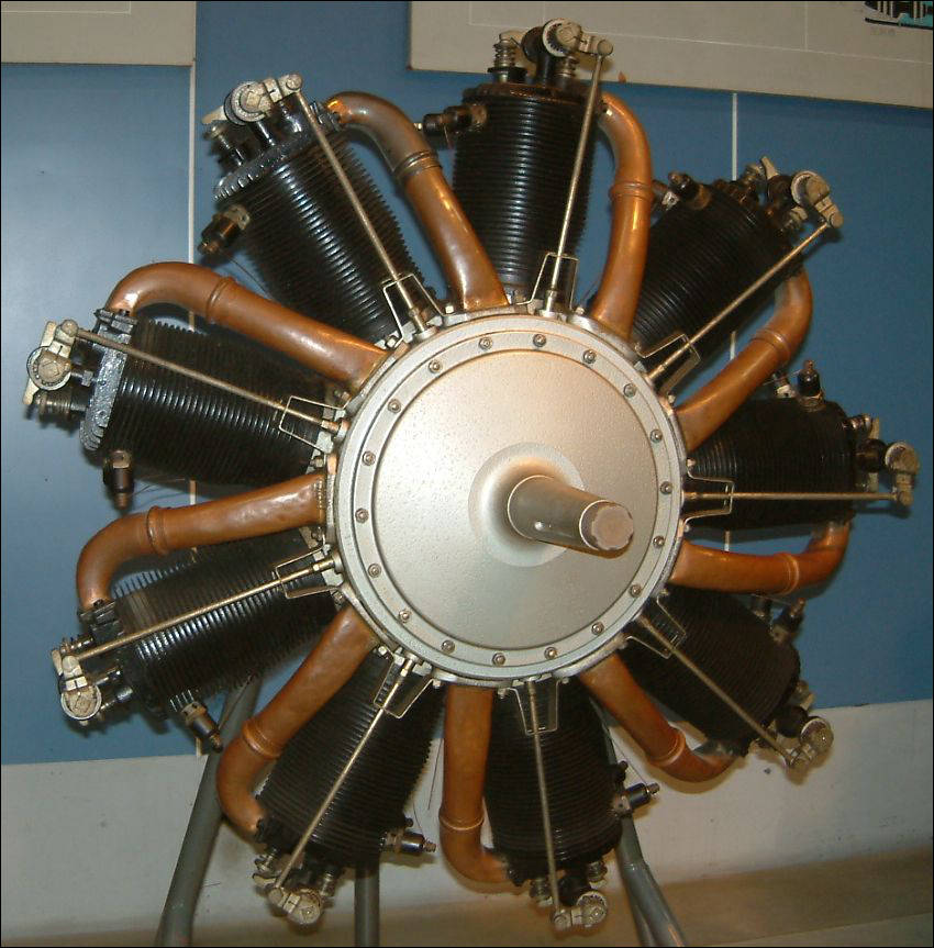
Rotational engine Gnome 7 Omega.
Later on the basis of the Gnome was developed rotary engine Gnome Omega, which had a considerable number of modifications and was installed on a variety of aircraft. There are also other massively produced engines of this company. For example, the Gnome 7 Lambda - seven-cylinder, horsepower 80 hp and its continuation Gnome 14 Lambda-Lambda (160 hp), a two-row rotary engine with 14-th cylinders.
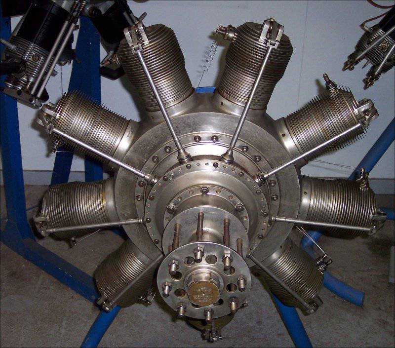
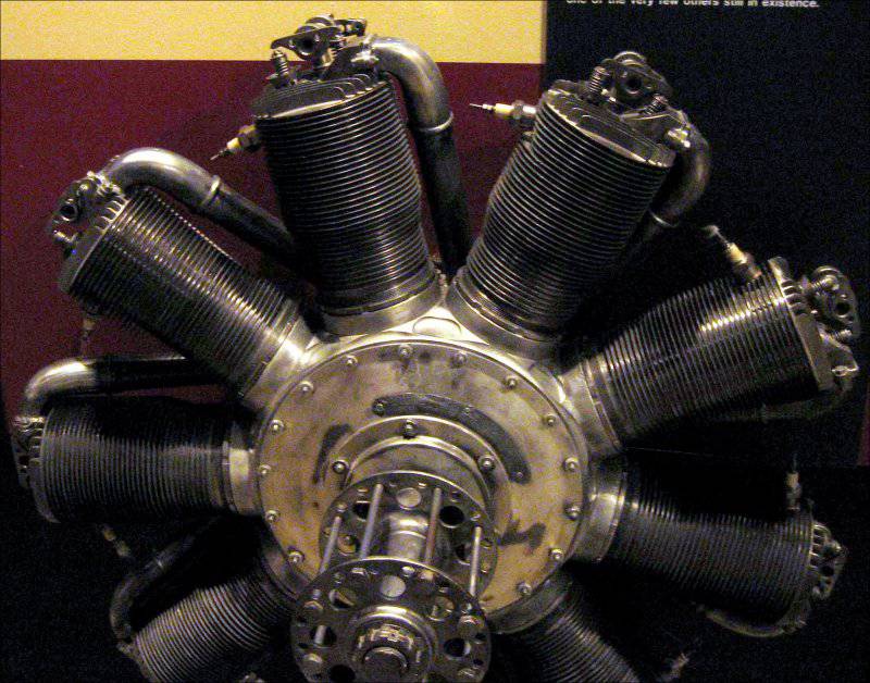
Engine Gnome Monosoupape.
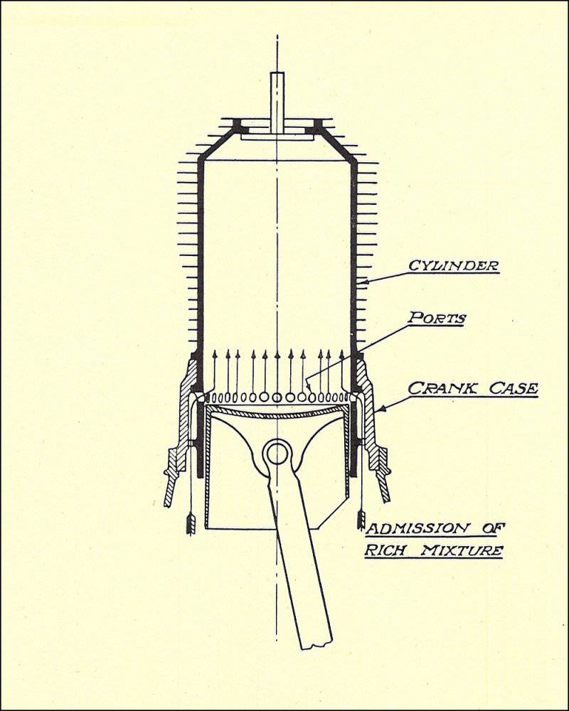
The Gnome Monosoupape engine (one valve) is widely known, it was launched in the 1913 year and was considered one of the best engines in the initial period of the war. This “best engine” :-) had only one valve used for both exhaust and air intake. For the flow of fuel into the cylinder from the crankcase, a number of special holes were made in the cylinder skirt. The engine was beskarbyutorny and because of the simplified control system was lighter and consumed, besides less oil.

Fuel supply to the Gnome Monosoupape cylinder. Crank Case - crankcase, Ports - supply holes.
He had practically no control. There was only a fuel valve that fed gas through a special nozzle (or sprayer) into the hollow fixed shaft and then into the crankcase. This crane could try to enrich or deplete the air-fuel mixture in a very narrow range, which was of little use.
They tried to use for the purpose of control the change in valve timing, but they quickly refused to do this, because the valves began to burn. As a result, the engine constantly worked at maximum speed (as, by the way, all rotary engines :-)) and was controlled only by turning off the ignition (more on that below :-)).
Another well-known French company producing rotary engines was Société des Moteurs Le Rhône, which began its work with 1910. One of its most famous engines was Le Rhône 9C (power 80 hp) and Le Rhône 9J (110 hp). Their characteristic feature was the presence of special pipelines from the crankcase to the cylinders for supplying the fuel-air mixture (a bit like the inlet manifolds of modern internal combustion engines).
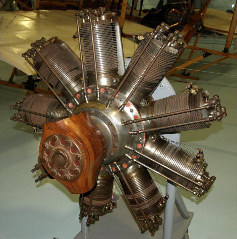
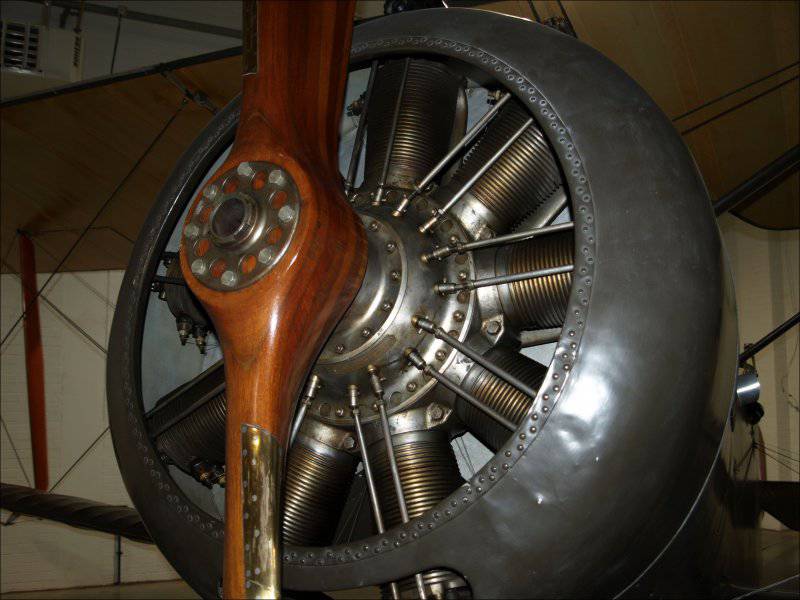
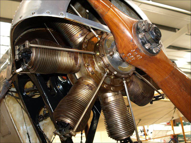
Engine Le Rhone 9C.

Le Rhone 9J rotary motor.
Le Rhône and Gnome initially competed, but then merged and with 1915, they already worked together under the name Société des Moteurs Gnome et Rhône. The 9J engine was, in general, already their joint product.
Interestingly, the aforementioned German company Motorenfabrik Oberursel in 1913 purchased licenses for the production of the now French rotary Gnome engines (although it was the ancestor of this brand, you can say :-)) and a little later the Le Rhône engines. She released them under her own names: Gnome, like the U-series and Le Rhône, as the UR-series (from the German word Umlaufmotor, meaning a rotary engine).
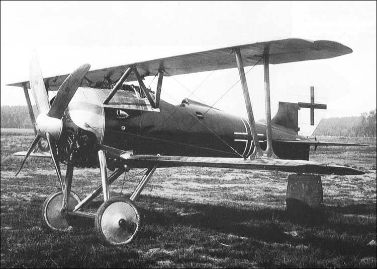
For example, the Oberursel U.0 engine was similar to the French Gnome 7 Lambda and was installed initially on the Fokker EI aircraft, and the Oberursel U.III engine is a copy of the two-row Gnome 14 Lambda-Lambda.
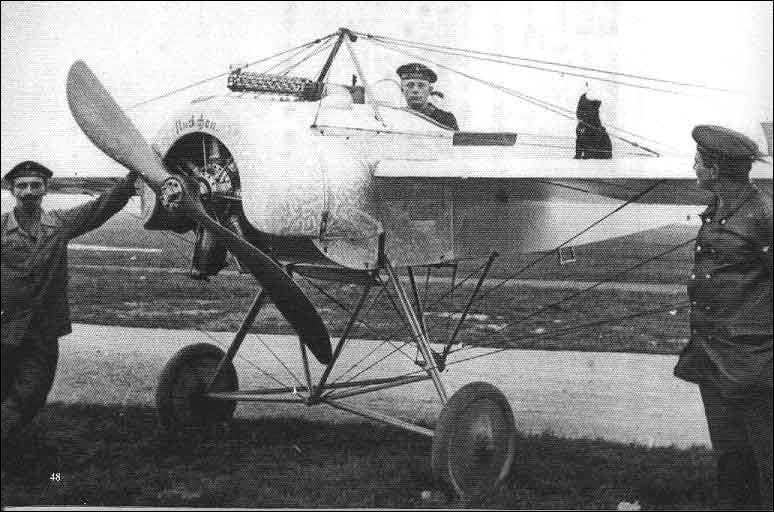
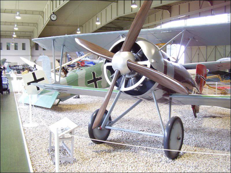
Fokker EI fighter with an Oberursel U.0 engine.
German double row Oberursel U.III, copy of Gnome 14 Lambda-Lambda.
In general, the company Motorenfabrik Oberursel throughout the war produced quite a large number of clone engines of French models, which were then put on airplanes that were opponents of the French and their allies in aerial combat. These are the tricks of life :-) ...
Among other well-known engine-building companies, the French company Société Clerget-Blin et Cie (the word Blin interesting for the Russian ear in the name means the name of one of the founders, industrialist Eugene Blin :-)) is also listed with its famous Clerget 9B engine.

Engine Clerget 9B.

Clerget 9B engine on a Sopwith 1½ Strutter fighter.
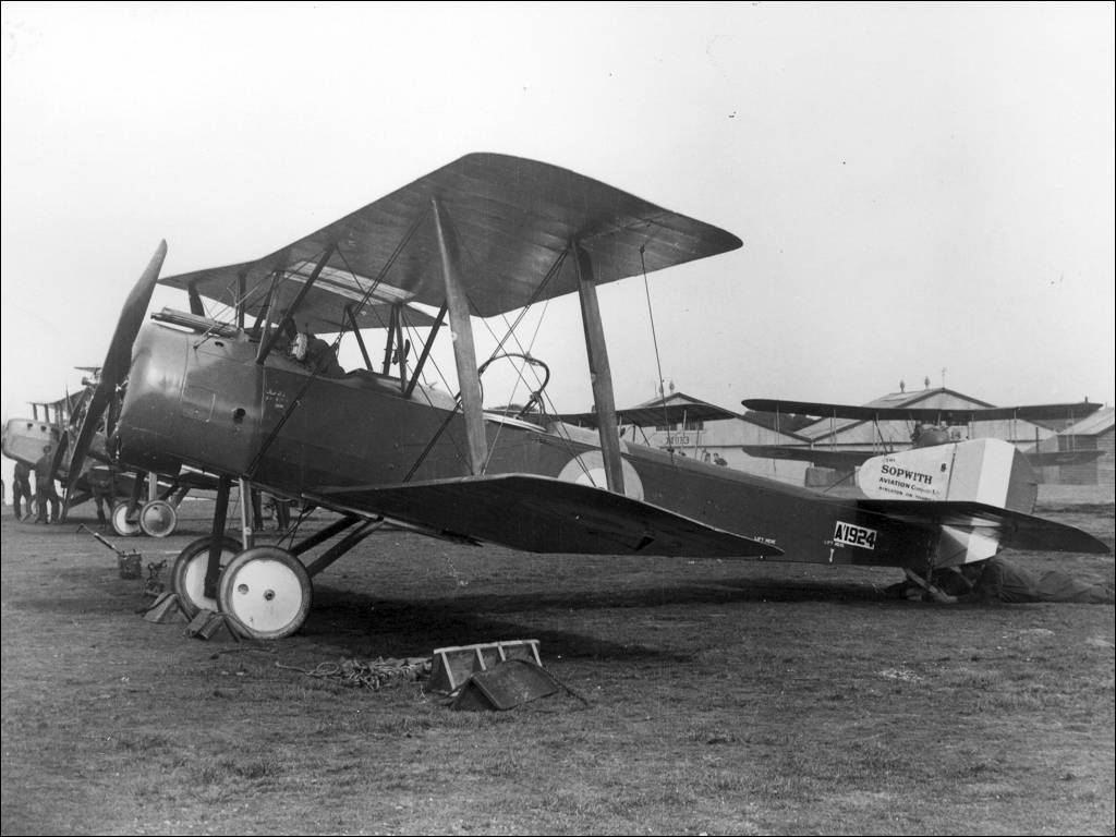
Sopwith 1 1 / 2 Strutter fighter with a Clerget 9B engine.
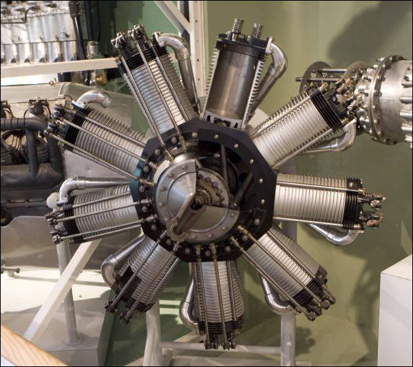
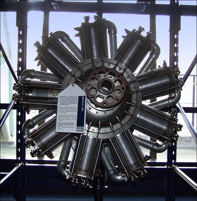
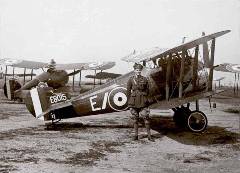
Many engines were manufactured in the UK under licenses. The same factories produced the British engines developed by Walter Owen Bentley (the same Bentley) Bentley BR.1 (replacing the Clerget 9B on the Sopwith Camel) and Bentley BR.2 for the Sopwith 7F.1 Snipe fighter.
On the Bentley engines in the design of the pistons were first used aluminum alloys. Prior to this, all engines had cast-iron cylinders.
Bentley BR1 rotary engine.
Bentley BR2 rotary engine.
Sopwith 7F.1 Snipe Fighter with Bentley BR.2 Engine
Now let us remember about other features of the rotary engine, which, so to speak, do not add benefits to it :-) (most often just the opposite).
A little about management. A modern (stationary, of course :-)) piston engine, whether it is inline or star-shaped, is relatively easy to control. The carburetor (or injector) forms the desired composition of the fuel-air mixture and with the help of the throttle the pilot can regulate its flow to the cylinders and, thus, change the engine speed. To do this, in essence, there is a handle (or pedal, as you wish :-)) gas.
With a rotary engine, things are not so simple :-). Despite the difference in design, most of the rotary engines had a controlled intake valve on the cylinders, through which the fuel-air mixture entered. But the rotation of the cylinders did not allow the use of a conventional carburetor, which would support the optimal air-fuel ratio behind the throttle valve. The composition of the mixture entering the cylinders had to be adjusted to achieve the optimum ratio and stable engine performance.
For this, there was usually an additional air valve (“bloctube”). The pilot set the throttle lever to the desired position (often opening the throttle completely) and then using the air supply adjustment lever, he achieved stable engine operation at maximum speed, producing the so-called fine adjustment. At such speeds, and usually passed the flight.
Due to the large inertia of the engine (the mass of the cylinders is nevertheless rather big :-)), such adjustment was often done using the “spear method”, that is, it was possible to determine the desired amount of adjustment only in practice, and this practice was necessary for confident control. Everything depended on the engine design and pilot experience.
The entire flight took place at the maximum engine speed, and if for any reason it was necessary to reduce it, for example, to land, the control actions should be in the opposite direction. That is, the pilot had to close the throttle and then regulate the air supply to the engine again.
But such a “control” was, as you understand, rather cumbersome and time consuming, which is not always in flight, especially during landing. Therefore, the ignition shutdown method was used more often. Most often this was done through a special device that allows you to turn off the ignition completely or in separate cylinders. That is, the cylinders without ignition stopped working and the engine as a whole was losing power, which was what the pilot needed.
This method of management was widely used in practice, but it dragged along a lot of problems. Fuel, together, by the way, with oil, despite the ignition off, continued to flow into the engine and, unburntly, safely left it and then accumulated under the hood. Since the engine is very hot, there is a danger of a serious fire. The then "light bookshelves" burned very easily and quickly :-).

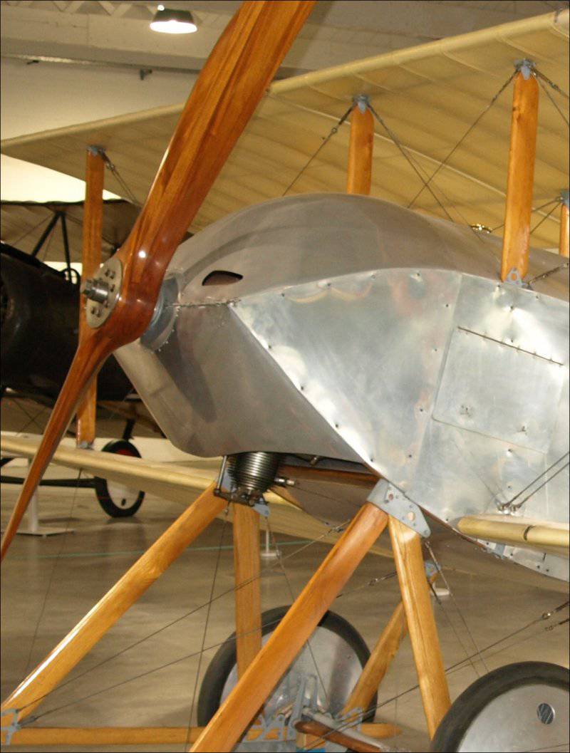
An example of a protective engine hood (engine oil protection Gnome 7 Lambda) on a Sopwith Tabloid aircraft.
Therefore, engine hoods had a cut-out at about one third of the perimeter, or at worst serious drainage taps, so that all this filth could be removed by the oncoming flow. Most often, of course, she smeared on the fuselage.
In addition, candles in non-operating cylinders could be flooded and oily and restarting was therefore not guaranteed.
By 1918, the French engine company Société Clerget-Blin et Cie (Clerget 9B rotary engines), based on the apparent danger of using a power reduction method by turning off the ignition, the following control method was recommended in the engine manual.
If it is necessary to reduce the engine's power, the pilot shuts off the fuel supply by closing the throttle (with the throttle). In this case, the ignition does not turn off, and the candles continue to “spark” (protecting themselves from oiling). The screw rotates as a result of the autorotation effect, and if it is necessary to start the fuel valve, it simply opens into the same position as before closing. The engine starts ...
However, according to pilots, who fly today on reconstructed or replicas of aircraft of that time, the most convenient mode of reducing power is still turning off the ignition, despite all the “dirt” that rotary engines eject :-).
Airplanes with such engines in general did not differ in high purity. I already said about the fuel in the disconnected cylinders, but there was also oil. The fact is that due to the rotating cylinder block, the possibility of pumping fuel from the crankcase was very problematic, so it was impossible to organize a full-fledged lubrication system.
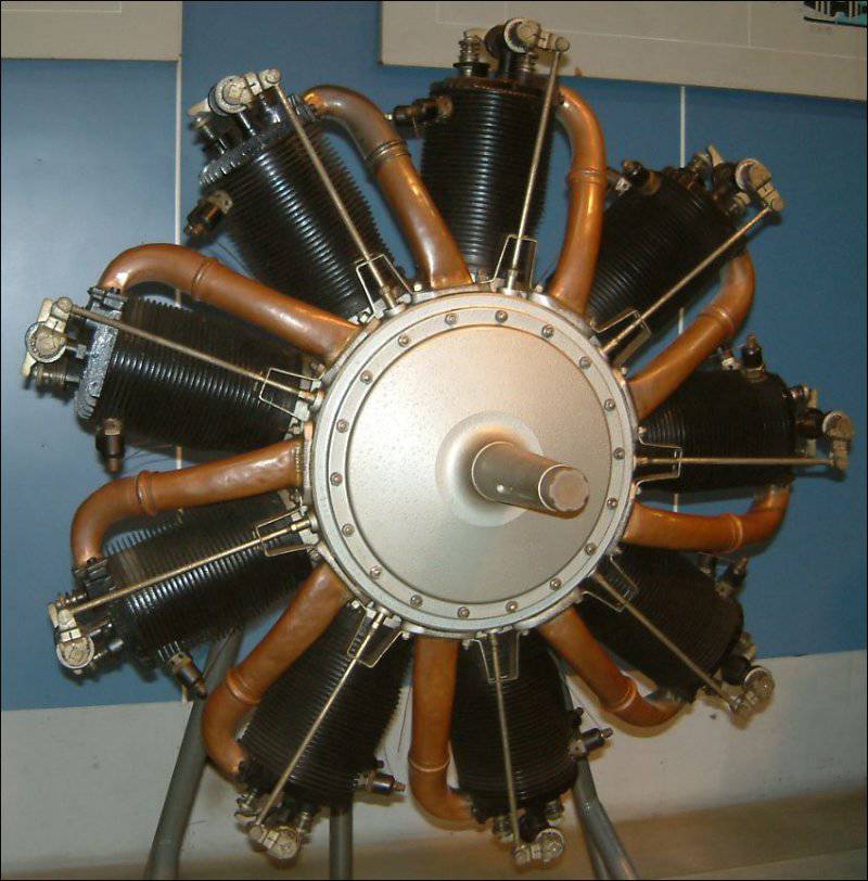
Scheme of fuel and oil supply rotary engine Gnome 7 Omega.
But without lubrication, no mechanism will work, so it, of course, existed, but in oh-oh-very simplified form. Oil was supplied directly to the cylinders, to the fuel-air mixture. On most engines, there was a small pump for this, which fed oil through a hollow (fixed, as already known :-)) shaft through special channels.
As a lubricating oil, castor oil was used, the best in those times (natural vegetable oil) for these purposes. It also did not mix with fuel, which improved lubrication conditions. Yes, and burned in the cylinders, it is only partially.

An example of oiling (dark spots) engine Gnome 7 Omega semi-burnt castor oil.
And it was removed from there after performing its functions together with the exhaust gases through the exhaust valve. And the expense of it at the same time was very rather big. Medium engine, about 100 horsepower (≈75 kW, 5-7 cylinders) for an hour of work spent more than two gallons (English) oils. That is, about 10 liters flew "to the wind."
Well what can I say ... Poor mechanics :-). The oil that burned out and not quite, the fuel mixture remaining after throttling the engine, soot ... it all settled on the plane, and all that had to be washed. And the oil is washed out very badly. Because of this, in old photographs, airplanes often “flaunt” dirty spots on the wing and fuselage.
But the pilots are courageous people :-). After all, out of the engine castorca. And this, as you know, is a very good laxative (it was sold in pharmacies before, I don’t know how it is now). Of course, the engine was closed by the hood, and from the bottom, as I said, there was a cut-out for removing all the dirt. But the cabin is open and the air flow is not always controlled. If pure castorca fell on the face and then inside ... Consequences to predict .... it was probably not difficult :-) ...
The next feature of the rotary engines, which I also would not call positive, was related to the controllability of the airplanes on which such engines stood. The large mass of the rotating block was in fact a large gyroscope, so the gyroscopic effect was inevitable :-).
While the plane was flying straight, its influence was not very noticeable, but as soon as it began to make any flight evolutions, the gyroscopic precession immediately manifested itself. Because of this, and coupled with a large torque of a massive block of cylinders, the aircraft turned very reluctantly to the left while raising its nose, but quickly turned right, with a large tendency to lower the nose.
This effect, on the one hand, was very disturbing (especially to young and inexperienced pilots), and on the other hand, it was useful during air battles, in the so-called dogfights. This, of course, for experienced pilots who could really use this feature.
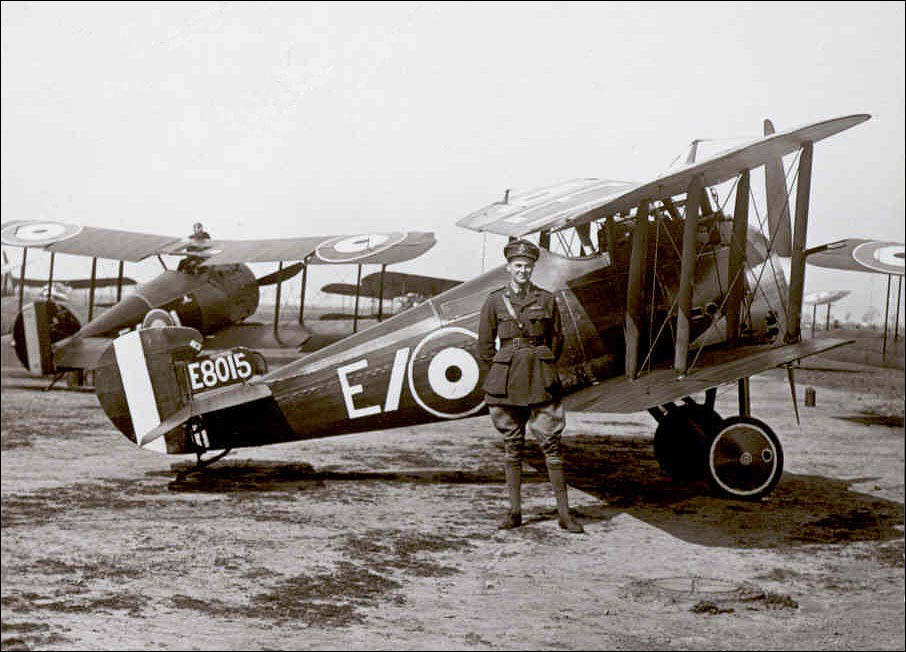
Very characteristic in this regard was the famous Sopwith Camel F.1 Royal Air Force aircraft, which was considered the best fighter of the First World War. On it stood the rotary engine Clerget 9B (as a note I will add that later the English Bentley BR.1 (150 hp) was also put). Powerful (130 hp), but rather capricious engine, sensitive to the composition of the fuel and to the oil. Could easily refuse to take off. But it was thanks to him and the features of the layout of the fuselage (the dispersal of useful equipment) Camel was very maneuverable.

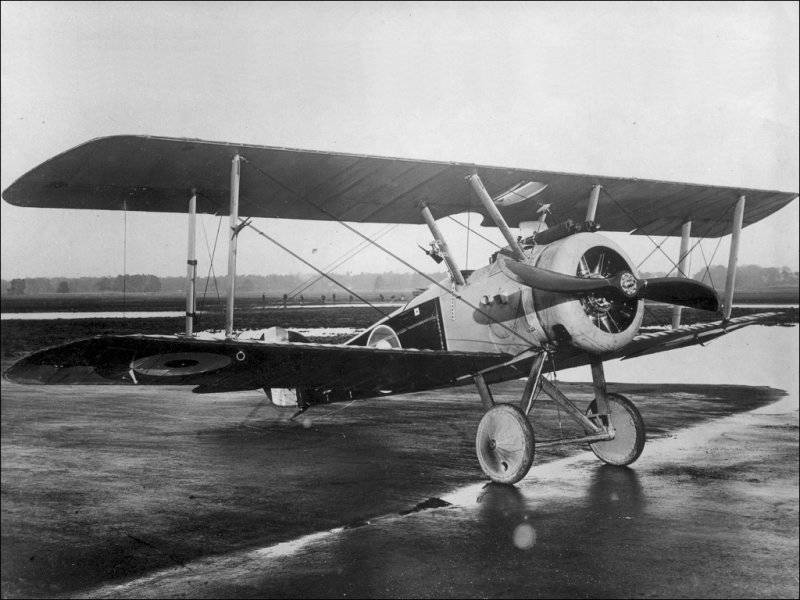
Sopwith Camel F.1 fighter with a Clerget 9B engine.

Fighter Sopwith Camel F.1 (replica).
This maneuverability, however, reached an extreme. In the management of the fighter was unusually strict and generally had some unpleasant features. For example, a great desire to enter the spin at low speed :-). He was absolutely not suitable for training young pilots. According to some statistics, 415 pilots died during the war in the fighting on this airplane, and 385 died in flight accidents. The figures are eloquent ...
However, experienced pilots who mastered it well could benefit greatly from its features and did it. Interestingly, due to Camel's reluctance to turn quickly to the left, many pilots preferred to do this, so to speak, “through the right shoulder” :-). Turning right to 270º was much faster than turning left to 90º.
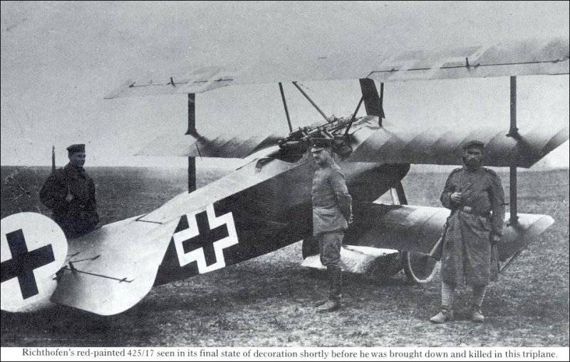
The main and worthy opponent for Sopwith Camel F.1 was the German Fokker Dr.I triplane with the engine Oberursel UR.II (full analogue of the French Le Rhône 9J). Baron Manfred Albrecht von Richthofen (Manfred Albrecht Freiherr von Richthofen), the famous “Red Baron” fought on such a war.
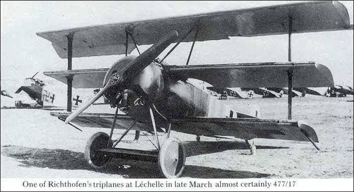
Triplan Fokker Dr.I

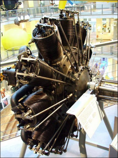
German engine Oberursel-UR-2. Copy of Le Rhône 9J.
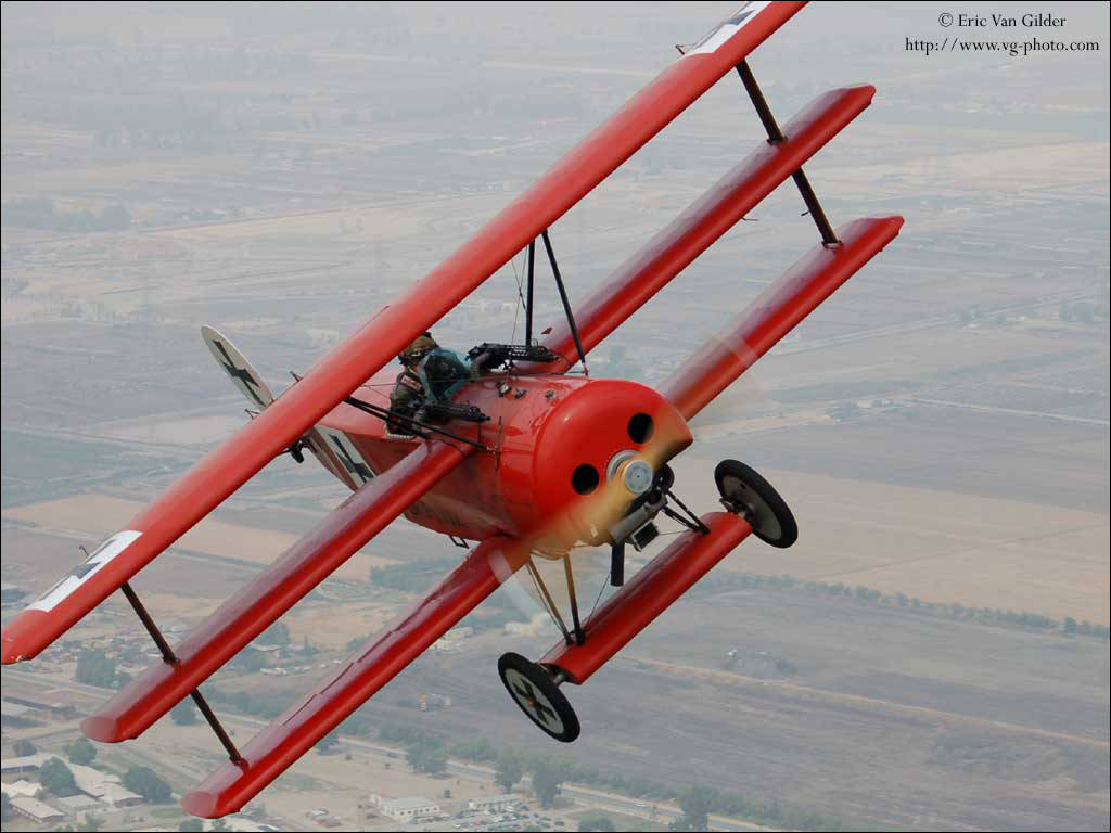
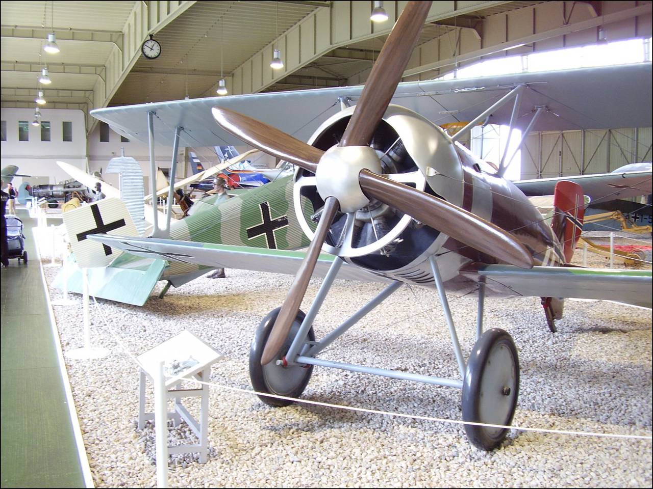
The Fokker Dr.I triplane fighter (modern replica, though the engine is not rotary).
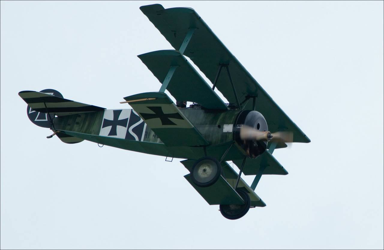
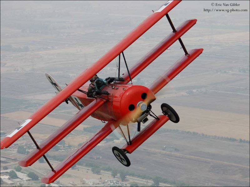
Fokker DR1, a modern replica with a true rotary engine.
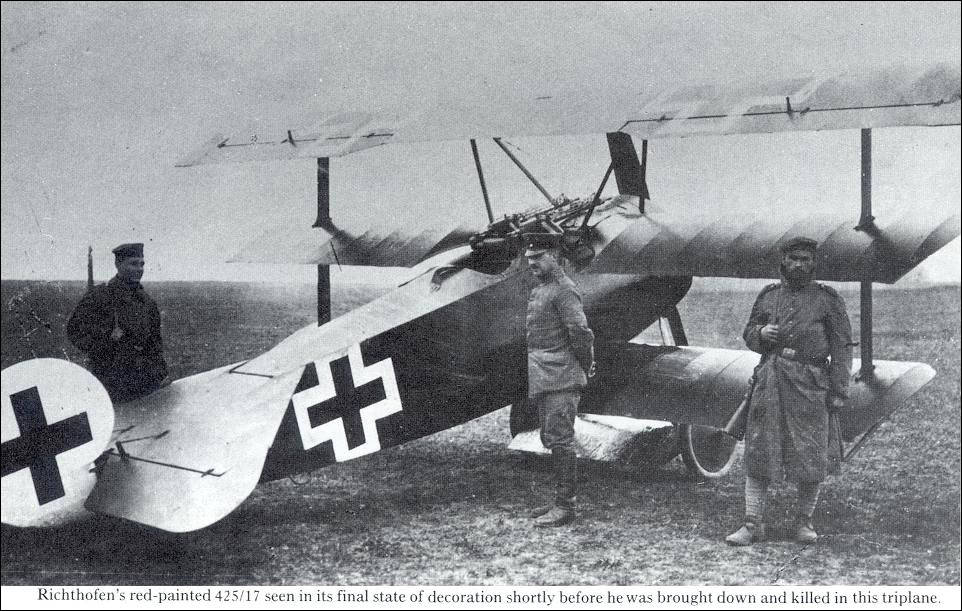
Triplan Fokker Dr.I shortly before the death of the "Red Baron".
During the war, rotary engines reached its full bloom. With the existing demands of the army, despite their shortcomings, they were very well suited for solving, so to speak, the triple task of “power - weight - reliability”. Especially with regard to light fighters. After all, the overwhelming majority of these engines were on them.
Larger and heavier planes continued to fly using traditional in-line engines.
However, aviation developed at a rapid pace. More and more engine power was required. For stationary line-ups, this was achieved by increasing the maximum number of turns. Opportunities for improvement in this direction were. Improved ignition and gas distribution systems, the principles of formation of the air-fuel mixture. More and more advanced materials were used.
This allowed by the end of the First World War to raise the maximum speed of the stationary engine from 1200 to 2000 rpm.
However, for a rotary engine this was not possible. To organize the correct blending was impossible. Everything had to be done "by eye", so the fuel consumption (as well as oil) was, to put it mildly, rather big :-) (including, by the way, due to constant work at high speeds).
Any external adjustment work on the engine, while it is in disrepair, was by itself impossible.
It was also impossible to increase the rotational speed, because the air resistance to the rapidly rotating cylinder block was large enough. Moreover, with increasing rotation speed, the resistance grew even faster. After all, as is known, the velocity head is proportional to the square of the velocity (ρV2 / 2, where ρ is the air density, V is the flow velocity). That is, if the speed simply increases, then the resistance grows in a square (approximately :-)).
When trying on some engine models of the beginning of the war to raise the speed from 1200 r / min to 1400 r / min, the resistance rose by 38%. That is, it turned out that the increased engine power was spent more on overcoming resistance than on creating useful propeller thrust.
The German company Siemens AG attempted to get around this problem from a different angle. The 11-cylinder engine of the so-called biotective scheme (name Siemens-Halske Sh.III) was manufactured. In it, the cylinder block rotated in one direction with a frequency of 900 rpm, and the shaft (previously fixed) in the other with the same frequency. The total relative frequency was 1800 rpm. This made it possible to achieve power in the 170 HP.
Birotative Siemens-Halske Sh. III engine.
Fighter Siemens-Schuckert D.IV.
Siemens-Schuckert D.IV fighter in the Berlin Museum.
This engine had less resistance to air during rotation and less torque that interfered with control. Installed on the Siemens-Schuckert D.IV fighter, which, according to many experts, has become one of the best maneuverable fighters of the war. However, it began to be produced late and was made in a small number of copies.
The existing situation of Siemens-Halske Sh.III did not correct and could not again lift rotary engines to the proper height.
As you can see, they have enough flaws. Everything else, I can still add that these engines were quite expensive. After all, due to the large rapidly rotating mass, all engine parts had to be well balanced and well adjusted. Plus the materials themselves were not cheap. This led to the fact that, for example, the Monosoupape engine at 1916 prices of the year was worth about 4000 $ (which translates into 2000 of the year, about 65000 $). This is despite the fact that in the engine, in general, according to current concepts :-), there is nothing special.
In addition, the lifespan of all such engines was low (up to 10 hours between repairs) and they had to be changed often, despite the high cost.
All these shortcomings accumulated and in the end the bowl was overflowing. The rotative engine was widely used and improved (as far as possible) until the end of the war. Airplanes with such engines were used for some time during the civil war in Russia and foreign intervention. But in general, their popularity quickly declined.
The improvement of science and production led to the fact that a follower of a rotary engine stepped onto the scene - an air-cooled radial or star-shaped engine that does not descend from it to this day, working, by the way, in collaboration with a liquid-cooled in-line reciprocating aircraft engine .
The rotative engine, leaving a bright mark in the history of aviation, now occupies an honorable place in museums and at historical exhibitions.
At this end :-). In conclusion, as always, some interesting video. The first video - the launch of the restored engine Gnome 1918 year of release. Then three videos about the engine and the flights of the restored Sopwith Camel F.1, as well as Fokker Dr.I (in the background :-)). Interesting to see you and see you ...
PS One of my readers (Alexander) quite rightly pointed out to me that in the video, where the modern replica of the German triplan is flying along with Sopvich, the engine of this triplane is not rotary. Absolutely right. I, fascinated by Sopvich, did not pay attention to it :-). I apologize to the readers and put the video (and photo), where in flight a modern Fokker replica with a real rotary engine. The plane here is cool shown :-) ...
Information