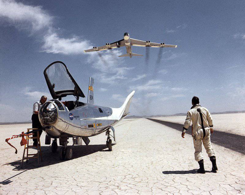
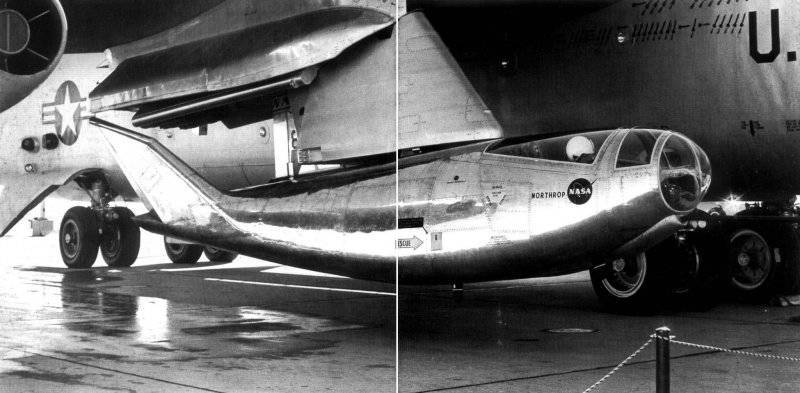
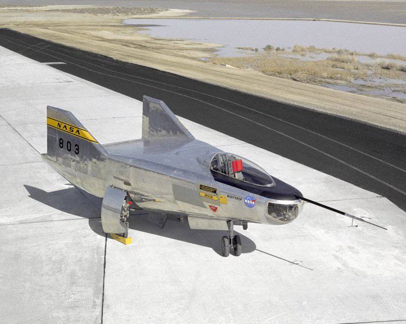
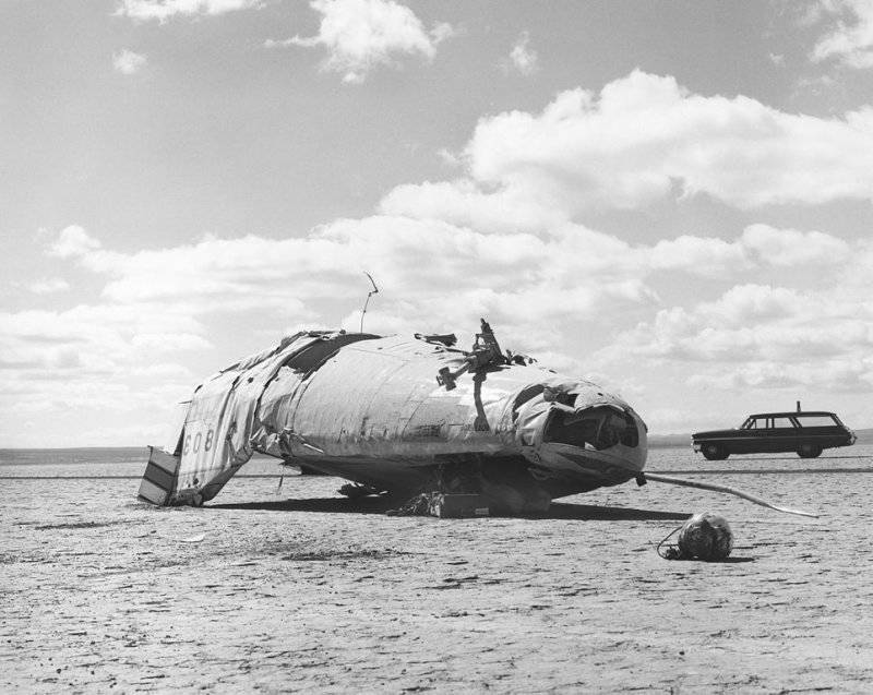
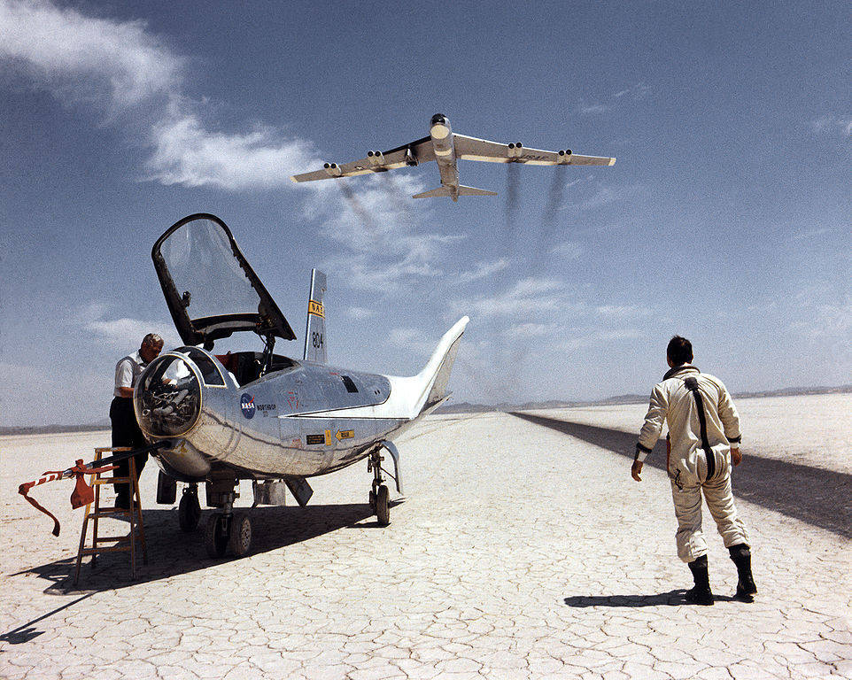
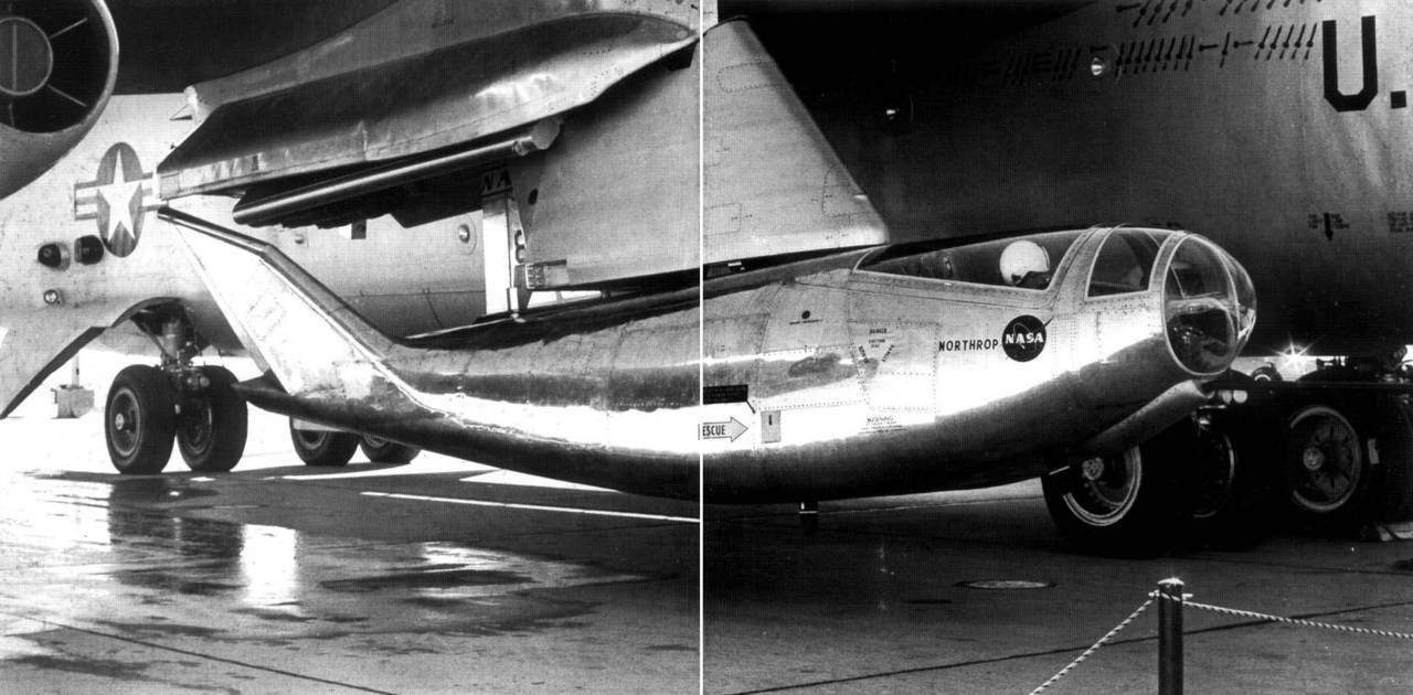
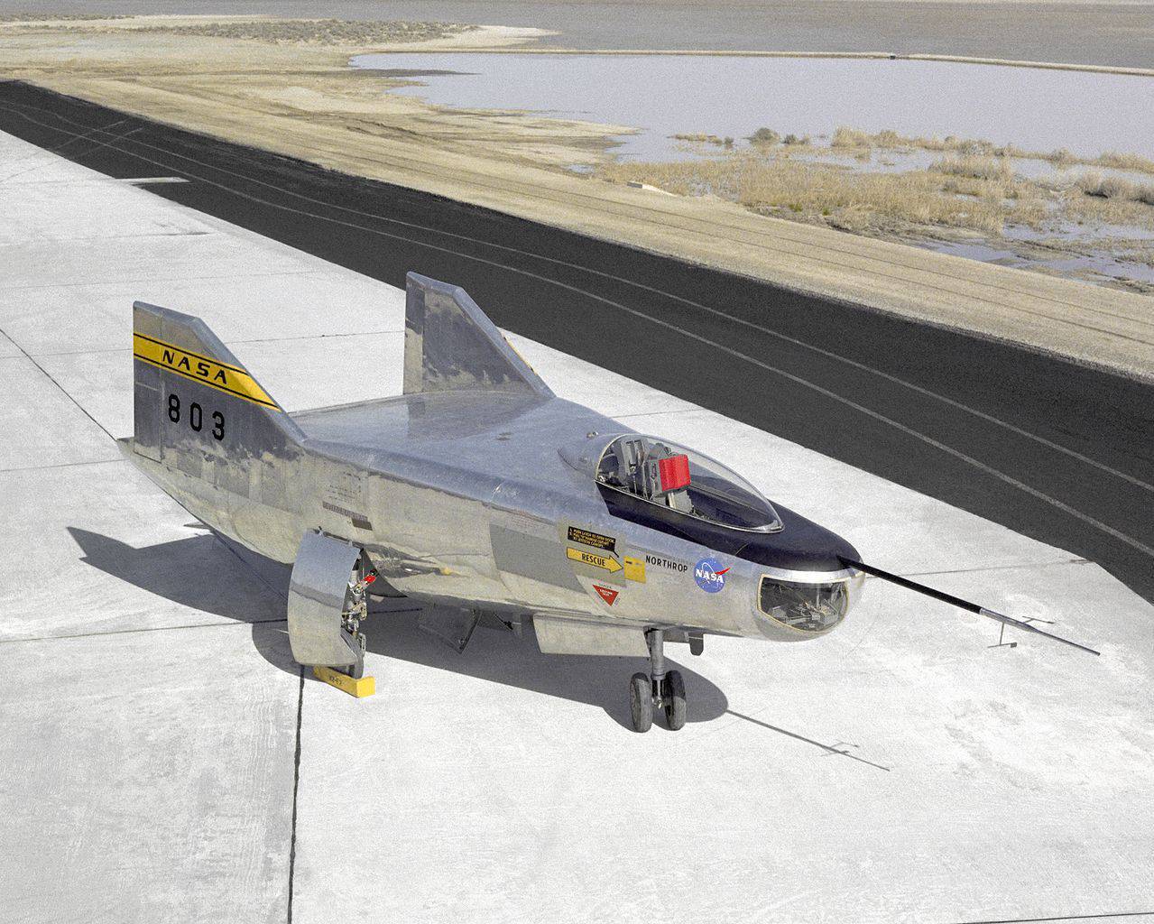
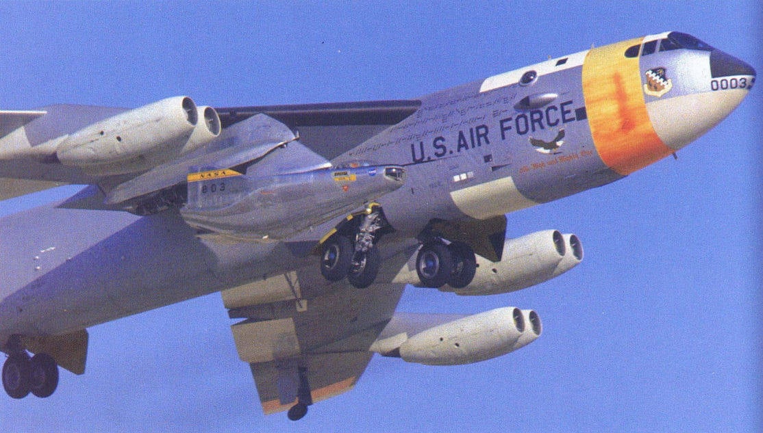
Flying fuselage Northrop M2-F2 and HL-10
Northrop HL-10 is one of the 5 aircraft of the NASA Edwards Flight Research Center (Dryda, California). These machines were built to study and test the possibilities of safe maneuvering and landing apparatus with low aerodynamic quality after returning from space. Studies using HL-10 and other similar devices were conducted in July 1966 - November 1975 of the year.
Based on theoretical studies at the beginning of 1950, the blunted nose cone was considered the most optimal form for the head of promising ballistic missiles. Upon entry into the atmosphere, a disconnected shock wave occurring in front of an apparatus with such a head significantly reduces thermal loads and allows an increase in the mass of the warhead by reducing the thickness of the thermal protective coatings.
NACA specialists who participated in these studies found that this relationship persists for half-cones. They also revealed another feature: during hypersonic flow, the difference in flow pressure to the lower and upper surfaces creates a lifting force, which significantly increases the maneuverability of the aircraft during de-orbiting.
Devices with a carrying case (this scheme was given such a name), according to their planning characteristics, occupy an intermediate position between ballistic capsules and orbital planes. In addition, the use of lowered capsules in the composition of manned spacecraft requires significant launch and return costs. The advantages of "bearing cases" include high structural excellence, reusable use, lower development cost compared to traditional video conferencing, etc.
Laboratory Specialists them. Ames, (hereinafter the Ames Center), was designed model of the device in the form of a blunted half-cone, having a flat upper surface. For road stability was supposed to use two vertical keels, which continue to fuselage contours. The returned spacecraft of this configuration was given the name M2.
Similar studies were conducted at the Langley Center. Employees have calculated several schemes for VKS with a carrying case. The most promising of these was the HL-10 project (“Horizontal Landing”; 10 is the sequence number of the proposed model). The HL-10 had an almost round in the middle of the middle surface with three keels, a flat, slightly arched bottom.
Given the high performance of NASA devices, in conjunction with the air force in 1961, they considered proposals for their use in the lunar program for the return of astronauts. However, the projects were not accepted. Despite the reduction in funding for pilot projects, this work continued through the efforts of enthusiasts. One model airplane manufactured a scale model of the device and conducted throwing tests. Real success allowed the test records to be demonstrated to the leadership of the Dryden and Ames Centers. The first allocated 10000 dollars from reserve funds for the manufacture of a full-scale apparatus and the second agreed to conduct aerodynamic tests. The device was given the designation M2-F1.
The six-meter model was made of aluminum tubes (power structure) and plywood (case). A pair of elevons was mounted on the upper edge of the tail section. External aluminum keels were equipped with rudders. Good purge results made it possible to proceed to taxi tests. But the lack of a suitable means for acceleration forced the purchase of a “Pontiac” with a forced engine, providing acceleration of the 450-kg model to 160 — 195 km / h. The controls had low efficiency and did not provide the required stabilization of the product. The problem was solved by abandoning the central keel and improving control surfaces.
In a number of runs, the model rose above the ground to a height of 6 m. The success of the tests allowed project participants to persuade the director of the Dryden Center to detach the vehicle for self-planning from the car. After that, the throwing tests of the model began, the vehicle was towed by a C-47 aircraft to 3 — 4 km altitudes. The first flight planner took place on August 16 1963. Overall, the M2-F1 has demonstrated good stability and control.
The spectacular flight of the device, as well as the low cost of the work performed, made it possible to expand the work on this subject.
In the middle of 1964, the US aerospace agency NASA signed a contract with Northrop for the construction of two wingless all-metal reusable devices with a main body. New devices assigned the designation HL-10 and M2-F2, differing in the profile of the supporting body.
In appearance, M2-F2 basically repeated M2-F1: a semi-cone with an upper flat surface was equipped with a pair of vertical keels without external elevons, the rudders could be used as brake plates. To expand the review, the cockpit was shifted forward, and the sock had glazing. To reduce the resistance and improve the flow conditions, the case of the model is somewhat lengthened. In the tail section of the M2-F2, there is a ventral pitch control flap, the upper surface of the hull was completed by a pair of elevator flaps, which provided roll control in antiphase.
Case Northrop HL-10 was an inverted half-cone with a rounded top of the fuselage and a flat bottom. In addition, there was a central keel. In the tail section, two trapezoidal elevons were installed with small plates. On the outer keels mounted balancing panels, and the central keel - split rudder. Balancing panels and flaps of the elevons were used for stabilization only during trans and supersonic flight. When planning after the active site at a speed of M = 0,6 — 0,8, they were fixed in order to avoid a sharp decrease in aerodynamic quality at the time of landing. The estimated landing speed should have been around 360 km / h.
Since rocket-winged aircraft were developed under fairly tight financial constraints, to save money, the vehicles were completed with ready-made units and elements: the main landing gear was taken from the F-5 fighter, the ejection seat — the F-106 fighter, and the T-39 fighter.
The instrumentation equipment of the aircraft was also distinguished by its simplicity - during the first flights they even had no spatial position sensors. The main measuring instruments are accelerometer, altimeter, speed sensors, slip and angle of attack.
Both vehicles were equipped with an XLR-11 engine (thrust 3,6 t), which was shortly used on an X-15 aircraft. To increase the range during an emergency landing, M2-F2 and HL-10 mounted auxiliary liquid-propellant rocket engines operating on hydrogen peroxide.
Fuel tanks models when performing throwing tests were filled with water mass 1,81 tons.
12 July 1966, the first planning flight M2-F2 took place. The model of 2,67 ton mass was separated from B-52 at a height of 13500 m at a speed of M = 0,6 (697 km / h). The duration of autonomous flight was 3 min 37 seconds. 10 May 1967, an emergency landing occurred. The reason for the loss of control was the “Dutch step”, during which the heel angle was 140 degrees.

They decided to restore the dilapidated apparatus by modifying the design. To provide lateral stability on the model, which received the designation M2-F3, installed the central keel and blocks of jet engines control system.
The throw test was resumed in June 1970. Six months later, the first flight took place with the inclusion of a cruising liquid rocket engine. At the final stage of testing, which ended in 1972, M2-F3 was used to solve various auxiliary tasks, including the development of a remote control system in the framework of the Space Shuttle program. The flight characteristics of the model were also assessed with extreme altitude-speed flight modes.
In December, the 1966 of the year began the throwing tests of the HL-10 apparatus. B-52 was also used for them. The first autonomous flight was complicated by serious problems - the control in the transverse direction was extremely unsatisfactory, the efficiency of the elevons during turnings dropped sharply. The deficiency was eliminated by a substantial refinement of the external carinae, which formed a stream above the control surfaces.
In the spring of 1968, Northrop HL-10 planning flights continued. The first launch of the sustained liquid-propellant rocket engine took place in October 1968.
The HL-10 was also used in the interests of the Space Shuttle. The last two flights of the vehicle, performed in the summer of 1970, were devoted to working off the landing with the power plant turned on. To this end, XLR-11 was replaced by three liquid rocket engines for hydrogen peroxide.
The experiment was generally considered successful - the engines that worked during landing reduced the glide path angle from 18 to 6 degrees. However, the pilot of the device noted that despite the work of ground-based guidance, there were some difficulties in determining the moment of inclusion of rocket engines.
Over the entire test period, HL-10 completed 37 starts. At the same time, the model set record flight height (27,5 km) and speed (M = 1,86) for rocket-planes with a carrying case.
Performance characteristics:
Length - 6,45 m;
Height - 2,92 m;
Wingspan - 4,15 m;
Wing area - 14,9 m²;
Empty weight - 2397 kg;
Full weight - 2721 kg;
Maximum take-off weight - 4540 kg (fuel - 1604 kg);
The power plant is a Reaction Motors XLR-11 four-chamber rocket engine (thrust to 35,7 kN);
Flight range - 72 km;
Practical ceiling - 27524 m;
Maximum speed - 1976 km / h;
Thrust coefficient per weight unit 1: 0,99;
Wing load - 304,7 kg / m²;
Crew - 1 man.
Based on materials:
http://www.walkinspace.ru
http://crimso.msk.ru
http://zona58.ru
Based on theoretical studies at the beginning of 1950, the blunted nose cone was considered the most optimal form for the head of promising ballistic missiles. Upon entry into the atmosphere, a disconnected shock wave occurring in front of an apparatus with such a head significantly reduces thermal loads and allows an increase in the mass of the warhead by reducing the thickness of the thermal protective coatings.
NACA specialists who participated in these studies found that this relationship persists for half-cones. They also revealed another feature: during hypersonic flow, the difference in flow pressure to the lower and upper surfaces creates a lifting force, which significantly increases the maneuverability of the aircraft during de-orbiting.
Devices with a carrying case (this scheme was given such a name), according to their planning characteristics, occupy an intermediate position between ballistic capsules and orbital planes. In addition, the use of lowered capsules in the composition of manned spacecraft requires significant launch and return costs. The advantages of "bearing cases" include high structural excellence, reusable use, lower development cost compared to traditional video conferencing, etc.
Laboratory Specialists them. Ames, (hereinafter the Ames Center), was designed model of the device in the form of a blunted half-cone, having a flat upper surface. For road stability was supposed to use two vertical keels, which continue to fuselage contours. The returned spacecraft of this configuration was given the name M2.
Similar studies were conducted at the Langley Center. Employees have calculated several schemes for VKS with a carrying case. The most promising of these was the HL-10 project (“Horizontal Landing”; 10 is the sequence number of the proposed model). The HL-10 had an almost round in the middle of the middle surface with three keels, a flat, slightly arched bottom.
Given the high performance of NASA devices, in conjunction with the air force in 1961, they considered proposals for their use in the lunar program for the return of astronauts. However, the projects were not accepted. Despite the reduction in funding for pilot projects, this work continued through the efforts of enthusiasts. One model airplane manufactured a scale model of the device and conducted throwing tests. Real success allowed the test records to be demonstrated to the leadership of the Dryden and Ames Centers. The first allocated 10000 dollars from reserve funds for the manufacture of a full-scale apparatus and the second agreed to conduct aerodynamic tests. The device was given the designation M2-F1.
The six-meter model was made of aluminum tubes (power structure) and plywood (case). A pair of elevons was mounted on the upper edge of the tail section. External aluminum keels were equipped with rudders. Good purge results made it possible to proceed to taxi tests. But the lack of a suitable means for acceleration forced the purchase of a “Pontiac” with a forced engine, providing acceleration of the 450-kg model to 160 — 195 km / h. The controls had low efficiency and did not provide the required stabilization of the product. The problem was solved by abandoning the central keel and improving control surfaces.
In a number of runs, the model rose above the ground to a height of 6 m. The success of the tests allowed project participants to persuade the director of the Dryden Center to detach the vehicle for self-planning from the car. After that, the throwing tests of the model began, the vehicle was towed by a C-47 aircraft to 3 — 4 km altitudes. The first flight planner took place on August 16 1963. Overall, the M2-F1 has demonstrated good stability and control.
The spectacular flight of the device, as well as the low cost of the work performed, made it possible to expand the work on this subject.
In the middle of 1964, the US aerospace agency NASA signed a contract with Northrop for the construction of two wingless all-metal reusable devices with a main body. New devices assigned the designation HL-10 and M2-F2, differing in the profile of the supporting body.

In appearance, M2-F2 basically repeated M2-F1: a semi-cone with an upper flat surface was equipped with a pair of vertical keels without external elevons, the rudders could be used as brake plates. To expand the review, the cockpit was shifted forward, and the sock had glazing. To reduce the resistance and improve the flow conditions, the case of the model is somewhat lengthened. In the tail section of the M2-F2, there is a ventral pitch control flap, the upper surface of the hull was completed by a pair of elevator flaps, which provided roll control in antiphase.
Case Northrop HL-10 was an inverted half-cone with a rounded top of the fuselage and a flat bottom. In addition, there was a central keel. In the tail section, two trapezoidal elevons were installed with small plates. On the outer keels mounted balancing panels, and the central keel - split rudder. Balancing panels and flaps of the elevons were used for stabilization only during trans and supersonic flight. When planning after the active site at a speed of M = 0,6 — 0,8, they were fixed in order to avoid a sharp decrease in aerodynamic quality at the time of landing. The estimated landing speed should have been around 360 km / h.
Since rocket-winged aircraft were developed under fairly tight financial constraints, to save money, the vehicles were completed with ready-made units and elements: the main landing gear was taken from the F-5 fighter, the ejection seat — the F-106 fighter, and the T-39 fighter.
The instrumentation equipment of the aircraft was also distinguished by its simplicity - during the first flights they even had no spatial position sensors. The main measuring instruments are accelerometer, altimeter, speed sensors, slip and angle of attack.
Both vehicles were equipped with an XLR-11 engine (thrust 3,6 t), which was shortly used on an X-15 aircraft. To increase the range during an emergency landing, M2-F2 and HL-10 mounted auxiliary liquid-propellant rocket engines operating on hydrogen peroxide.
Fuel tanks models when performing throwing tests were filled with water mass 1,81 tons.
12 July 1966, the first planning flight M2-F2 took place. The model of 2,67 ton mass was separated from B-52 at a height of 13500 m at a speed of M = 0,6 (697 km / h). The duration of autonomous flight was 3 min 37 seconds. 10 May 1967, an emergency landing occurred. The reason for the loss of control was the “Dutch step”, during which the heel angle was 140 degrees.
They decided to restore the dilapidated apparatus by modifying the design. To provide lateral stability on the model, which received the designation M2-F3, installed the central keel and blocks of jet engines control system.
The throw test was resumed in June 1970. Six months later, the first flight took place with the inclusion of a cruising liquid rocket engine. At the final stage of testing, which ended in 1972, M2-F3 was used to solve various auxiliary tasks, including the development of a remote control system in the framework of the Space Shuttle program. The flight characteristics of the model were also assessed with extreme altitude-speed flight modes.
In December, the 1966 of the year began the throwing tests of the HL-10 apparatus. B-52 was also used for them. The first autonomous flight was complicated by serious problems - the control in the transverse direction was extremely unsatisfactory, the efficiency of the elevons during turnings dropped sharply. The deficiency was eliminated by a substantial refinement of the external carinae, which formed a stream above the control surfaces.
In the spring of 1968, Northrop HL-10 planning flights continued. The first launch of the sustained liquid-propellant rocket engine took place in October 1968.
The HL-10 was also used in the interests of the Space Shuttle. The last two flights of the vehicle, performed in the summer of 1970, were devoted to working off the landing with the power plant turned on. To this end, XLR-11 was replaced by three liquid rocket engines for hydrogen peroxide.
The experiment was generally considered successful - the engines that worked during landing reduced the glide path angle from 18 to 6 degrees. However, the pilot of the device noted that despite the work of ground-based guidance, there were some difficulties in determining the moment of inclusion of rocket engines.
Over the entire test period, HL-10 completed 37 starts. At the same time, the model set record flight height (27,5 km) and speed (M = 1,86) for rocket-planes with a carrying case.
Performance characteristics:
Length - 6,45 m;
Height - 2,92 m;
Wingspan - 4,15 m;
Wing area - 14,9 m²;
Empty weight - 2397 kg;
Full weight - 2721 kg;
Maximum take-off weight - 4540 kg (fuel - 1604 kg);
The power plant is a Reaction Motors XLR-11 four-chamber rocket engine (thrust to 35,7 kN);
Flight range - 72 km;
Practical ceiling - 27524 m;
Maximum speed - 1976 km / h;
Thrust coefficient per weight unit 1: 0,99;
Wing load - 304,7 kg / m²;
Crew - 1 man.
Based on materials:
http://www.walkinspace.ru
http://crimso.msk.ru
http://zona58.ru
Information