How to Catch a Drone by Ear: A Five-Unknown Problem
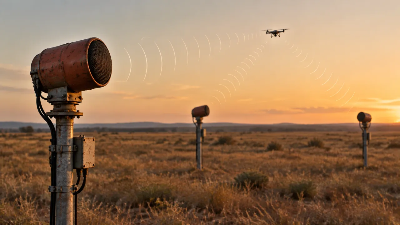
This is my continuation of the topic of sound location of air targets. In my previous article (Some challenges of drone acoustic location: why sound is not radio) I rashly promised to further analyze the possibilities of using the correlation-difference-rangefinding method of location. However, I soon became convinced that for a running engine drone This method will not work due to the regular structure of the sound.
Instead, I present to you another article analyzing passive sound location. The task appears to be non-trivial. I've outlined a solution.
Introduction
Drones-Drones have become widespread over the past decade weapons, which is revolutionizing military affairs before our very eyes. They are distinguished by their small size, low speed, and the ability to fly at extremely low altitudes while following terrain. This significantly complicates their detection by radar. Clearly, something needs to be developed to counter drones. In particular, it makes sense to try to detect and track them by the sound of their engines.
Sound ranging of air targets is the detection of flying aerial objects and the estimation of their coordinates and movement parameters based on the sound they emit. This is not a new concept; it will soon be 100 years old.
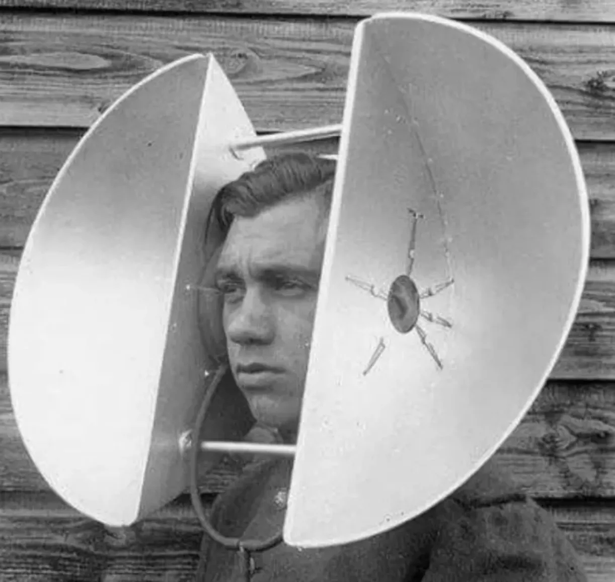
However, the author was unable to find a systematic analysis of the technical capabilities of sound ranging, particularly as it applies to drones, which have found widespread military use in the last decade. This article should, to some extent, fill this gap.
The sound of a drone's engine isn't particularly loud compared to an aircraft engine. Even a highly sensitive microphone can detect it at a range of no more than a few kilometers. We won't consider even more sensitive directional microphones here, as their use would require scanning the airspace using angular coordinates, significantly complicating the system. Therefore, we'll leave the angular (direction-finding) method of determining coordinates aside.
In passive radar, a correlation-based difference-ranging method for determining the coordinates of a noise jammer is well known. It is based on measuring the differences in signal propagation times to several receiving points located across the terrain. This difference is measured for each pair of receiving points using a cross-correlation function. Due to the purely random nature of the received jamming signals, this function has a single peak at the time delay corresponding to the difference in signal propagation times. This allows it to be measured. However, in the case of sound ranging, the signal has a significantly more regular, almost periodic, structure due to the operation of the air target's engine. Therefore, the cross-correlation function will have multiple peaks with a step size corresponding to the engine operating period. For example, at a frequency of thousands of revolutions per minute, the peaks of the sound correlation function will be spaced at intervals of tens of milliseconds, which corresponds to a spatial unambiguous interval of only a few meters, whereas we need thousands of meters. This precludes the use of the correlation-based difference-ranging method in the sound location of air targets.
In this article, we examine sound location using a single signal parameter—its frequency, observed over time from a single location or instantaneous frequency measurements taken simultaneously at multiple locations. Our method utilizes the Doppler effect, which causes the observed frequency to vary across different measurements. Based on these differences, we calculate the coordinates and velocity vector of an airborne target.
In considering the subject, we make a number of simplifying assumptions and accept several restrictions, namely:
- An aerial target (drone) on the observed section of the trajectory moves in a straight line at a constant speed.
- The sound of an aerial object propagates equally in all directions, having the same frequency spectrum.
- The detection system consists of a group of points dispersed in open areas, eliminating the possibility of reflected sounds. Interfering background sounds are virtually eliminated.
- Each receiving station has an omnidirectional microphone, a primary processing device for incoming audio signals, and data transmission facilities for the information consumers. The receiving station processes only audio by analyzing its frequency spectrum.
- A spectrum is characterized by a so-called characteristic frequency. This can be the frequency of the strongest harmonic (mode) or the spectrum width (average frequency or median). Therefore, a flying object can be considered to emit a monochromatic sound, the frequency of which may vary at different points due to the Doppler effect. During initial processing, the receiving station evaluates this frequency and, based on this frequency alone, can assess the remaining parameters of the aerial target.
- We consider the cases of a single receiving station and a system of cooperative stations that hear the sound of only a single air target.
- The stations are arranged so that several stations can simultaneously receive the sound of an airborne object. They can transmit the results of their primary processing to a central station for joint secondary processing with negligible latency.
- Simultaneous engagement of multiple aerial targets and measurement of bearings and/or other individual target characteristics requires separate consideration and is beyond the scope of our analysis.
It's well known that the detection range of an acoustic signal is limited to a few kilometers. Therefore, if high accuracy is required, acoustic location in the immediate vicinity of receiving points may be considered. From a tactical perspective, the Troops Defense This means that the sound location system can only serve short-range firepower as a target designation tool. It is desirable for the accuracy of determining the coordinates and velocity vector of a flying drone to be sufficient to allow targeting without additional search. Such a target could be an anti-aircraft machine gun or laser cannon located near the defended facility.
A sound ranging system can be effective as an early detection tool if the receiving station strip is sufficiently long and can be located at a significant distance from the defended facilities. Several such strips can be established at different points, complementing radar systems. The low cost of acoustic locators makes this possible.
Capabilities of a single reception center
For analysis, let's consider the circuit diagram Fig. 1This is a two-dimensional case. The coordinate system is chosen so that the target trajectory is parallel to the axis yThe velocity vector is directed toward decreasing this coordinate. The receiving point is located at the origin. In the following discussion, we will use capital letters to denote the sought-for quantities, and lowercase letters to denote known parameters.
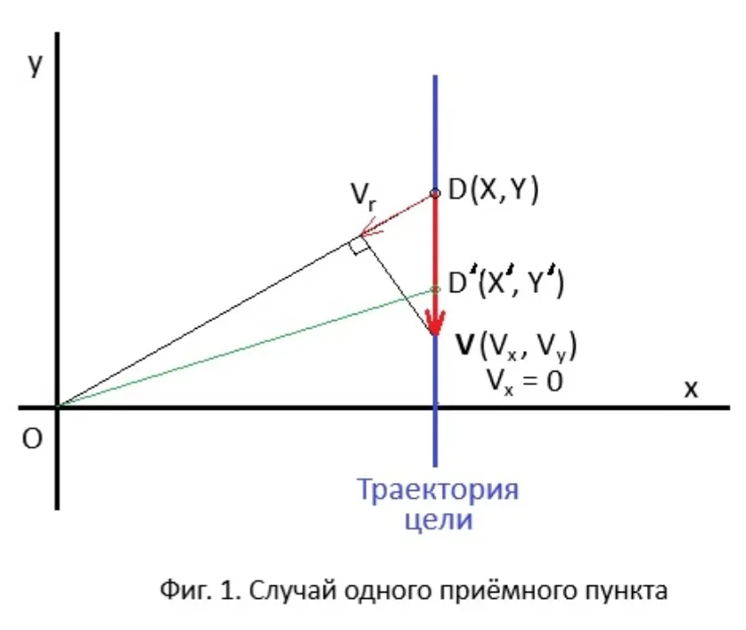
At the moment of receiving the sound signal the target was at the point D with coordinates (X, Y) and had a velocity vector V(Vx, Vy). At the moment when the sound reaches the receiving point, the target will fly some distance and end up at the point D'(X', Y'). Thus, the coordinates (X, Y) are apparent, and (X', Y') - real. Target speed V(Vx, Vy) along the entire trajectory, including at the actual point D' We consider it unchanged.
In the case of passive radar, the difference between the points D и D' Usually so small that it is neglected. In sound location, due to the relatively low speed of sound propagation, a correction is necessary. In the case of multi-location, these corrections differ for different receiving points. This is one of the peculiarities of sound location.
We want to estimate the parameters (X', Y', Vx, Vy) by the received sound with the observed frequency
f = F' + dF,
where F' - a characteristic frequency of sound unknown to us and dF - positive or negative correction, or Doppler frequency, which we also need to determine.
The latter can be calculated using the formula:
dF = 2 *Vr*F' / c,
where Vr - radial velocity of the target relative to the receiving point,
c - the speed of sound (about 340 m/s).
For example, for an air target flying straight towards the receiving point and with a characteristic sound frequency of 170 Hz and a speed of 50 m/s (like an airplane) An-2), we get:
dF = 2 * 50 * 170 / 340 = 50 Hz.
That is, the frequency of the perceived sound will be 220 Hz.
Since the characteristic frequency F' will be required for intermediate calculations, we will be forced to evaluate it too.
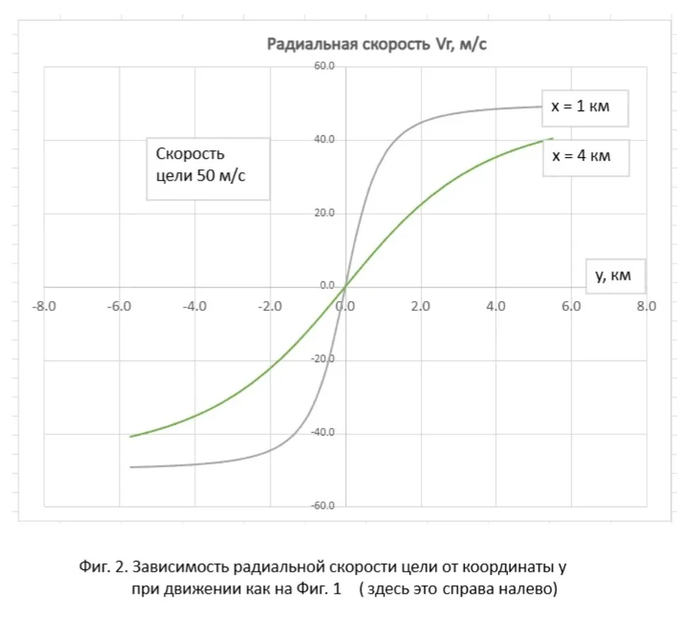
For Fig. 2 The graphs of the dependence of the radial velocity (and the Doppler frequency proportional to it) on the position of an air target are shown, assuming that it flies as shown in Fig. 1. That is, the coordinate y decreases, and looking at Fig. 2, we can assume that the target is moving from right to left. The Doppler frequency decreases monotonically. The steepness of the curve abeam the receiving station depends on the target's course parameter. x, i.e., its minimum distance from the receiving point. Two graphs are shown for the parameter 1 km and 4 km.
Doppler frequency unknown to us dF proportional to the radial velocity of the target Vr relative to the receiving point. It is "hidden" within the observed frequency f received audio signal. Frequency f carries information about all the parameters of the air target that interest us.
g(f) = (X', Y', Vx, Vy, F'),
Where g(.) is a function that connects these variables.
Thus, by measuring just one parameter f, in the two-dimensional case we want to estimate five unknowns. (In the three-dimensional case there will be seven unknowns, since Z и Vz).
To solve this problem, we have to measure the frequency f at least at five points along the trajectory, relying on the fact that due to the Doppler effect in changing f The parameters of the aerial target will become apparent. The curve in Fig. 2 shows that the Doppler frequency changes are more pronounced when the aerial target passes near the course parameter. This indicates that in the presence of frequency measurement errors at large distances, the Doppler effect may be excessively distorted by these errors. The best accuracy should be expected when the target passes overhead.
Calculation formulas and equations[/h3]
Here we are talking about expressions that connect the values of the sought variables with the observed sound frequency.
Let i-th receiving point is located not at the origin, but at the point Oi, coordinates xi, yi which are known (i = 0, 1, ... , n-1). Our formulas work for both single-position and multi-position cases. The only difference is that in the second case, measurements are taken simultaneously, while in the first case, they are taken at different points in time. Oi does not depend on the index i, which is equal to zero.
The target course is arbitrary with a constant velocity vector V (Vx, Vy). In the single-position case, the true coordinates of the target change according to a linear law:
X'i = X0 + Vx* i * tau, (1)
Y'i = Y0 + Vy* i * tau, (2)
where tau is the time interval between measurements.
Since in the multi-position case the air target is observed by all points simultaneously, the true coordinates of the target do not depend on the index iAll other mathematical expressions are the same for both cases.
Let the apparent position of the target be a point Di (Xi, Yi); in general, it is different for each measurement, both for single-position and multi-position location. The distance to this point is determined by the formula:

The apparent coordinates included in it Xi, Yi We have yet to determine.
Using the diagram in Fig. 1, we note that the radial velocity is the projection of the velocity vector onto the radius vector of the target. OiDiUsing the scalar product of vectors, one can obtain an expression for the radial velocity Fri. with i-m dimension:

Denominator is the length of the target radius vector OiDi, the numerator is the scalar product of this vector and the velocity vector V (Vx, Vy). The latter is the same for all measurements. We find it using the measured frequency. fi:
fi = F' + dFi, (5)
where F' - characteristic frequency of sound and dFi - Doppler frequency at i-m dimension.
The latter can be calculated using the formula:
dFi = 2 * Vri * F' / c, (6)
Where c - the speed of sound.
Knowing the speed of sound propagation, we will find the delay time
dti = di / c. (7)
This will allow you to extrapolate the apparent position of the target to the true one and find the actual coordinates of the target:
D'(X', Y') = Di (Xi, Yi) and V (Vx, Vy) * dt. (8)
The last expression is vectorial and contains two scalar equations.
An attentive reader may have noticed that the given equations contain apparent coordinates Xi, Yi. Knowing di, dti, they are determined by solving a system of equations.
Thus, for each of n sound frequency measurements f0, f1, ... , fn-1 we have a set of formulas (1)-(8) that give us the function gi(fi) = (X', Y', Vx, Vy, di, dti, F') for i-th dimension. All these n sets form a system of equations that must be solved for unknown variables (X', Y', Vx, Vy, di, dti, F').
Since in the single-position case the measurements are made at known, but different, points in time, each of the variables X' и Y' will be presented by a set n values corresponding to these moments in time. In this case, we evaluate the coordinate values only for the last moment in time. Therefore, the system of equations will include the equations of motion of the observed aerial target (1), (2). In the multi-position case, these formulas will not exist.
Equations (3) and (4), however, are nonlinear, and the system of equations is unlikely to be solved analytically. This forces us to use numerical methods. This will require more the skill of applied mathematics than mathematical theory itself. The author leaves the demonstration of this skill to the reader.
Features of a multi-position system compared to a single-position system
A single-position passive sound ranging system is advantageous due to its extreme simplicity. The receiving station only needs to contain a sensitive omnidirectional microphone and simple electronic devices for amplifying the received signal, analyzing its spectrum, calculating target coordinates based on observations over a period of time (from a few to tens of seconds), and transmitting the coordinate and velocity estimates to the user.
A drawback of a single-position system is the assumption of a uniform, rectilinear target motion. If the target maneuvers, the accuracy of the calculations can be significantly reduced. If another similar aerial target flying at a similar speed appears in the detection zone during the observation period, this could confuse the calculations.
By complicating the location system, we can partially or completely eliminate the shortcomings of a single-position system. We trade off reduced time for increased spatial dimensions.
In the case of a multi-position system, the same mathematical formulas apply. The only difference is that for each sound frequency measurement, the coordinates of the receiving point xi, yi will have their own (i = 0, 1, ... , n-1). Also, when performing calculations, it should be kept in mind that when simultaneously receiving a sound signal at each point, the apparent positions of the target will correspond to different moments in time (Fig. 3). When calculating the true coordinates, this is taken into account by formula (8). With correct calculations, the extrapolated apparent positions of the target should coincide at the true point D'(X', Y').
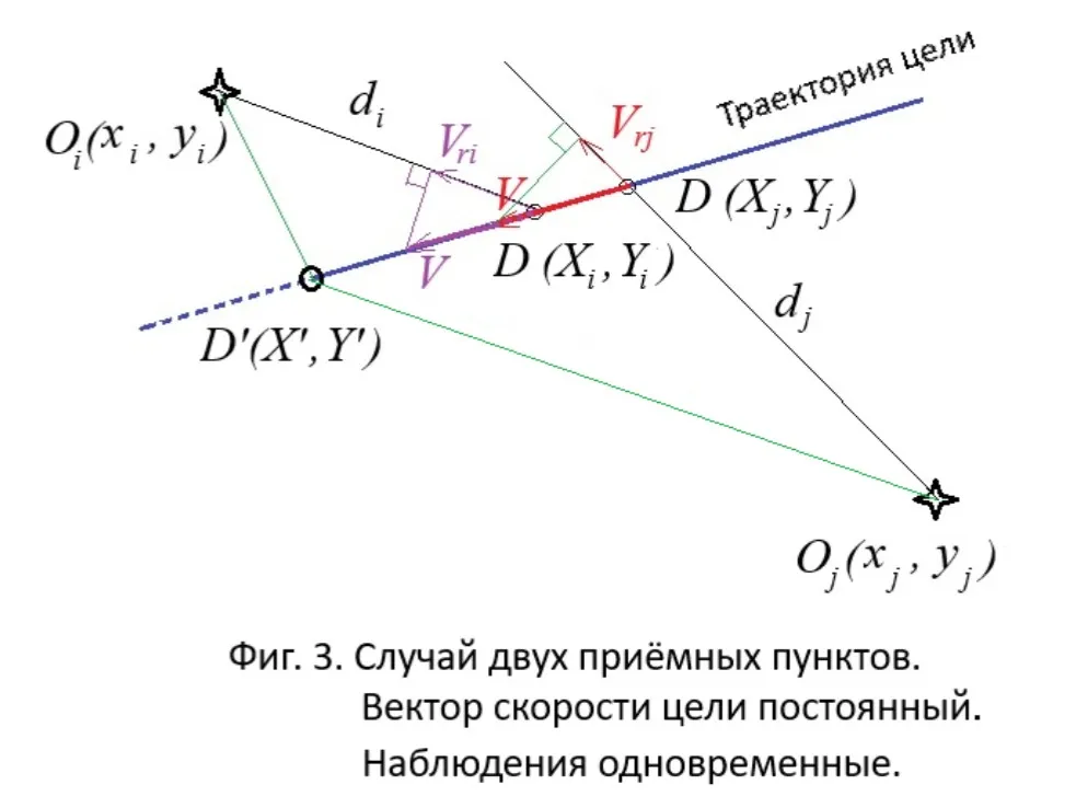
The single-position case differs only in that for each observation, the extrapolation of the apparent coordinates to the true point corresponding to the moment of the latter, (n-1)-th, observations are carried out according to a formula that takes into account the non-simultaneity of observations.
The obvious advantage of the multi-position method is that the full set of air target characteristics is determined almost instantly. "Almost" because during initial processing, some time is required to measure the spectrum of the sound signal and determine its characteristic frequency. That is, it's not exactly instantaneous. The lower the frequency of the sound, the longer it takes to evaluate its spectrum. In practice, this is the duration of 20-50 oscillation periods of the lowest tone. Therefore, for a frequency of 50 Hz, we spend up to one second determining the characteristic frequency. This delay must be taken into account when calculating the delay time included in formula (8).
Another advantage is that our assumption of uniform, rectilinear target motion is somewhat relaxed. The target only needs to maintain a constant velocity vector during the time it takes for the sound spectrum to be measured by all receiving stations. This means that it is possible to work against moderately maneuvering targets.
A disadvantage of a multi-position system is that we would need several receiving stations that could simultaneously and reliably detect the sound generated by an aerial target. Furthermore, the configuration of a minimal number of receiving stations is limited by the existence of blind spots. These are the positions of an aerial target when it is close to a straight line connecting a pair of receiving stations and is located on the same side of them. Since the Doppler frequency will be the same at these stations, our system of equations will not have a unique solution.
An interesting generalization could be the case where some receiving stations operate in single-position mode, while others operate in a distributed system, and their measurement results are combined. This can be useful when an aerial target is not observed by all stations simultaneously.
A possible approach to solving the acoustic location problem[/h3]
Let's clarify right away that the author does not yet have a ready-made method for solving the system of equations for passive sound location. This section presents only the basic ideas.
Equations (1)-(8) allow, given the configuration of receiving points and the parameters of the air target trajectory and the true frequency of its sound, to calculate the expected values of the frequency of the received sound signal at each receiving point.
Below is an example for six receiver stations, evenly spaced around a circle with a radius of 2000 meters. The target coordinates, velocity vectors, and characteristic sound frequency at the time of measurement are shown above the table. Each row corresponds to one receiver station. The table lists the coordinates of the receiver stations, the distances to the apparent target positions, the target's radial velocities relative to these stations, the Doppler frequencies, and the observed sound frequencies.
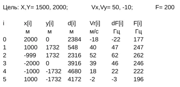
Such calculations are straightforward and can be used to generate data for testing a program for solving a sound-based location problem. That is, solving a problem that is the inverse of generating data like those shown in the table. However, developing such an algorithm is a non-trivial task. A possible approach to its solution is outlined below.
The solution can be found using the brute force method by trying various acceptable combinations of the desired parameters. X', Y', Vx, Vy, di, dti, F' and as a solution, select the combination that best satisfies the constraints imposed by formulas (1)-(8). Note that in the presence of n reception points of unknown independent variables will be 2*n + 5That is, for example, when n = 5 The solution must be searched for in a 15-dimensional space. The criterion could be the standard deviation of the observed sound frequencies from the frequencies calculated using formulas (1)–(8). However, such a simple solution search method would require an excessive number of trial calculations.
The range of acceptable values of unknown parameters can be significantly reduced by using two groups of additional constraints arising from the specific features of the problem under consideration.
First group: all n the apparent coordinates of the target and its actual position must lie on the same line. This gives rise to 2*n linear equations.
The second group: the target velocity vectors, constructed from the radial velocity vectors relative to each pair of receiving points, must be equal. For example, in Fig. 3, the pair of vectors Vri и Vrj allow you to calculate the target's velocity vector Vij. (The subscripts indicate the numbers of the reception points.) There are such pairs N = n*(n-1)/2. This gives rise to more N*(N - 1)/2 linear equations. When n = 5 we have 10 pairs and 45 equations.
This set of constraints significantly speeds up the search, making it easy to filter out unsuitable trial sets of values for unknown variables and even conduct a directed search for a solution.
This class of problems in applied mathematics is called constraint satisfaction problems. This area has already been studied in considerable depth, and there are even software packages for languages Python и Java to solve them. The reader must learn to use these packages and represent the constraints in the required form.
However, it's worth cautioning against hasty steps. In our case, frequency measurements will be inaccurate due to interference. Therefore, some equations will not be satisfied simultaneously, and the solution to the problem will not converge completely. For example, not all velocity vectors will be absolutely identical, and the calculated frequency values will not all be exactly equal to the measured ones. Thus, we arrive at the problem of satisfying fuzzy constraints. The interested reader is encouraged to explore the methods for solving this class of problems.
Conclusion
We've only examined the basic mathematical relationships between the measured frequency of a sound signal and the coordinates and motion parameters of the sound source. Two sets of questions remain unresolved for developing practical recommendations: technical and tactical.
Technical issues include the choice of a method for solving the system of equations, as well as ways to further refine the proposed mathematical model. Specifically, instead of a discrete method in the single-position case, the use of continuous-time equations and nonlinear filtering techniques suggests itself. It is also necessary to analyze the influence of a number of factors on the accuracy of estimating coordinates and the velocity vector, and develop appropriate recommendations. Since the entire game is played in terms of the Doppler frequency, it should be noted that accuracy will depend on the curvature of the curve in Fig. 2. The greater the curvature, the higher the accuracy. This influences the choice of timing for measurements. The selection of the characteristic frequency of the received sound also remains an open question. It would be desirable for the accuracy of the acoustic passive locator to allow target designation to short-range air defense weapons, which could immediately open fire without searching for a target.
Complex technical issues that remain to be explored include multipath propagation of sound waves, simultaneous engagement of multiple airborne targets, and the combined use of acoustic and other location methods. This places limitations on the tactical capabilities of the location method we've described.
Tactical issues relate to the study of options for constructing an acoustic location system at the lower level of the air defense system and methods for its combat use. Their solution depends on the resolution of technical issues, including the choice of configuration for a multi-position grouping of receiving stations. If an air target is too far away compared to the radius of the grouping, the sound frequencies received by different stations will have similar values, and the difference between them may be lost in measurement noise. Therefore, with an excessively dense grouping, solving the system of equations can lead to excessively large errors.
A cunning adversary could send us a very slow-flying balloon carrying a fairly powerful sound source. Due to the source's low speed, the observed frequency of this sound will be virtually identical at all receiving points. Under these conditions, the location methods described above will be ineffective. An adversary could also intentionally modulate the drone's engine speed to make frequency-based location difficult. These issues require separate consideration.
Thus, many interesting questions remain for further research.
Information