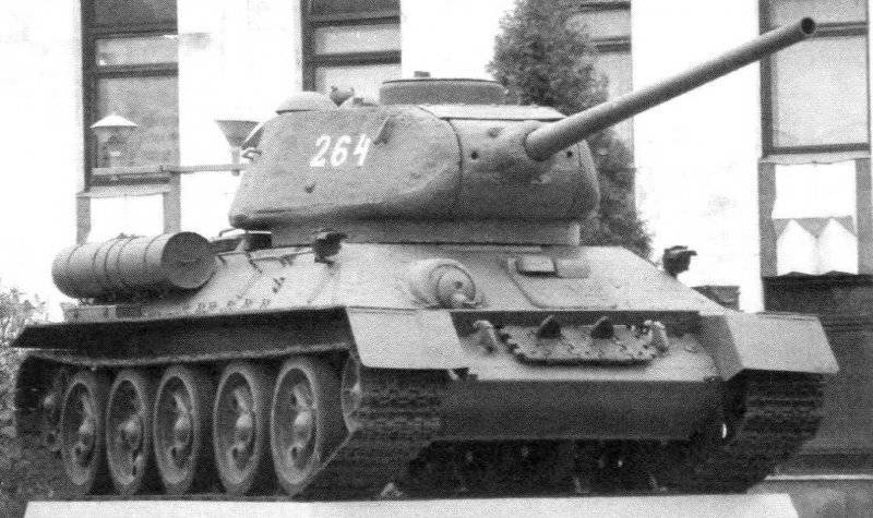
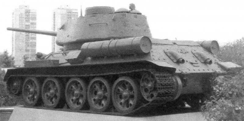
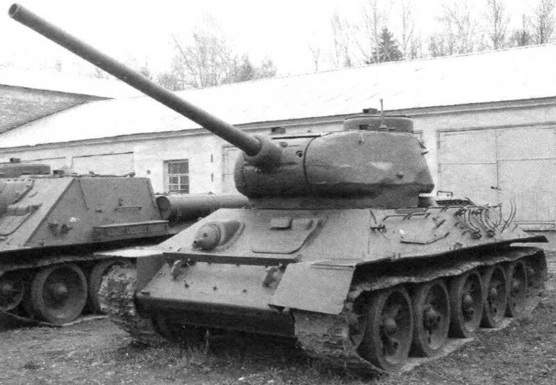
Modernized medium tanks in the postwar period. Tank T-34-85 arr. 1960
Tank T-34-85 arr. 1960 G. was an improved T-34-85 arr. 1944 of the period of the Great Patriotic War, developed in the design bureau of the plant №112 "Krasnoye Sormovo" in Gorky (now Nizhny Novgorod) under the leadership of the chief designer of the plant V.V. Krylova in January 1944. The technical documentation for the car was subsequently approved by the main plant No. XXUMX in Nizhny Tagil (chief designer - A. A. Morozov). The tank was put into service by the Red Army by the resolution of the State Defense Committee No. 183 of 5020 in January 23 and was produced at the plants No. 1944, No. 183 Red Sormovo and No. 112 in Omsk from March 174 to December 1944. In the post-war period, the plants of industry released 1946 tank5742.
In 1947, the machine was assigned the factory designation "Object 135", and in the 1950s. it was repeatedly subjected to modernization, which was carried out at capital repair plants of the USSR Ministry of Defense. Modernization measures (aimed at improving the performance of combat and technical characteristics, improving the reliability of components and assemblies tank, convenience of its maintenance) on the instructions of GBTU developed CEZ No. 1 and VNII-100. The final development of the drawing-technical documentation for modernization, which was approved in 1960, was carried out by the design bureau of the plant No. 183 in Nizhny Tagil under the supervision of the chief designer L.N. Kartseva.
Tank T-34-85 arr. 1960 had a classic general layout with a crew of five and placement of internal equipment in four divisions: control, combat, engine, and transmission. Armored hull, turret, armament, power plant, transmission and undercarriage compared with the T-34-85 tank arr. 1944 did not undergo significant changes.
The department of management housed the workplaces of the driver (left) and the machine-gunner (right), the tank's controls, the DTM machine gun in a spherical installation, instrumentation, two compressed air cylinders, two hand-held fire extinguishers, a TPU apparatus, and part of the ammunition kit and spare parts. Landing and exit of the driver was made through the hatch, located in the upper front hull sheet and closed armor cover. In the lid of the driver's hatch there were two viewing instruments installed to increase the horizontal viewing angle at an angle to the longitudinal axis of the hatch with a turn towards the sides of the hull.


When driving at night, the BVN night vision device was installed by the driver with the 1959 to monitor the road and terrain. In addition to the device itself, its kit included a high-voltage power supply unit, FG-100 headlight with an infrared filter and spare parts. In the off position, the BVN device and the instrument spare parts kit were stored in the packing box, which was located on the first box of the combat pack behind the driver’s seat. An additional optical element with an infrared filter was mounted on a bracket in the forward part of the body. When used, the BVN device was mounted in a removable bracket mounted on the beams welded to the upper front plate on the right side of the driver's hatch (the driver's hatch cover was in the open position). The power supply of the device was placed on the bracket, on the left side of the tank, the headlight FG-100 with an infrared filter - on the right side of the hull. An optical element with a blackout nozzle was removed from the left headlight of FG-102, and an optical element with an infrared filter was used instead.
In the bottom of the control compartment, in front of the machine gunner’s seat, there was a spare hatch that was closed with an armor cover, which was folded down (on one loop).
In the fighting compartment, which occupied the middle part of the tank hull and the internal volume of the turret, were placed tank armament with aiming devices and aiming mechanisms, surveillance devices, some ammunition, communication equipment and jobs, to the left of the gunner and tank commander. Above the commander's seat, on the roof of the tower, was a non-rotating commander's turret, in the side walls of which there were five viewing slots with protective glass, providing him with a circular view, and an access hatch closed by an armor cover. In the rotary base of the commander's hatch to 1960, the periscope viewing device MK-4 was installed, instead of which the viewing device TPK-1 or TPKU-2B165 was then used. Above the workplaces of the loader and the gunner in the roof of the tower was installed on one rotary periscopic device MK-4. In addition to the access hatch in the commander’s turret, a hatch in the right side of the tower’s roof above the loading station was used to land the crew located in the turret. The hatch was closed with a folding (on one loop) armored cap.
With 1955 in the fighting compartment at the left side of the tank mounted boiler nozzle heater, included in the engine cooling system.
The engine compartment was located behind the military and was separated from it by a removable partition. It housed the engine, two radiators and four batteries. When installing the heater in the upper removable and left non-removable sheets of the partition, a cutout was made for access to the heater supercharger, which was covered with a casing, and there was a window in the door of the side sheet for heater heater connections.
The transmission compartment was located in the rear part of the hull and was separated from the engine compartment by a partition. It installed the main clutch with a centrifugal fan and other transmission units, as well as electric starter, fuel tanks and air purifiers. The main weapon of the tank was the 85-mm tank gun ZIS-S-53 with a vertical wedge gate with semi-automatic mechanical (copy) type. The length of the barrel was 54,6 caliber, the height of the line of fire - 2020 mm. The 7,62 mm DTM machine gun was paired with a gun. The aiming of the paired installation in the vertical plane was carried out using a sector-type lifting mechanism ranging from -5 ° to + 22 °. The innocent space when firing from a cannon and a paired machine gun was 23 m. To protect the lifting mechanism from dynamic loads during the march inside the tower, to the left of the gun, the stopper of the stowed position of the gun was placed on the bracket, which fixed the gun in two positions: at an elevation angle 0 and 16 °.
For aiming a paired installation in the horizontal plane served as the BCH, located in the tower on the left side of the gunner's seat. The design of the BCH ensured the rotation of the tower using both manual and electromotive actuators. When using an electric motor drive, in which the MB-20B electric motor with a power of 1,35 kW was used, the turret was rotated at two different speeds in both directions, while the maximum speed reached 30 degrees / s.
On the part of the cars of the last year of release, instead of the two-speed electric drive of the turret rotation, a new KR-31 electric drive with commander control was used. This drive ensured the rotation of the turret both from the position of the gunner and from the position of the tank commander. The turn of the tower by the gunner was carried out using the KR-31 controller-rheostat. In this case, the direction of rotation of the tower corresponded to the deviation of the handle of the controller-rheostat to the left or right of the initial position. The speed of rotation depended on the angle of inclination of the handle of the controller from the initial position and varied over a wide range - from 2-2,5 to 24-26 degrees / s. The tank commander rotated the turret using the commander’s control system (target designation) by pressing a button mounted in the left grip of the commander’s viewing device. The tower was moved along the shortest path until the axis of the bore of the gun was aligned with the line of sight of the viewing device at a constant speed of 20-24 degrees / s. The stopping of the tower in the stowed position was carried out by a stopper of the tower, which was mounted on the right side (next to the loader's seat) in one of the grips of the ball bearing of the tower.
For conducting aimed fire from a cannon and a machine gun paired with it, adjusting the fire, determining the range to the targets and observing the battlefield, a telescopic articulated hinged sight TS-16 was used. The maximum sighting range of the gun was 5200 m, of the twin machine gun - 1500 m. To prevent the protective glass from misting, there was an electric heater. When shooting from a cannon from closed firing positions, a side level was applied, which was mounted on the left shield of the cannon fence, and a tower inclinometer (the indicator of the inclinometer was attached on the upper pursuit of the tower support to the left of the gunner's seat). The greatest range of fire from a cannon reached 13800 m.
The trigger mechanism of the gun consisted of both electric trigger and mechanical (manual) trigger. The electric control lever was located on the handle of the handwheel of the lifting mechanism, and the manual descent lever was located on the left shield of the cannon fence. Shooting from a coaxial machine gun was carried out using the same electric trigger lever. The switching on of the electric pulses was carried out with the help of toggle switches on the electric bullet board of the gunner.
The second 7,62-mm machine gun DTM was mounted in a ball mount, located in the right side of the upper front plate of the tank hull. The machine gun installation provided horizontal firing angles in the 12 ° sector and vertical guidance angles from -6 to + 16 °. When firing a machine gun used telescopic optical sight PPU-8T. The unobtainable space when firing from a frontal machine gun was 13 m.
The tank ammunition to 1949 included from 55 to 60 shots 166 to the gun and 1890 cartridges (30 disks) to DTM machine guns. In addition, in the fighting compartment fit one 7,62-mm submachine gun PPSH with ammunition 300 cartridges (four disks), 20 hand grenades F-1 and 36 signaling rockets. In the period 1949-1956. the gun ammunition to the gun remained unchanged, instead of the PCA, the 7,62-mm AK-47 submachine gun with 300 ammunition ammunition (ten stores) was inserted, and instead of the signal flares, the 26-mm signal pistol with 20 signal cartridges.
The main rack stacking on 16 shots (in some tanks - 12 shots) was located in the turret niche, buckles for nine shots were placed: on board the hull (four shots), in the fighting compartment at the corners of the 167 partition (three shots), to the right in front of the combat the compartments (two shots), the remaining 35 shots (in some 34 tanks of the shot) were placed in six boxes on the bottom of the combat compartment. Disks for DTM machine guns were located in special sockets: 15 pcs. - On the front front plate in front of the machine gunner's seat, 7 pcs. - to the right of the machine gunner’s seat at the starboard of the hull, 5 pcs. - on the bottom of the case to the left of the driver's seat and 4 pcs. - on the right wall of the tower in front of the loader seat. The F-1 hand grenades were in laying nests, on the left side of the 168, next to them were the fuses in the bags.
For shooting from a gun, unitary shots were used with an BR-XNUM-AP armored-piercing trap-headed projecter with a ballistic tip and a BR-365K projectile projectile, with a brace armor-piercing tracer of a BR-365P projectile, and also with a small piece of a piece of a piece of a piece of a piece of a piece of a piece of a piece of equipment . The initial speed of the armor-piercing-tracer shell was 365 m / s, fragmentation grenades - 365 m / s at full charge and 895 m / s - at reduced charge. The range of the direct shot of the armor-piercing projectile was 900-600 m, the sabot armor-piercing tracer was 900 m (at the height of the target 950 m).
In 1956, the ammunition for the gun was brought to 60 shots (of which: 39 units with a high-explosive fragmentation projectile, 15 units with an armor-piercing tracer, and 6 units with a sub-caliber armor-piercing tracer), and to the machine guns DTM - up to 2750 cartridges, of which 1953 pcs. were in the 31 disk, and the rest were in the capping.
In 1960, the ammunition for the cannon was reduced to 55 shots to the cannon and 1890 cartridges for DTM machine guns. 12 shots (from O-365K) were in racking laying in the turret niche; eight shots were mounted in tie-in layouts: on the starboard of the tower (4 pieces from BR-365 or BR-365К), in the control section at the starboard of the hull (2 pieces with BR-365P) and in the right rear corner of the combat compartment (2 pieces with BR-365П). The remaining 35 shots (of which 24 units with О-365К, 10 units - with БР-365 or БР-365К and 1 units - with БР-365П) were placed in six boxes on the bottom of the fighting compartment. Laying cartridges for machine guns DTM and hand grenades F-1 has not changed. Cartridges for the AK-47 submachine gun in the amount of 180 units, equipped in six stores, were located: five stores in a special bag on the starboard side of the tower and one store - in a special pocket on the cover of the machine gun. The rest of the 120 cartridges in the standard capping fit in the tank at the discretion of the crew. Signal cartridges in the amount of 6 pcs. were in a special bag (under a holster with a signal pistol), on the left side of the turret to the left of the TSh sight, the rest of the 14 pieces. - in capping, in the fighting compartment in the empty places at the discretion of the crew.
The armor protection of the tank - differentiated, protivosnaryadnaya. The design of the hull and turret of the tank compared with the T-34-85 tank arr. 1944 remained unchanged. The hull of the tank was welded from cast and rolled armor with thickness 20 and 45 mm with separate bolted joints.
The cast tower with welded roof, mounted on the tank hull on a ball bearing, had a maximum thickness in the frontal part of 75 mm - for cars of release up to 7 August 1944 g. Or 90 mm - for machines of late release. In the post-war tanks, towers were installed with an improved 169 ventilation system in the combat compartment. Installation of two exhaust fans, located in the aft roof of the tower, was posted. At the same time, one of the fans installed in the front part of the roof (above the cut of the breech of the gun) worked as an exhaust, and the second one, which remained in the same place, as the discharge, which allowed for a more efficient purge of the fighting compartment with the exception of crew seats.
For setting the smoke screen on the upper stern sheet of the machine body, two smoke bays BDSh-5 with electric ignition system from the place of the tank commander and the reset mechanism were installed. In the stowed position (when two additional fuel barrels were mounted on the tank, mounted on the upper stern sheet on special brackets) smoke bombs were mounted on the left upper side sheet, in front of the additional oil tank (on the part of the machines the third additional tank for 90 fuel was installed l).
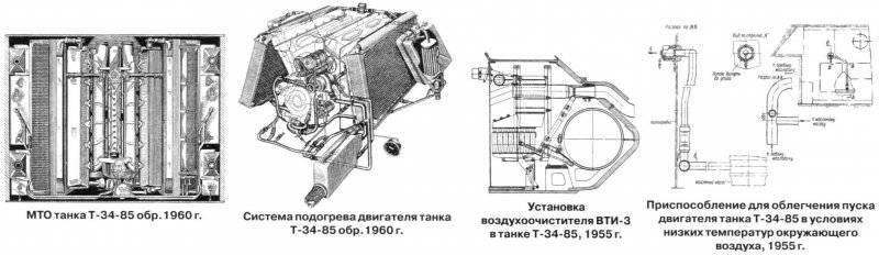
During the overhaul, instead of the B-2-34 engine, the B2-34М or В34М-11 diesel engine was installed with 368 kW power (500 hp) at a crankshaft speed of 1800 min-1. The engine was started using the ST-700 electric starter with a power of 11 kW (15 hp) (main mode) or compressed air (spare mode) from two ten-liter air cylinders. To facilitate engine start-up at low ambient temperatures with 1955, a nozzle heater with a water-tube boiler included in the cooling system was used, as well as a heater for heating the air entering the engine cylinders. The pumping unit of the heater was mounted on a bracket to the partition of the engine compartment. The heating system, in addition to the nozzle heater, included radiators for heating the oil in the right and left oil tanks, pipelines and electrical equipment (glow plugs and electric wires). The preheating system prepared the engine for start-up by warming up the coolant and some of the oil in the oil tanks. In addition, with 1957, in order to facilitate engine start-up at low ambient temperatures, an additional device was also used, which was designed to remove frozen oil from the oil pipe that supplies oil to the injection section of the oil pump 170.

The fuel system consisted of eight fuel tanks located inside the tank hull and grouped into three groups: a group of right-hand side tanks, a group of left-side side tanks and a group of stern tanks. The total capacity of all internal fuel tanks - 545 l. Additionally, on the right side of the tank were installed two external fuel tanks with a capacity of 90 l each. On the upper inclined stern sheet provided for mounting for two additional fuel tanks with a capacity of 67,5 l each (instead of smoke bombs). External fuel tanks were not included in the fuel system. A fuel (gear) pump was used to fuel the fuel tanks of the car from various tanks.
From 1960, two barrels for fuel with a capacity of 200 l each were mounted on the stern inclined sheet, and a drain tank was introduced into the fuel system. This tank was located on the MTO partition at the starboard side of the hull and served to drain fuel into it (through a special pipeline) from the crankcase of the fuel pump that had leaked through the gaps in the plunger pairs. At the same time, a small-sized MZA-3 filling unit was inserted into the spare parts kit of the tank, which was placed in a transport position in a metal box that was mounted outside on the left inclined side of the hull.
Cruising the tank on the highway on the main (internal) fuel tanks reached 300-400 km, on dirt roads - 230-320 km.
In the air cleaning system before 1946, two Cyclone air cleaners were used, then Multi-cyclone, and starting from 1955, two VTI-3 air cleaners of the combined type with automatic (ejection) removal of dust from the first stage dust collector were used. Ejectors, which ensured the removal of dust and connected to dust collectors, were mounted in the exhaust pipes of the engine. Each VTI-3 air cleaner consisted of a casing, a cyclone apparatus (cyclone 24) with a dust collector, a cover and a casing complete with three cassettes made of wire. New air cleaners were installed in the transmission compartment in place of the air cleaners of the previous design.
The combined circulation (under pressure and spraying) engine lubrication system (MT-16p oil was used) with a dry crankcase consisted of two oil tanks, an oil three-section gear pump, an oil slot-filter Kimaf, a tubular oil radiator, an equalizing tank, a manual oil pumping pump (with 1955, instead of it was used oil pump MZN-2 with electromotive drive), pipelines, pressure gauge and thermometer. Between the oil tanks and the engine on each side were water cooling system radiators. The oil radiator, which served to cool the oil coming out of the engine, was attached to the racks of the left water radiator with two bolts. Under conditions of low ambient air temperatures, the oil radiator was disconnected from the lubrication system using a special pipeline (carried in a spare parts kit). In this case, the oil from the pumping sections of the oil pump flowed directly into the surge tank, and then into the tanks.
The total filling capacity of the lubrication system up to 1955 was 105 l, while the filling capacity of each oil tank was equal to 40 l. With the introduction of a nozzle heater to heat the oil before starting the engine at low ambient temperatures, special radiators were placed in the oil tanks, which resulted in a decrease in the filling capacity of each tank to 38 l and, accordingly, the full filling capacity of the entire system to 100 l. In addition, an external oil tank with a capacity of 90 l, which is not connected to the engine lubrication system, was installed on the left side of the tank.


Engine cooling system - liquid, forced, closed type. The total cooling surface of each core of the radiator was 53 м2. Before 1955, the capacity of the cooling system was 80 l. Installation (with constant inclusion in the cooling system) of a heating system with a nozzle heater increased the system capacity to 95 l. To reduce the time to prepare the engine for start-up at low ambient temperatures with 1956, an additional filler neck was introduced in the cooling system. The hot liquid poured into this neck flowed directly into the heads and further into the notch space of the engine blocks, thereby accelerating its heating.
Knots and units of transmission and a running gear at major repairs were not exposed to essential changes. The structure of the mechanical transmission of the tank included: multi-disc main friction dry friction (steel on steel), four or five-speed gearbox 171, two multi-disk side friction dry friction (steel on steel) with tape, floating brakes with cast iron lining and two single-row gear bearers . In the gearboxes manufactured with 1954 and installed during the overhaul process, the oil drain hole in the lower half of the crankcase was closed with a drain valve. In addition to the gland, an oil slinger was additionally inserted between the adapter bushing and the tapered roller bearing of the gearbox drive shaft. The leakage of grease through the main shaft supports was prevented by sealing rings and an oil deflector.
Minor changes have undergone and the design of the clutches. In the tanks of the last year of release, the separator was not installed in the shutdown mechanism, and the grooves in the shutdown rings were made deeper.
In the undercarriage of the tank, an individual spring suspension was used, the nodes of which were located inside the tank hull. The suspension of the first track roller (as applied to one board), located in the control room, was fenced with a special shield, the suspension of the second, third, fourth and fifth track rollers was inclined in special mines.
The crawler propulsion unit had two large-caterpillar tracks, ten support rollers with external cushioning, two guide wheels with caterpillar tension mechanisms, and two drive wheels with tongue-and-groove engagement with the tracks. Two types of road wheels could be installed on the machine: with stamped or cast wheels with massive external rubber tires, as well as T-54A tank wheels with box-type wheels.
The electrical equipment of the machine was made on a single-wire scheme (emergency lighting - two-wire). The voltage of the onboard network was 24-29 B (starter circuit with starting relay and BCH) and 12 B (other users). The main source of electricity up to 1949 was a GT-4563 generator with a relay-regulator РРА-24Ф, then a G-731 generator with a power of 1,5 kW with a РРТ-30 relay-regulator, and four batteries: 6СТЭ-128 (used up to 1949 G.), 6MST-140 (up to 1955) and 6STEN-140М, connected in series in parallel, with a total capacity of, respectively, 256 and 280 Ah.


Prior to 1956, the VG-4 electric signal was installed on the bracket in front of the left side of the hull behind the exterior lighting, which was then replaced with the C-56 signal, and with the 1960, with the C-58 signal. With 1959, a second outdoor light was mounted on the right slope of the side sheet (with an infrared filter - FG-100). At the same time, the headlamp of FG-12B (left) was replaced with a headlight with a FG-102 blackout nozzle. In addition to the GTS-64 tail lamp, a similar marker lamp was introduced on the turret, next to which the headlight FG-1965 was located with the 126. To connect a portable lamp and a small filling unit MZN-3 in the rear part of the hull installed an external outlet.
The radio station 1952PC was used for external radio communication in the tank turret before 9, and the intercom for the intercom was TPU-3-Bis-F tank intercom. With 1952, the radio station 10РТ-26Е was used instead with a TPU-47 tank intercom. Subsequently, the radio station P-123 and the tank intercom P-124 were introduced, as well as an outlet for communication with the commander of the landing force.
The changes to the installation of spare parts, both outside and inside the tank.
RSB-F and 9PC172 radio stations with the TPU-3Bis-F tank intercom were installed on commander vehicles produced in the post-war period. The power supply of both radio stations was carried out from standard batteries. They were recharged using an autonomous charging unit, which included the L-3 / 2 engine. In connection with the installation of an additional radio station with a charging unit, the ammunition to the gun was reduced to 38 shots.
A part of the tanks was equipped for installing the PT-3 roller-track mine sweep.
On the basis of the T-34-85 tank in the post-war years, the T-34T tank tractor, SPK-5 tank crane (SPK-5 / 10М) and the KT-15 crane transporter were created and mass-produced at the overhaul of the USSR Defense Ministry. In addition, on the basis of the T-34-85, prototypes of tank cranes SPK-ZA and SPK-10 were made.
In 1947, the machine was assigned the factory designation "Object 135", and in the 1950s. it was repeatedly subjected to modernization, which was carried out at capital repair plants of the USSR Ministry of Defense. Modernization measures (aimed at improving the performance of combat and technical characteristics, improving the reliability of components and assemblies tank, convenience of its maintenance) on the instructions of GBTU developed CEZ No. 1 and VNII-100. The final development of the drawing-technical documentation for modernization, which was approved in 1960, was carried out by the design bureau of the plant No. 183 in Nizhny Tagil under the supervision of the chief designer L.N. Kartseva.
Tank T-34-85 arr. 1960 had a classic general layout with a crew of five and placement of internal equipment in four divisions: control, combat, engine, and transmission. Armored hull, turret, armament, power plant, transmission and undercarriage compared with the T-34-85 tank arr. 1944 did not undergo significant changes.
The department of management housed the workplaces of the driver (left) and the machine-gunner (right), the tank's controls, the DTM machine gun in a spherical installation, instrumentation, two compressed air cylinders, two hand-held fire extinguishers, a TPU apparatus, and part of the ammunition kit and spare parts. Landing and exit of the driver was made through the hatch, located in the upper front hull sheet and closed armor cover. In the lid of the driver's hatch there were two viewing instruments installed to increase the horizontal viewing angle at an angle to the longitudinal axis of the hatch with a turn towards the sides of the hull.


Tank T-34-85 arr. 1960
Combat weight - 32 t; crew - 5 people; weapon: gun - 85-mm rifled, 2 machine gun - 7,62-mm; armor protection - counterbalance; engine power 368 kW (HP 500); maximum speed on the highway - 60 km / h.
Combat weight - 32 t; crew - 5 people; weapon: gun - 85-mm rifled, 2 machine gun - 7,62-mm; armor protection - counterbalance; engine power 368 kW (HP 500); maximum speed on the highway - 60 km / h.

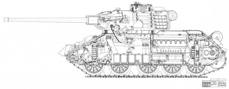
Longitudinal section of the T-34-85,1956 tank
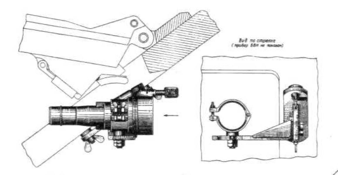

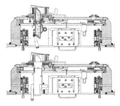
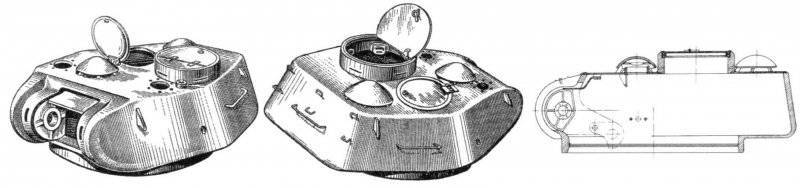
The commander's turret of the T-34-85 tank with the installation of the viewing device MK-4 (above) and TPK-1 (below) and the installation of the BVN night vision device from the driver-driver of the T-34-85 mod. 1960
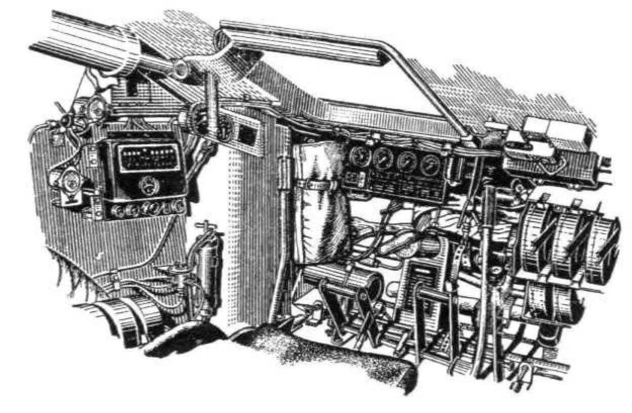
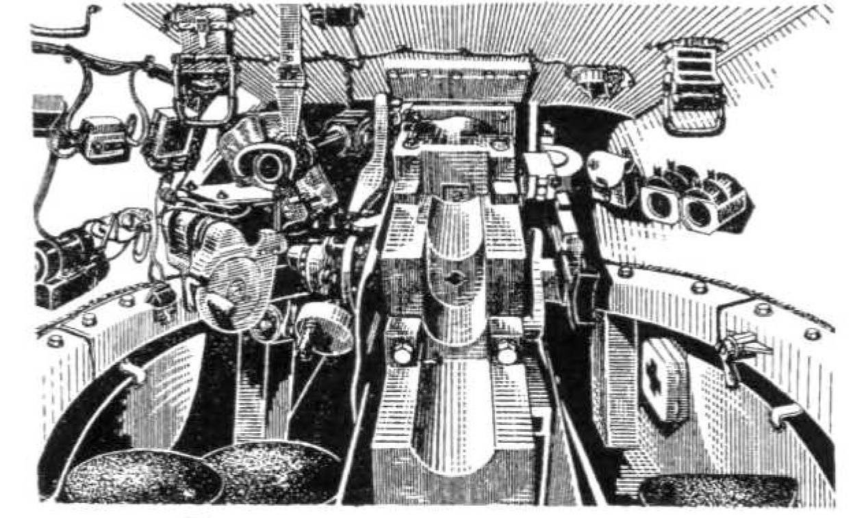
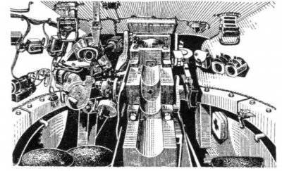
Office of the tank and the fighting compartment of the T-34-85 tank arr. 1960
When driving at night, the BVN night vision device was installed by the driver with the 1959 to monitor the road and terrain. In addition to the device itself, its kit included a high-voltage power supply unit, FG-100 headlight with an infrared filter and spare parts. In the off position, the BVN device and the instrument spare parts kit were stored in the packing box, which was located on the first box of the combat pack behind the driver’s seat. An additional optical element with an infrared filter was mounted on a bracket in the forward part of the body. When used, the BVN device was mounted in a removable bracket mounted on the beams welded to the upper front plate on the right side of the driver's hatch (the driver's hatch cover was in the open position). The power supply of the device was placed on the bracket, on the left side of the tank, the headlight FG-100 with an infrared filter - on the right side of the hull. An optical element with a blackout nozzle was removed from the left headlight of FG-102, and an optical element with an infrared filter was used instead.
In the bottom of the control compartment, in front of the machine gunner’s seat, there was a spare hatch that was closed with an armor cover, which was folded down (on one loop).
In the fighting compartment, which occupied the middle part of the tank hull and the internal volume of the turret, were placed tank armament with aiming devices and aiming mechanisms, surveillance devices, some ammunition, communication equipment and jobs, to the left of the gunner and tank commander. Above the commander's seat, on the roof of the tower, was a non-rotating commander's turret, in the side walls of which there were five viewing slots with protective glass, providing him with a circular view, and an access hatch closed by an armor cover. In the rotary base of the commander's hatch to 1960, the periscope viewing device MK-4 was installed, instead of which the viewing device TPK-1 or TPKU-2B165 was then used. Above the workplaces of the loader and the gunner in the roof of the tower was installed on one rotary periscopic device MK-4. In addition to the access hatch in the commander’s turret, a hatch in the right side of the tower’s roof above the loading station was used to land the crew located in the turret. The hatch was closed with a folding (on one loop) armored cap.

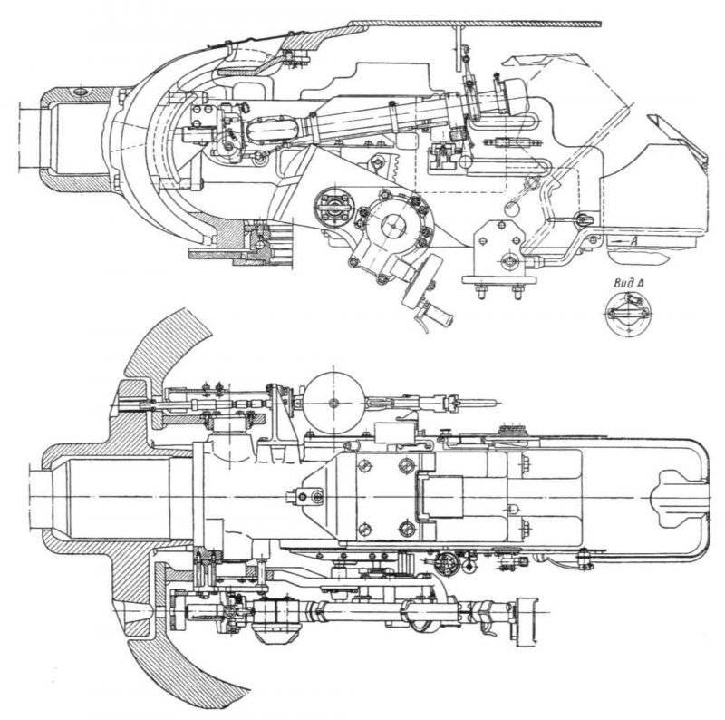
Installation of 85-mm gun ZIS-C-53 with a twin machine gun DTM in the tower of the T-34-85 tank arr. Xnumx

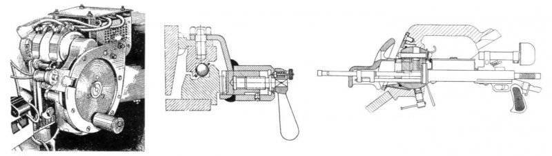
The rotation mechanism and the stopper of the tower, the installation of a frontal machine gun DTM tank T-34-85 rev.1960 g.
With 1955 in the fighting compartment at the left side of the tank mounted boiler nozzle heater, included in the engine cooling system.
The engine compartment was located behind the military and was separated from it by a removable partition. It housed the engine, two radiators and four batteries. When installing the heater in the upper removable and left non-removable sheets of the partition, a cutout was made for access to the heater supercharger, which was covered with a casing, and there was a window in the door of the side sheet for heater heater connections.
The transmission compartment was located in the rear part of the hull and was separated from the engine compartment by a partition. It installed the main clutch with a centrifugal fan and other transmission units, as well as electric starter, fuel tanks and air purifiers. The main weapon of the tank was the 85-mm tank gun ZIS-S-53 with a vertical wedge gate with semi-automatic mechanical (copy) type. The length of the barrel was 54,6 caliber, the height of the line of fire - 2020 mm. The 7,62 mm DTM machine gun was paired with a gun. The aiming of the paired installation in the vertical plane was carried out using a sector-type lifting mechanism ranging from -5 ° to + 22 °. The innocent space when firing from a cannon and a paired machine gun was 23 m. To protect the lifting mechanism from dynamic loads during the march inside the tower, to the left of the gun, the stopper of the stowed position of the gun was placed on the bracket, which fixed the gun in two positions: at an elevation angle 0 and 16 °.
For aiming a paired installation in the horizontal plane served as the BCH, located in the tower on the left side of the gunner's seat. The design of the BCH ensured the rotation of the tower using both manual and electromotive actuators. When using an electric motor drive, in which the MB-20B electric motor with a power of 1,35 kW was used, the turret was rotated at two different speeds in both directions, while the maximum speed reached 30 degrees / s.
On the part of the cars of the last year of release, instead of the two-speed electric drive of the turret rotation, a new KR-31 electric drive with commander control was used. This drive ensured the rotation of the turret both from the position of the gunner and from the position of the tank commander. The turn of the tower by the gunner was carried out using the KR-31 controller-rheostat. In this case, the direction of rotation of the tower corresponded to the deviation of the handle of the controller-rheostat to the left or right of the initial position. The speed of rotation depended on the angle of inclination of the handle of the controller from the initial position and varied over a wide range - from 2-2,5 to 24-26 degrees / s. The tank commander rotated the turret using the commander’s control system (target designation) by pressing a button mounted in the left grip of the commander’s viewing device. The tower was moved along the shortest path until the axis of the bore of the gun was aligned with the line of sight of the viewing device at a constant speed of 20-24 degrees / s. The stopping of the tower in the stowed position was carried out by a stopper of the tower, which was mounted on the right side (next to the loader's seat) in one of the grips of the ball bearing of the tower.
For conducting aimed fire from a cannon and a machine gun paired with it, adjusting the fire, determining the range to the targets and observing the battlefield, a telescopic articulated hinged sight TS-16 was used. The maximum sighting range of the gun was 5200 m, of the twin machine gun - 1500 m. To prevent the protective glass from misting, there was an electric heater. When shooting from a cannon from closed firing positions, a side level was applied, which was mounted on the left shield of the cannon fence, and a tower inclinometer (the indicator of the inclinometer was attached on the upper pursuit of the tower support to the left of the gunner's seat). The greatest range of fire from a cannon reached 13800 m.
The trigger mechanism of the gun consisted of both electric trigger and mechanical (manual) trigger. The electric control lever was located on the handle of the handwheel of the lifting mechanism, and the manual descent lever was located on the left shield of the cannon fence. Shooting from a coaxial machine gun was carried out using the same electric trigger lever. The switching on of the electric pulses was carried out with the help of toggle switches on the electric bullet board of the gunner.
The second 7,62-mm machine gun DTM was mounted in a ball mount, located in the right side of the upper front plate of the tank hull. The machine gun installation provided horizontal firing angles in the 12 ° sector and vertical guidance angles from -6 to + 16 °. When firing a machine gun used telescopic optical sight PPU-8T. The unobtainable space when firing from a frontal machine gun was 13 m.
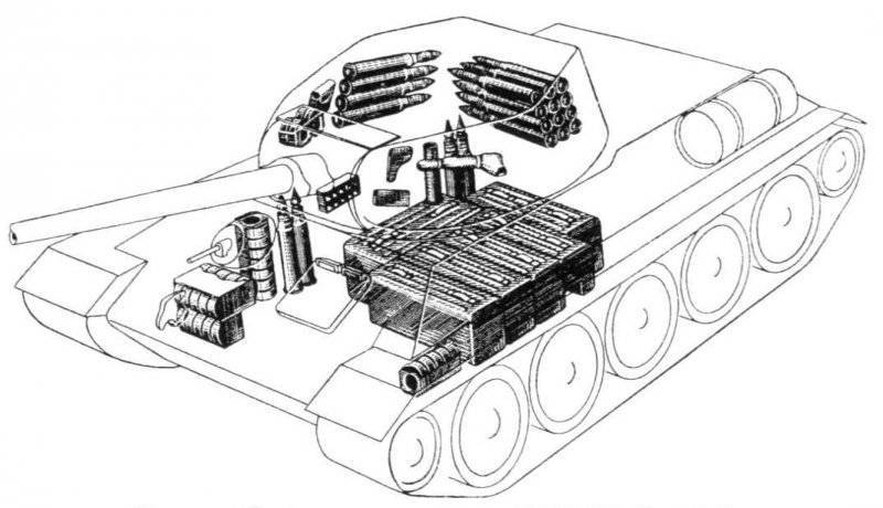
Laying ammunition in the tank T-34-85 arr. 1960
The tank ammunition to 1949 included from 55 to 60 shots 166 to the gun and 1890 cartridges (30 disks) to DTM machine guns. In addition, in the fighting compartment fit one 7,62-mm submachine gun PPSH with ammunition 300 cartridges (four disks), 20 hand grenades F-1 and 36 signaling rockets. In the period 1949-1956. the gun ammunition to the gun remained unchanged, instead of the PCA, the 7,62-mm AK-47 submachine gun with 300 ammunition ammunition (ten stores) was inserted, and instead of the signal flares, the 26-mm signal pistol with 20 signal cartridges.
The main rack stacking on 16 shots (in some tanks - 12 shots) was located in the turret niche, buckles for nine shots were placed: on board the hull (four shots), in the fighting compartment at the corners of the 167 partition (three shots), to the right in front of the combat the compartments (two shots), the remaining 35 shots (in some 34 tanks of the shot) were placed in six boxes on the bottom of the combat compartment. Disks for DTM machine guns were located in special sockets: 15 pcs. - On the front front plate in front of the machine gunner's seat, 7 pcs. - to the right of the machine gunner’s seat at the starboard of the hull, 5 pcs. - on the bottom of the case to the left of the driver's seat and 4 pcs. - on the right wall of the tower in front of the loader seat. The F-1 hand grenades were in laying nests, on the left side of the 168, next to them were the fuses in the bags.
For shooting from a gun, unitary shots were used with an BR-XNUM-AP armored-piercing trap-headed projecter with a ballistic tip and a BR-365K projectile projectile, with a brace armor-piercing tracer of a BR-365P projectile, and also with a small piece of a piece of a piece of a piece of a piece of a piece of a piece of a piece of equipment . The initial speed of the armor-piercing-tracer shell was 365 m / s, fragmentation grenades - 365 m / s at full charge and 895 m / s - at reduced charge. The range of the direct shot of the armor-piercing projectile was 900-600 m, the sabot armor-piercing tracer was 900 m (at the height of the target 950 m).
In 1956, the ammunition for the gun was brought to 60 shots (of which: 39 units with a high-explosive fragmentation projectile, 15 units with an armor-piercing tracer, and 6 units with a sub-caliber armor-piercing tracer), and to the machine guns DTM - up to 2750 cartridges, of which 1953 pcs. were in the 31 disk, and the rest were in the capping.
In 1960, the ammunition for the cannon was reduced to 55 shots to the cannon and 1890 cartridges for DTM machine guns. 12 shots (from O-365K) were in racking laying in the turret niche; eight shots were mounted in tie-in layouts: on the starboard of the tower (4 pieces from BR-365 or BR-365К), in the control section at the starboard of the hull (2 pieces with BR-365P) and in the right rear corner of the combat compartment (2 pieces with BR-365П). The remaining 35 shots (of which 24 units with О-365К, 10 units - with БР-365 or БР-365К and 1 units - with БР-365П) were placed in six boxes on the bottom of the fighting compartment. Laying cartridges for machine guns DTM and hand grenades F-1 has not changed. Cartridges for the AK-47 submachine gun in the amount of 180 units, equipped in six stores, were located: five stores in a special bag on the starboard side of the tower and one store - in a special pocket on the cover of the machine gun. The rest of the 120 cartridges in the standard capping fit in the tank at the discretion of the crew. Signal cartridges in the amount of 6 pcs. were in a special bag (under a holster with a signal pistol), on the left side of the turret to the left of the TSh sight, the rest of the 14 pieces. - in capping, in the fighting compartment in the empty places at the discretion of the crew.
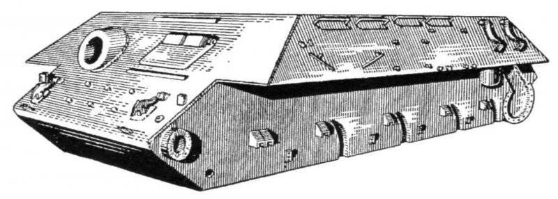
The armor protection of the tank - differentiated, protivosnaryadnaya. The design of the hull and turret of the tank compared with the T-34-85 tank arr. 1944 remained unchanged. The hull of the tank was welded from cast and rolled armor with thickness 20 and 45 mm with separate bolted joints.

T-34-85 tank body arr. 1960

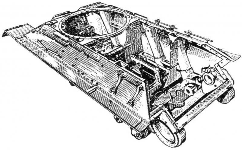
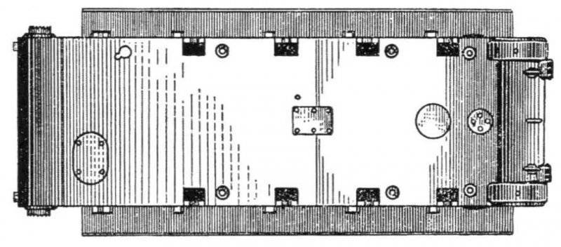
The bottom of the hull of the tank T-34-85 arr. 1960

T-34-85 tank tower arr. 1960 with improved ventilation system (longitudinal section).
The cast tower with welded roof, mounted on the tank hull on a ball bearing, had a maximum thickness in the frontal part of 75 mm - for cars of release up to 7 August 1944 g. Or 90 mm - for machines of late release. In the post-war tanks, towers were installed with an improved 169 ventilation system in the combat compartment. Installation of two exhaust fans, located in the aft roof of the tower, was posted. At the same time, one of the fans installed in the front part of the roof (above the cut of the breech of the gun) worked as an exhaust, and the second one, which remained in the same place, as the discharge, which allowed for a more efficient purge of the fighting compartment with the exception of crew seats.
For setting the smoke screen on the upper stern sheet of the machine body, two smoke bays BDSh-5 with electric ignition system from the place of the tank commander and the reset mechanism were installed. In the stowed position (when two additional fuel barrels were mounted on the tank, mounted on the upper stern sheet on special brackets) smoke bombs were mounted on the left upper side sheet, in front of the additional oil tank (on the part of the machines the third additional tank for 90 fuel was installed l).
During the overhaul, instead of the B-2-34 engine, the B2-34М or В34М-11 diesel engine was installed with 368 kW power (500 hp) at a crankshaft speed of 1800 min-1. The engine was started using the ST-700 electric starter with a power of 11 kW (15 hp) (main mode) or compressed air (spare mode) from two ten-liter air cylinders. To facilitate engine start-up at low ambient temperatures with 1955, a nozzle heater with a water-tube boiler included in the cooling system was used, as well as a heater for heating the air entering the engine cylinders. The pumping unit of the heater was mounted on a bracket to the partition of the engine compartment. The heating system, in addition to the nozzle heater, included radiators for heating the oil in the right and left oil tanks, pipelines and electrical equipment (glow plugs and electric wires). The preheating system prepared the engine for start-up by warming up the coolant and some of the oil in the oil tanks. In addition, with 1957, in order to facilitate engine start-up at low ambient temperatures, an additional device was also used, which was designed to remove frozen oil from the oil pipe that supplies oil to the injection section of the oil pump 170.

Tank T-34-85 arr. 1960 g. On the left side of the hull, the mounting of smoke bombs BBSH-5 are clearly visible.

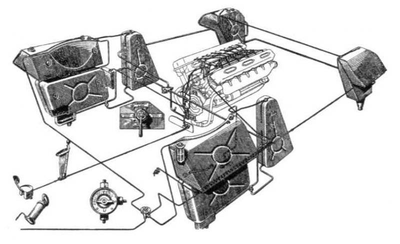
The fuel system of the engine tank T-34-85 arr. 1960

The fuel system consisted of eight fuel tanks located inside the tank hull and grouped into three groups: a group of right-hand side tanks, a group of left-side side tanks and a group of stern tanks. The total capacity of all internal fuel tanks - 545 l. Additionally, on the right side of the tank were installed two external fuel tanks with a capacity of 90 l each. On the upper inclined stern sheet provided for mounting for two additional fuel tanks with a capacity of 67,5 l each (instead of smoke bombs). External fuel tanks were not included in the fuel system. A fuel (gear) pump was used to fuel the fuel tanks of the car from various tanks.
From 1960, two barrels for fuel with a capacity of 200 l each were mounted on the stern inclined sheet, and a drain tank was introduced into the fuel system. This tank was located on the MTO partition at the starboard side of the hull and served to drain fuel into it (through a special pipeline) from the crankcase of the fuel pump that had leaked through the gaps in the plunger pairs. At the same time, a small-sized MZA-3 filling unit was inserted into the spare parts kit of the tank, which was placed in a transport position in a metal box that was mounted outside on the left inclined side of the hull.
Cruising the tank on the highway on the main (internal) fuel tanks reached 300-400 km, on dirt roads - 230-320 km.
In the air cleaning system before 1946, two Cyclone air cleaners were used, then Multi-cyclone, and starting from 1955, two VTI-3 air cleaners of the combined type with automatic (ejection) removal of dust from the first stage dust collector were used. Ejectors, which ensured the removal of dust and connected to dust collectors, were mounted in the exhaust pipes of the engine. Each VTI-3 air cleaner consisted of a casing, a cyclone apparatus (cyclone 24) with a dust collector, a cover and a casing complete with three cassettes made of wire. New air cleaners were installed in the transmission compartment in place of the air cleaners of the previous design.
The combined circulation (under pressure and spraying) engine lubrication system (MT-16p oil was used) with a dry crankcase consisted of two oil tanks, an oil three-section gear pump, an oil slot-filter Kimaf, a tubular oil radiator, an equalizing tank, a manual oil pumping pump (with 1955, instead of it was used oil pump MZN-2 with electromotive drive), pipelines, pressure gauge and thermometer. Between the oil tanks and the engine on each side were water cooling system radiators. The oil radiator, which served to cool the oil coming out of the engine, was attached to the racks of the left water radiator with two bolts. Under conditions of low ambient air temperatures, the oil radiator was disconnected from the lubrication system using a special pipeline (carried in a spare parts kit). In this case, the oil from the pumping sections of the oil pump flowed directly into the surge tank, and then into the tanks.
The total filling capacity of the lubrication system up to 1955 was 105 l, while the filling capacity of each oil tank was equal to 40 l. With the introduction of a nozzle heater to heat the oil before starting the engine at low ambient temperatures, special radiators were placed in the oil tanks, which resulted in a decrease in the filling capacity of each tank to 38 l and, accordingly, the full filling capacity of the entire system to 100 l. In addition, an external oil tank with a capacity of 90 l, which is not connected to the engine lubrication system, was installed on the left side of the tank.

Placement of electrical equipment in the turret and hull of the T-34-85 tank rev.xnumx
Engine cooling system - liquid, forced, closed type. The total cooling surface of each core of the radiator was 53 м2. Before 1955, the capacity of the cooling system was 80 l. Installation (with constant inclusion in the cooling system) of a heating system with a nozzle heater increased the system capacity to 95 l. To reduce the time to prepare the engine for start-up at low ambient temperatures with 1956, an additional filler neck was introduced in the cooling system. The hot liquid poured into this neck flowed directly into the heads and further into the notch space of the engine blocks, thereby accelerating its heating.
Knots and units of transmission and a running gear at major repairs were not exposed to essential changes. The structure of the mechanical transmission of the tank included: multi-disc main friction dry friction (steel on steel), four or five-speed gearbox 171, two multi-disk side friction dry friction (steel on steel) with tape, floating brakes with cast iron lining and two single-row gear bearers . In the gearboxes manufactured with 1954 and installed during the overhaul process, the oil drain hole in the lower half of the crankcase was closed with a drain valve. In addition to the gland, an oil slinger was additionally inserted between the adapter bushing and the tapered roller bearing of the gearbox drive shaft. The leakage of grease through the main shaft supports was prevented by sealing rings and an oil deflector.
Minor changes have undergone and the design of the clutches. In the tanks of the last year of release, the separator was not installed in the shutdown mechanism, and the grooves in the shutdown rings were made deeper.
In the undercarriage of the tank, an individual spring suspension was used, the nodes of which were located inside the tank hull. The suspension of the first track roller (as applied to one board), located in the control room, was fenced with a special shield, the suspension of the second, third, fourth and fifth track rollers was inclined in special mines.
The crawler propulsion unit had two large-caterpillar tracks, ten support rollers with external cushioning, two guide wheels with caterpillar tension mechanisms, and two drive wheels with tongue-and-groove engagement with the tracks. Two types of road wheels could be installed on the machine: with stamped or cast wheels with massive external rubber tires, as well as T-54A tank wheels with box-type wheels.
The electrical equipment of the machine was made on a single-wire scheme (emergency lighting - two-wire). The voltage of the onboard network was 24-29 B (starter circuit with starting relay and BCH) and 12 B (other users). The main source of electricity up to 1949 was a GT-4563 generator with a relay-regulator РРА-24Ф, then a G-731 generator with a power of 1,5 kW with a РРТ-30 relay-regulator, and four batteries: 6СТЭ-128 (used up to 1949 G.), 6MST-140 (up to 1955) and 6STEN-140М, connected in series in parallel, with a total capacity of, respectively, 256 and 280 Ah.
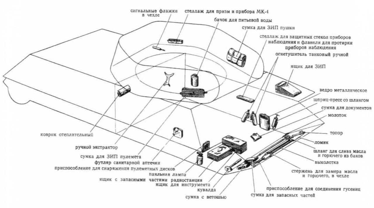
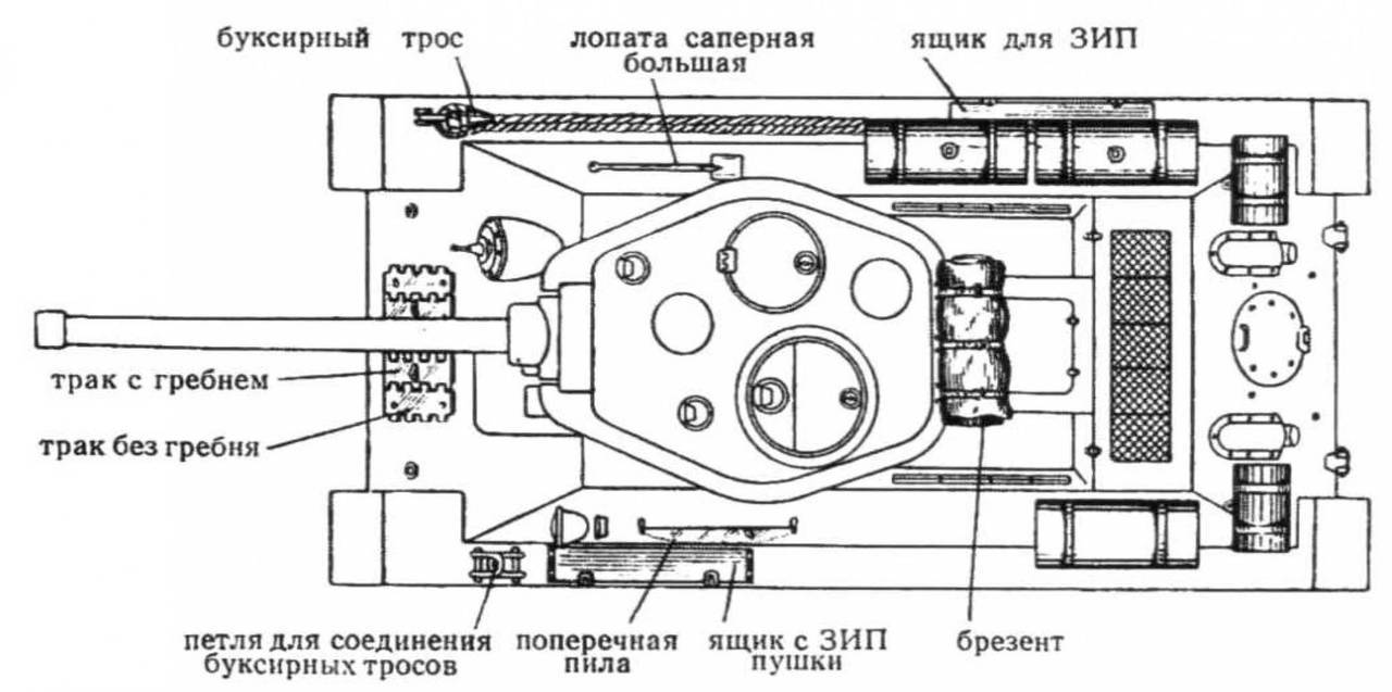
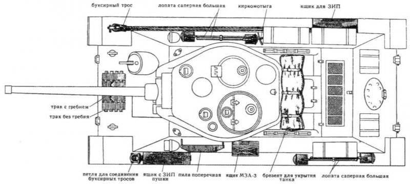
Placement of spare parts inside and outside (below) tank T-34-85,1956
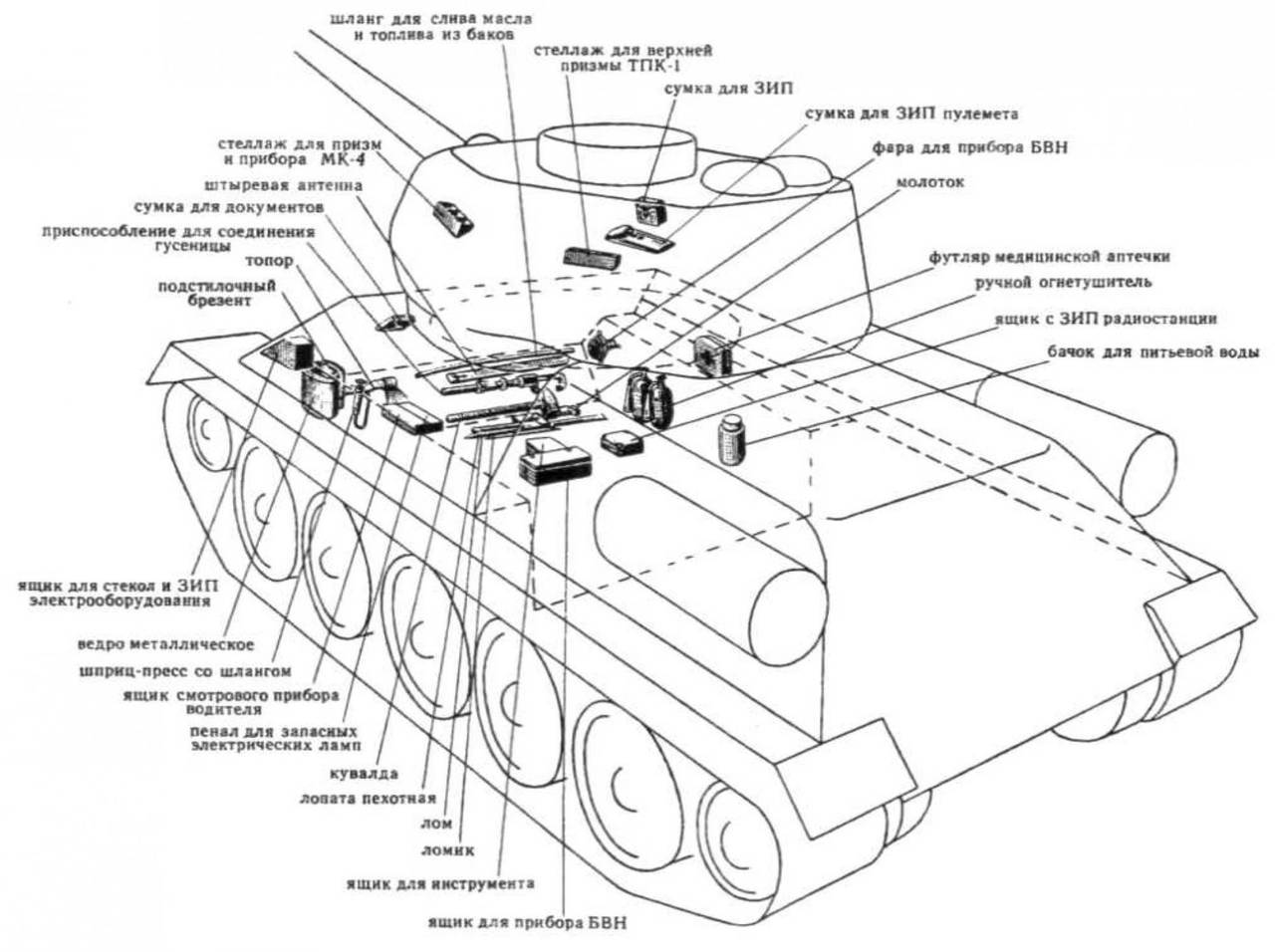
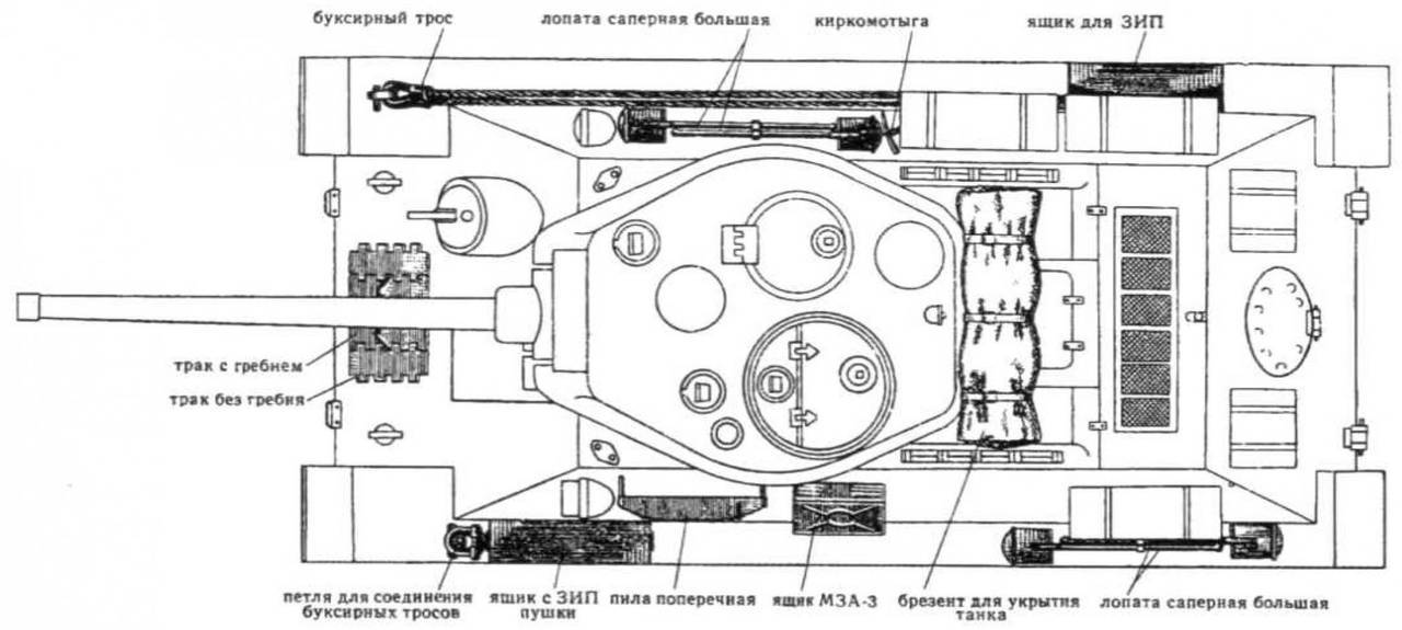
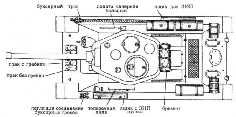
Placement of spare parts inside and outside (below) the T-34-85 tank arr. 1960
Prior to 1956, the VG-4 electric signal was installed on the bracket in front of the left side of the hull behind the exterior lighting, which was then replaced with the C-56 signal, and with the 1960, with the C-58 signal. With 1959, a second outdoor light was mounted on the right slope of the side sheet (with an infrared filter - FG-100). At the same time, the headlamp of FG-12B (left) was replaced with a headlight with a FG-102 blackout nozzle. In addition to the GTS-64 tail lamp, a similar marker lamp was introduced on the turret, next to which the headlight FG-1965 was located with the 126. To connect a portable lamp and a small filling unit MZN-3 in the rear part of the hull installed an external outlet.
The radio station 1952PC was used for external radio communication in the tank turret before 9, and the intercom for the intercom was TPU-3-Bis-F tank intercom. With 1952, the radio station 10РТ-26Е was used instead with a TPU-47 tank intercom. Subsequently, the radio station P-123 and the tank intercom P-124 were introduced, as well as an outlet for communication with the commander of the landing force.
The changes to the installation of spare parts, both outside and inside the tank.
RSB-F and 9PC172 radio stations with the TPU-3Bis-F tank intercom were installed on commander vehicles produced in the post-war period. The power supply of both radio stations was carried out from standard batteries. They were recharged using an autonomous charging unit, which included the L-3 / 2 engine. In connection with the installation of an additional radio station with a charging unit, the ammunition to the gun was reduced to 38 shots.
A part of the tanks was equipped for installing the PT-3 roller-track mine sweep.
On the basis of the T-34-85 tank in the post-war years, the T-34T tank tractor, SPK-5 tank crane (SPK-5 / 10М) and the KT-15 crane transporter were created and mass-produced at the overhaul of the USSR Defense Ministry. In addition, on the basis of the T-34-85, prototypes of tank cranes SPK-ZA and SPK-10 were made.
- Mv Pavlov, Candidate of Technical Sciences, Senior Researcher I. V. Pavlov, Lead Designer, "Equipment and Weapons"
- Modernized medium tanks in the postwar period. Tank T-34-85 arr. Xnumx.
Modernized medium tanks in the postwar period. Tank T-44M
Heavy tanks of the USSR in the postwar period
Middle tanks in the postwar period. "432 Object"
Information