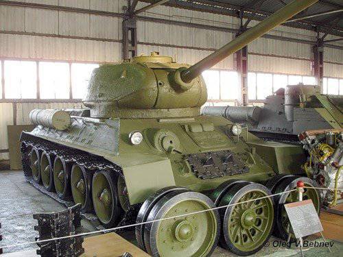
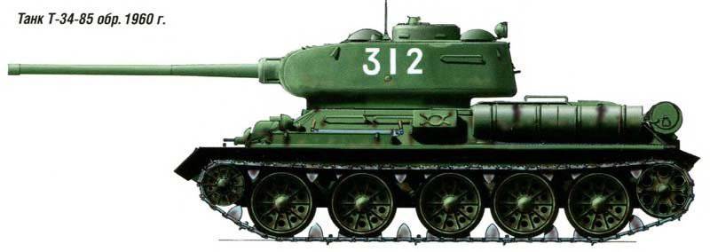
Experienced tank T-34-85 model 1960, "Object 135"
History create
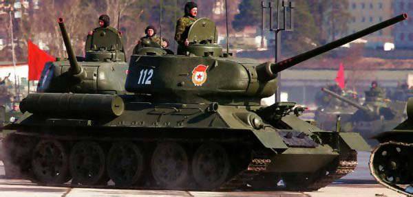
The T-34-85 tank of the 1960 model is an advanced model tank T-34-85 model 1944. T-34-85 period of the Great Patriotic War, developed in the design bureau of the Gorky factory number 112 "Red Sormovo". The development was led by the chief designer of the plant V.V. Krylov Subsequently, the technical documentation for the machine was approved by the parent plant No. 183 in Nizhny Tagil (chief designer - A. Morozov). January 23, 1944 by the decree of GKO No. 5020, the tank was adopted by the Red Army. Production of these tanks was carried out at factories No. 112 Krasnoye Sormovo, No. 174 (Omsk) and No. 183 between March 1944 and December 1946. In the post-war period, factories produced 5742 tanks.
In 1947, the car was given the factory designation "Object 135". In 1950's, it has been repeatedly upgraded. Modernization activities were carried out at the overhaul plants of the USSR Ministry of Defense. These activities (the purpose of which was to improve the technical and combat characteristics, increase the reliability of the units and units of the tank, ease of maintenance) developed VNII-100 and CEZ No. 1 on the instructions of the GBTU. The final development of the technical design documentation for the modernization, approved in 1960, was carried out under the supervision of the chief designer L. Kartsev. Design Bureau of the plant number XXUMX (Nizhny Tagil). The T-183-34 tank of the 85 model of the year had a classic general layout, the crew was five people. The internal equipment was located in the 1960-x compartments: transmission, engine, combat and control. Armored hull, turret, armament, undercarriage, transmission and power plant compared to the T-4-34 of the 85 model, did not undergo significant changes.
Layout and equipment
The control unit housed a machine gunner (right) and a driver (left), a DTM machine gun mounted in a ball mount, tank controls, test equipment, two hand-held fire extinguishers, two compressed air cylinders, a TPU machine, and spare parts and accessories. ammunition. The driver entered the car through the hatch, which was located in the upper front plate of the armored hull and was closed with an armor cover. The driver's hatch cover was equipped with two viewing devices that served to increase the horizontal viewing angle (they were turned towards the sides of the hull). To monitor the terrain and the road in the dark, the driver had a night vision device BVN. The BVN kit consisted of the device itself, a high-voltage power supply unit, a FG-100 headlamp having an infrared filter and spare parts. The BVN device and spare parts to it in a non-working position were stored in the packing box, located behind the driver's seat on the first box of the ammo pack. In the forward part of the body an additional optical element with an infrared filter was attached to the bracket.
The BVN device, when used, was mounted in a removable bracket that was mounted on the beams welded to the upper front sheet on the right side of the hatch (the hatch cover was open). The power supply unit of the device was mounted on a bracket, inside the tank on the left side, on the right side of the hull - headlight FG-100 with an infrared filter. An optical element and a blackout nozzle were removed from the left FG-102, and instead of them, an optical element having an infrared filter was used. In front of the machine gunner’s seat, there was a spare hatch in the bottom of the control compartment, which was closed by folding down the armor cover (one loop was used).
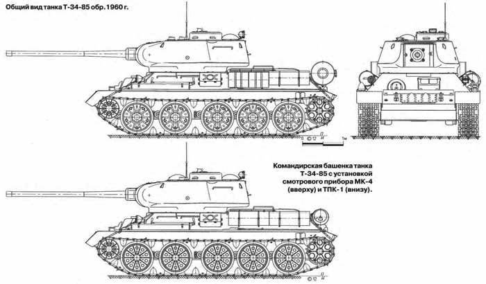
In the fighting compartment, which occupied the middle part of the hull and the internal volume of the turret, were tank armament with aiming mechanisms and aiming devices, observation devices, communications equipment and part of the ammunition, as well as jobs, the tank commander and gunner - to the left of the gun, the loader - to the right . On the roof of the tower above the commander's seat was a non-rotating commander's turret. The side walls of the turret had five viewing slots (protected by glass), which provided the commander with a circular view. In the turret roof there was an access hatch that was closed with an armored cover. In the rotary base of the hatch was installed viewing device TPKU-2B or TPK-1. In the roof of the tower above the workplaces of the gunner and loader, one periscopic rotary device MK-4 was installed. In addition to the access hatch in the commander’s turret, a crew hatch was used to land the crew, which was made above the work area of the loader in the right side of the tower’s roof. The hatch was closed with a hinged armor cover on one loop.
At the left side in the fighting compartment of the tank was mounted boiler nozzle heater, which was included in the engine cooling system. Behind the fighting compartment was located the engine compartment. They were separated by a removable partition. The engine compartment housed the engine, four batteries and two radiators. In the left fixed and upper removable sheets made a cut to access the heater supercharger, closed the casing. In the door of the side sheet there was a window for heater tubes. At the rear of the hull there was a transmission compartment, separated by a partition from the engine compartment. The main friction clutch with a centrifugal fan, transmission units, air cleaners, fuel tanks and electric starter were installed in it.
Armament and sighting devices
The basic one weapons The T-34-85 of the 1960 model of the year was a ZIS-C-53 tank gun of the 85 mm caliber with a semi-automatic mechanical (copy) type and a vertical wedge gate. The length of the barrel - 54,6 caliber, the height of the line of fire - 2,02 m. With a ZIS-C-53 cannon, a DTM machine gun of 7,62 mm caliber was paired. In the vertical plane, the aiming of the coupled unit was carried out in the range from -5 to + 22 degrees using a sector-type lifting mechanism. The unobtainable space when firing from a twin installation was 23 meters. To protect the lifting mechanism during the march from dynamic loads on the bracket, to the left of the gun, inside the turret there was a stopper of the stowed position of the gun, ensuring the fixation of the gun in two positions (elevation angles - 16 and 0 degrees). In the horizontal plane, the aiming of the coupled unit was carried out by the BCH, located on the left of the gunner's seat in the tower. The design of the rotation mechanism of the tower ensured rotation using an electromotive or manual drive. When using an electromotor drive (1,35-kilowatt motor MB-20B was used), the turret turned in both directions with two different speeds. The maximum speed of rotation of the tower in this case was 30 degrees per second.
On the part of the T-34-85 tanks of the last year of production, the two-speed electric turret rotation was replaced by the new KR-31 electric drive. This drive ensured the rotation of the tower from the gunner’s place or from the place of the commander. The turn of the tower by the gunner was carried out using the KR-31 controller-rheostat. The direction of rotation of the tower in this case corresponded to the deviation of the handle to the right or to the left from the initial position. The speed of rotation was set by the angle of inclination of the handle of the controller and varied within the limits - from 2 to 26 degrees per second. The tank commander turned the turret using the command and control system by pressing a button that was mounted in the left grip of the commander’s viewing instrument. The tower was moved along the shortest path until the axis of the bore and the line of sight of the viewing device were combined. Speed - 20-24 degrees per second. In the stowed position, the tower was locked using a tower stopper mounted on the right side (near the loader's seat) in one of the grips of the ball bearing of the tower.
For observation of the battlefield, determination of the range to the targets, aimed fire from a cannon and a coaxial machine gun, fire correction, a tank hinged telescopic sight TS-16 was used. The maximum range of aimed fire from a cannon is 5,2 thousand m, from a twin machine gun - 1,5 thousand m. To prevent fogging of the glass of the sight, it was equipped with an electric heater. When firing from a cannon from closed firing positions, a side level was used, mounted on the left shield of the cannon fence, as well as a tower inclinometer (the pointer was attached to the left of the gunner’s seat on the upper chase of the tower support). The maximum firing range of the gun - 13,8 thousand meters. The trigger mechanism of the gun included electric trigger and manual (mechanical) trigger. The lever of the electric trigger was located on the handle of the handwheel of the lifting mechanism, the lever of manual descent - on the left guard of the fence. The fire from the coaxial machine gun was made with the help of the same electric trigger lever. Switching / switching on of the electric pulses was carried out by toggle switches on the gunner's electric pulses.
The second DTM machine gun, caliber 7,62 mm, was installed in a ball mount on the right side of the frontal top sheet of the hull of the T-34-85 tank. The machine-gun installation provided the corners of vertical pickup in the range from -6 to + 16 degrees, horizontal angles - in the sector 12 degrees. When firing from this machine gun, an optical telescopic sight PPU-8T was used. When firing from a frontal machine gun, the innocent space was 13 meters. Ammunition guns consisted of 55 - 60 shots, machine guns DTM - 1890 cartridges (30 discs). In addition, the fighting compartment was equipped with: AK-47 automatic rifle caliber 7,62 mm (ammunition 300 ammunition, 10 shops), 20 hand grenades F-1, 26-mm signal pistol (20 signal cartridges).
Ammunition
For firing from a cannon, unitary shots with the following shells were used: a stupid, armored-piercing tracer BR-365 with a ballistic tip; sharp-headed BR-365K; subcaliber armor-piercing tracer BR-365P; as well as with a reduced-charge and full charge one-piece 0-365K fragmentation grenade. The armor-piercing tracer had an initial speed of 895 m / s, a fragmentation grenade with a full charge - 900 m / s and with a reduced charge - 600 m / s. The range of a direct shot at a target with a height of 2 meters when using an armor-piercing projectile is 900-950 meters, and a sub-caliber armor-piercing tracer is 1100 meters.
The main racking, consisting of 12 shots (O-365K), was located in a niche of the tower. Tightening styling, 8 shots, were placed: 4 shot (BR-365 or BR-365К) - on the right side of the corps in the fighting compartment; 2 shot (BR-365P) - at the corners of the partition in the fighting compartment; 2 shot (BR-365P) - in front of the crew compartment on the right. The remaining 35 shots (24 O-365K, 10 BR-365 or BR-365K and 1 BR-365P) were placed in six boxes in the fighting compartment at the bottom.
Disks for machine guns located in the spec. sockets: in front of the machine gunner’s seat on the front front plate - 15 pcs, on the starboard side of the case to the right of the machine gunner’s seat - 7 pcs, to the left of the driver’s seat on the bottom of the case - 5 pcs, in front of the seat charging on the right wall of the tower - 4 pcs. Hand grenades F-1 and fuses in bags were located on the left side in laying nests.
The cartridges for AK-47 (180 pieces), equipped in 6 stores, were located in: specials. bag on the starboard tower - 5 stores; On the cover of the machine in a special pocket - 1 store. The rest of the cartridges (120 pcs.) In the standard closure fit at the discretion of the crew. 6 signal cartridges were in spec. the bag, to the left of the TSh sight on the left side of the turret, the rest of the 14 cartridges were placed in the closure at the discretion of the crew in free places in the fighting compartment.
Shell and Tower
The armor protection of the tank - protivosnaryadnaya, differentiated. The design of the hull and tower compared with the T-34-85 model 1944, remained unchanged. The hull of the tank was welded from katana and cast armor with a thickness of 20 and 45 millimeters with separate bolted joints. The cast turret, which has a welded roof, was mounted on the tank hull using a ball bearing. The maximum thickness in the frontal part is 90 millimeters. On the T-34-85 tank of the 1960 model of the year, towers were installed with an improved ventilation system in the crew compartment. Installation of two exhaust fans smashed. In this case, one fan, installed above the cut of the breech of the gun in the front of the roof, served as an exhaust fan, and the second, installed in the aft part of the tower roof, was the discharge. This placement of the fans made it possible to increase the efficiency of blowing the fighting compartment and eliminate the passage of gases generated during the combustion of gunpowder through crew jobs. On the upper hull stern sheet for setting up a smoke screen, 2 smoke bays BDSH-5 with a reset mechanism and an electrical ignition system (from the commander’s place) were installed. In the stowed position (in the case of installation of two additional barrels of fuel mounted on special brackets on the upper stern plate) smoke bombs were mounted on the left upper side plate, in front of the additional oil tank (on some machines the third additional tank of 90 liters was installed) .
Engine and fuel system
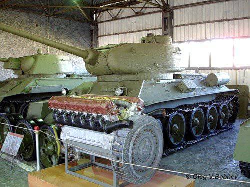
The T-34-85 of the 1960 model of the year was fitted with an 500-strong (with a crankshaft speed of 1800 rpm) B2-34М or B34М-11 diesel engine. The engine was started using the 15-strong electric starter CT-700 (the main starting method) or compressed air (a spare method) stored in two air tanks of 10 liters. To facilitate start-up at low temperatures, a nozzle heater with a water-tube boiler, which is included in the cooling system, and a heater for heating the air, which enters the engine cylinders, are used. The heater was attached to the partition of the engine compartment on the bracket. In addition to the spray heater, the heating system included oil heating radiators in both oil tanks, electrical equipment (electrical cables and glow plugs) and pipelines. The heating system provided the diesel engine with preparation for starting up by heating the coolant, as well as some of the oil in the tanks. In addition, to facilitate engine start-up at low temperatures, a device was used to remove frozen oil from the oil pipe leading it to the injection part of the oil pump.
The fuel system had 8 fuel tanks located inside the hull and grouped into 3 groups: a group of stern tanks, a group of right and left side tanks. The total capacity of the internal tanks - 545 liters. On the right side of the tank were installed two external additional fuel tanks for 90 liters each. External fuel tanks were not included in the fuel system. On an inclined stern sheet fastened two barrels with a capacity of 200 liters each. The fuel system included a drain tank located on the partition of the engine compartment at the starboard side of the hull and used to drain the fuel pump through a special fuel pipe. The tank spare parts kit included a small-sized MZA-3 filling unit, placed in a transport position in a metal box mounted outside on the inclined left side of the hull. The power reserve of the T-34-85 tank model 1960 of the year on the highway on the internal (main) fuel tanks - 300-400 kilometers, along dirt roads - up to 320 kilometers.
Engine cooling system - forced, liquid, closed type. Each core of the radiator had a cooling surface 53 meter. The capacity of the cooling system after the installation of the heating system (with constant inclusion in the system) with a nozzle heater was equal to 95 liters. To reduce the time to prepare the engine for start-up at low temperatures, the cooling system has a filler neck. The hot liquid poured into this neck flowed directly into the heads and the notch space of the engine blocks, thereby accelerating its heating.
Air cleaning system
In the air cleaning system, two combined-type VTI-3 air cleaners equipped with ejector automatic dust removal from the first stage of the dust collector were used. Ejectors connected to dust collectors were installed in the exhaust pipes of the engine. The air cleaner consisted of a casing, a cyclone apparatus with a dust collector, a cover and a casing with three cassettes of wire.
Lubrication system
The combined circulation (spray and under pressure) lubrication system of the engine with a dry crankcase (MT-16p oil was used) consisted of: three-section oil gear pump, two oil tanks, Kimaf oil wire-slot filter, equalizing tank, tubular oil radiator, oil pump pump MZN-2 with electric drive, thermometer, pressure gauge and pipelines. Between the engine and oil tanks on each side housed water radiators included in the cooling system. The oil radiator cooling the oil coming out of the engine was fastened with two bolts to the posts of the left water radiator. Under low temperature conditions, the oil radiator was disconnected from the lubrication system with the help of a special pipeline (used to be in a spare parts kit). In this case, oil flowed directly into the surge tank, and then into the tanks.
The total filling capacity of the entire T-34-85 lubrication system of the 1960 sample of the year was 100 liters. Each oil tank included 38 liters of oil. In the lubrication system there was a nozzle heater to heat the oil before starting the engine at low ambient temperatures and special radiators placed in oil tanks. On the left side of the T-34-85 of the 1960 model of the year, there was an external 90-liter oil tank that does not have a connection to the engine lubrication system.
Transmission and chassis
Components and units of the chassis and transmission are not significantly different from the T-34-85 model 1944 year. The mechanical transmission of the tank consists of: a multi-plate main friction clutch for dry friction (steel on steel), a four- or five-speed gearbox, two multidisk drive clutches with floating, band brakes with cast-iron linings, and two gear single-row bead reduction gears. The transmission in the lower half of the crankcase had a drain valve to drain the oil. Between the tapered roller bearing of the gearbox drive shaft and the adapter sleeve, in addition to the gland, there is an oil deflector. The leakage of grease through the main shaft supports was prevented by the oil deflector and the sealing rings.
In the undercarriage of the T-34-85 model 1960, an individual spring suspension was used, the nodes of which were located inside the tank hull. The suspension of the first road roller, located in the department of management, was protected by a special shield. The 2 - 4 track rollers suspended in special shafts obliquely. The crawler propulsion unit consisted of two large-caterpillar tracks, ten support rollers with external cushioning, two guide wheels equipped with caterpillar tension mechanisms, and two drive wheels of tongue-and-groove gearing. Two types of road wheels were installed on the machine: with cast or stamped discs with massive external rubber tires.
Electric equipment
The electrical equipment of the tank was performed using a single-wire circuit (in emergency lighting, a two-wire circuit was used). The onboard power supply voltage is 24-29 B (BCH and starter circuit with starting relay) and 12 B (other users). The main source of electricity was the X-NUMX-kilowatt G-1,5 generator with a relay regulator РРТ-731. Auxiliary - 30STEN-4М rechargeable batteries, which are interconnected in series with each other in parallel, with a total capacity of 6 and 140 Ah, respectively. The C-256 signal was mounted on the bracket in the front part of the inclined hull behind the outdoor lighting headlamp. On the right side slope of the sheet was mounted headlight outdoor lighting, having an infrared filter FG-280. The left headlight was equipped with a FG-58 blackout nozzle. In addition to the GTS-100 tail lamp, there was a similar marker lamp located on the turret, near which the headlight FG-102 was located. In order to connect the small MZN-64 filling unit and a portable lamp, an external receptacle was installed in the rear of the hull.
Communication devices
The P-123 radio station was used in the turret of the tank for external radio communication, and the P-124 tank intercom was used for intercom communications. For communication with the commander of the landing there was an outlet. On commander vehicles, the 9RS and RSB-F radio stations were installed, as well as the TPU-ZBis-F tank intercom. To power the radio stations were used regular batteries. The batteries were recharged using an autonomous charging unit, which included the L-3 / 2 engine.
Performance characteristics of the T-34-85 sample 1960 G .:
Combat weight - 32,5 - 33 tons;
Crew - 5 man;
DIMENSIONS:
Full length - 8100 mm;
Housing length - 6100 mm;
Width - 3000 mm;
Height - mm 2700;
Clearance - 400 mm;
ARMAMENT:
- gun C-53 caliber 85 mm;
- Two DTM machine guns caliber 7,62 mm;
BOECOMPLEKT:
- 56 shots;
- 1953 cartridge;
TARING TOOLS:
- telescopic sight TSH-16;
- machine gun telescopic sight PPU-8T;
RESERVATION:
Front of the tower - 90 mm;
side turret - 75 mm;
The forehead of the case is 45 mm;
hull bead - 45 mm;
roof - mm 16-20;
feed bottom - 40 mm;
feed top - 45 mm;
front sheet bottom - 20 mm;
rear sheet bottom - 13 mm;
ENGINE:
- B-2-34, 12-cylinder, diesel, liquid cooling, hp power 500 at 1700 rpm; tank capacity - 550 l .;
TRANSMISSION:
- mechanical, 5-speed gearbox (4 forward, 1 back), final drives, friction clutches;
CHASSIS (on board):
5 dual track rollers (diameter 830 mm), rear guide and front drive wheel; tracks - fine, steel, ridge engagement, 72 track in each track;
SPEED:
on the highway - 54 km \ h;
range on the highway - 290-300 km;
over rough terrain - 25 km / h;
range over the country road - 220-250 km;
OBTAINABLE OBSTACLES:
Rise - 35 degrees;
Descent - 40 degrees;
Wall height - 0,73 m;
The width of the moat - 2,50 m;
Wade depth - 1,30 m;
MEANS OF COMMUNICATION:
- intercom TPU-47;
- radio station 10-РТ-26Е.
Based on materials:
http://www.dogswar.ru
http://www.battlefield.ru/
http://www.aviarmor.net
The T-34-85 tank of the 1960 model is an advanced model tank T-34-85 model 1944. T-34-85 period of the Great Patriotic War, developed in the design bureau of the Gorky factory number 112 "Red Sormovo". The development was led by the chief designer of the plant V.V. Krylov Subsequently, the technical documentation for the machine was approved by the parent plant No. 183 in Nizhny Tagil (chief designer - A. Morozov). January 23, 1944 by the decree of GKO No. 5020, the tank was adopted by the Red Army. Production of these tanks was carried out at factories No. 112 Krasnoye Sormovo, No. 174 (Omsk) and No. 183 between March 1944 and December 1946. In the post-war period, factories produced 5742 tanks.
In 1947, the car was given the factory designation "Object 135". In 1950's, it has been repeatedly upgraded. Modernization activities were carried out at the overhaul plants of the USSR Ministry of Defense. These activities (the purpose of which was to improve the technical and combat characteristics, increase the reliability of the units and units of the tank, ease of maintenance) developed VNII-100 and CEZ No. 1 on the instructions of the GBTU. The final development of the technical design documentation for the modernization, approved in 1960, was carried out under the supervision of the chief designer L. Kartsev. Design Bureau of the plant number XXUMX (Nizhny Tagil). The T-183-34 tank of the 85 model of the year had a classic general layout, the crew was five people. The internal equipment was located in the 1960-x compartments: transmission, engine, combat and control. Armored hull, turret, armament, undercarriage, transmission and power plant compared to the T-4-34 of the 85 model, did not undergo significant changes.
Layout and equipment
The control unit housed a machine gunner (right) and a driver (left), a DTM machine gun mounted in a ball mount, tank controls, test equipment, two hand-held fire extinguishers, two compressed air cylinders, a TPU machine, and spare parts and accessories. ammunition. The driver entered the car through the hatch, which was located in the upper front plate of the armored hull and was closed with an armor cover. The driver's hatch cover was equipped with two viewing devices that served to increase the horizontal viewing angle (they were turned towards the sides of the hull). To monitor the terrain and the road in the dark, the driver had a night vision device BVN. The BVN kit consisted of the device itself, a high-voltage power supply unit, a FG-100 headlamp having an infrared filter and spare parts. The BVN device and spare parts to it in a non-working position were stored in the packing box, located behind the driver's seat on the first box of the ammo pack. In the forward part of the body an additional optical element with an infrared filter was attached to the bracket.
The BVN device, when used, was mounted in a removable bracket that was mounted on the beams welded to the upper front sheet on the right side of the hatch (the hatch cover was open). The power supply unit of the device was mounted on a bracket, inside the tank on the left side, on the right side of the hull - headlight FG-100 with an infrared filter. An optical element and a blackout nozzle were removed from the left FG-102, and instead of them, an optical element having an infrared filter was used. In front of the machine gunner’s seat, there was a spare hatch in the bottom of the control compartment, which was closed by folding down the armor cover (one loop was used).
In the fighting compartment, which occupied the middle part of the hull and the internal volume of the turret, were tank armament with aiming mechanisms and aiming devices, observation devices, communications equipment and part of the ammunition, as well as jobs, the tank commander and gunner - to the left of the gun, the loader - to the right . On the roof of the tower above the commander's seat was a non-rotating commander's turret. The side walls of the turret had five viewing slots (protected by glass), which provided the commander with a circular view. In the turret roof there was an access hatch that was closed with an armored cover. In the rotary base of the hatch was installed viewing device TPKU-2B or TPK-1. In the roof of the tower above the workplaces of the gunner and loader, one periscopic rotary device MK-4 was installed. In addition to the access hatch in the commander’s turret, a crew hatch was used to land the crew, which was made above the work area of the loader in the right side of the tower’s roof. The hatch was closed with a hinged armor cover on one loop.
At the left side in the fighting compartment of the tank was mounted boiler nozzle heater, which was included in the engine cooling system. Behind the fighting compartment was located the engine compartment. They were separated by a removable partition. The engine compartment housed the engine, four batteries and two radiators. In the left fixed and upper removable sheets made a cut to access the heater supercharger, closed the casing. In the door of the side sheet there was a window for heater tubes. At the rear of the hull there was a transmission compartment, separated by a partition from the engine compartment. The main friction clutch with a centrifugal fan, transmission units, air cleaners, fuel tanks and electric starter were installed in it.
Armament and sighting devices
The basic one weapons The T-34-85 of the 1960 model of the year was a ZIS-C-53 tank gun of the 85 mm caliber with a semi-automatic mechanical (copy) type and a vertical wedge gate. The length of the barrel - 54,6 caliber, the height of the line of fire - 2,02 m. With a ZIS-C-53 cannon, a DTM machine gun of 7,62 mm caliber was paired. In the vertical plane, the aiming of the coupled unit was carried out in the range from -5 to + 22 degrees using a sector-type lifting mechanism. The unobtainable space when firing from a twin installation was 23 meters. To protect the lifting mechanism during the march from dynamic loads on the bracket, to the left of the gun, inside the turret there was a stopper of the stowed position of the gun, ensuring the fixation of the gun in two positions (elevation angles - 16 and 0 degrees). In the horizontal plane, the aiming of the coupled unit was carried out by the BCH, located on the left of the gunner's seat in the tower. The design of the rotation mechanism of the tower ensured rotation using an electromotive or manual drive. When using an electromotor drive (1,35-kilowatt motor MB-20B was used), the turret turned in both directions with two different speeds. The maximum speed of rotation of the tower in this case was 30 degrees per second.
On the part of the T-34-85 tanks of the last year of production, the two-speed electric turret rotation was replaced by the new KR-31 electric drive. This drive ensured the rotation of the tower from the gunner’s place or from the place of the commander. The turn of the tower by the gunner was carried out using the KR-31 controller-rheostat. The direction of rotation of the tower in this case corresponded to the deviation of the handle to the right or to the left from the initial position. The speed of rotation was set by the angle of inclination of the handle of the controller and varied within the limits - from 2 to 26 degrees per second. The tank commander turned the turret using the command and control system by pressing a button that was mounted in the left grip of the commander’s viewing instrument. The tower was moved along the shortest path until the axis of the bore and the line of sight of the viewing device were combined. Speed - 20-24 degrees per second. In the stowed position, the tower was locked using a tower stopper mounted on the right side (near the loader's seat) in one of the grips of the ball bearing of the tower.
For observation of the battlefield, determination of the range to the targets, aimed fire from a cannon and a coaxial machine gun, fire correction, a tank hinged telescopic sight TS-16 was used. The maximum range of aimed fire from a cannon is 5,2 thousand m, from a twin machine gun - 1,5 thousand m. To prevent fogging of the glass of the sight, it was equipped with an electric heater. When firing from a cannon from closed firing positions, a side level was used, mounted on the left shield of the cannon fence, as well as a tower inclinometer (the pointer was attached to the left of the gunner’s seat on the upper chase of the tower support). The maximum firing range of the gun - 13,8 thousand meters. The trigger mechanism of the gun included electric trigger and manual (mechanical) trigger. The lever of the electric trigger was located on the handle of the handwheel of the lifting mechanism, the lever of manual descent - on the left guard of the fence. The fire from the coaxial machine gun was made with the help of the same electric trigger lever. Switching / switching on of the electric pulses was carried out by toggle switches on the gunner's electric pulses.
The second DTM machine gun, caliber 7,62 mm, was installed in a ball mount on the right side of the frontal top sheet of the hull of the T-34-85 tank. The machine-gun installation provided the corners of vertical pickup in the range from -6 to + 16 degrees, horizontal angles - in the sector 12 degrees. When firing from this machine gun, an optical telescopic sight PPU-8T was used. When firing from a frontal machine gun, the innocent space was 13 meters. Ammunition guns consisted of 55 - 60 shots, machine guns DTM - 1890 cartridges (30 discs). In addition, the fighting compartment was equipped with: AK-47 automatic rifle caliber 7,62 mm (ammunition 300 ammunition, 10 shops), 20 hand grenades F-1, 26-mm signal pistol (20 signal cartridges).
Ammunition
For firing from a cannon, unitary shots with the following shells were used: a stupid, armored-piercing tracer BR-365 with a ballistic tip; sharp-headed BR-365K; subcaliber armor-piercing tracer BR-365P; as well as with a reduced-charge and full charge one-piece 0-365K fragmentation grenade. The armor-piercing tracer had an initial speed of 895 m / s, a fragmentation grenade with a full charge - 900 m / s and with a reduced charge - 600 m / s. The range of a direct shot at a target with a height of 2 meters when using an armor-piercing projectile is 900-950 meters, and a sub-caliber armor-piercing tracer is 1100 meters.
The main racking, consisting of 12 shots (O-365K), was located in a niche of the tower. Tightening styling, 8 shots, were placed: 4 shot (BR-365 or BR-365К) - on the right side of the corps in the fighting compartment; 2 shot (BR-365P) - at the corners of the partition in the fighting compartment; 2 shot (BR-365P) - in front of the crew compartment on the right. The remaining 35 shots (24 O-365K, 10 BR-365 or BR-365K and 1 BR-365P) were placed in six boxes in the fighting compartment at the bottom.
Disks for machine guns located in the spec. sockets: in front of the machine gunner’s seat on the front front plate - 15 pcs, on the starboard side of the case to the right of the machine gunner’s seat - 7 pcs, to the left of the driver’s seat on the bottom of the case - 5 pcs, in front of the seat charging on the right wall of the tower - 4 pcs. Hand grenades F-1 and fuses in bags were located on the left side in laying nests.
The cartridges for AK-47 (180 pieces), equipped in 6 stores, were located in: specials. bag on the starboard tower - 5 stores; On the cover of the machine in a special pocket - 1 store. The rest of the cartridges (120 pcs.) In the standard closure fit at the discretion of the crew. 6 signal cartridges were in spec. the bag, to the left of the TSh sight on the left side of the turret, the rest of the 14 cartridges were placed in the closure at the discretion of the crew in free places in the fighting compartment.
Shell and Tower
The armor protection of the tank - protivosnaryadnaya, differentiated. The design of the hull and tower compared with the T-34-85 model 1944, remained unchanged. The hull of the tank was welded from katana and cast armor with a thickness of 20 and 45 millimeters with separate bolted joints. The cast turret, which has a welded roof, was mounted on the tank hull using a ball bearing. The maximum thickness in the frontal part is 90 millimeters. On the T-34-85 tank of the 1960 model of the year, towers were installed with an improved ventilation system in the crew compartment. Installation of two exhaust fans smashed. In this case, one fan, installed above the cut of the breech of the gun in the front of the roof, served as an exhaust fan, and the second, installed in the aft part of the tower roof, was the discharge. This placement of the fans made it possible to increase the efficiency of blowing the fighting compartment and eliminate the passage of gases generated during the combustion of gunpowder through crew jobs. On the upper hull stern sheet for setting up a smoke screen, 2 smoke bays BDSH-5 with a reset mechanism and an electrical ignition system (from the commander’s place) were installed. In the stowed position (in the case of installation of two additional barrels of fuel mounted on special brackets on the upper stern plate) smoke bombs were mounted on the left upper side plate, in front of the additional oil tank (on some machines the third additional tank of 90 liters was installed) .
Engine and fuel system
The T-34-85 of the 1960 model of the year was fitted with an 500-strong (with a crankshaft speed of 1800 rpm) B2-34М or B34М-11 diesel engine. The engine was started using the 15-strong electric starter CT-700 (the main starting method) or compressed air (a spare method) stored in two air tanks of 10 liters. To facilitate start-up at low temperatures, a nozzle heater with a water-tube boiler, which is included in the cooling system, and a heater for heating the air, which enters the engine cylinders, are used. The heater was attached to the partition of the engine compartment on the bracket. In addition to the spray heater, the heating system included oil heating radiators in both oil tanks, electrical equipment (electrical cables and glow plugs) and pipelines. The heating system provided the diesel engine with preparation for starting up by heating the coolant, as well as some of the oil in the tanks. In addition, to facilitate engine start-up at low temperatures, a device was used to remove frozen oil from the oil pipe leading it to the injection part of the oil pump.
The fuel system had 8 fuel tanks located inside the hull and grouped into 3 groups: a group of stern tanks, a group of right and left side tanks. The total capacity of the internal tanks - 545 liters. On the right side of the tank were installed two external additional fuel tanks for 90 liters each. External fuel tanks were not included in the fuel system. On an inclined stern sheet fastened two barrels with a capacity of 200 liters each. The fuel system included a drain tank located on the partition of the engine compartment at the starboard side of the hull and used to drain the fuel pump through a special fuel pipe. The tank spare parts kit included a small-sized MZA-3 filling unit, placed in a transport position in a metal box mounted outside on the inclined left side of the hull. The power reserve of the T-34-85 tank model 1960 of the year on the highway on the internal (main) fuel tanks - 300-400 kilometers, along dirt roads - up to 320 kilometers.
Engine cooling system - forced, liquid, closed type. Each core of the radiator had a cooling surface 53 meter. The capacity of the cooling system after the installation of the heating system (with constant inclusion in the system) with a nozzle heater was equal to 95 liters. To reduce the time to prepare the engine for start-up at low temperatures, the cooling system has a filler neck. The hot liquid poured into this neck flowed directly into the heads and the notch space of the engine blocks, thereby accelerating its heating.
Air cleaning system
In the air cleaning system, two combined-type VTI-3 air cleaners equipped with ejector automatic dust removal from the first stage of the dust collector were used. Ejectors connected to dust collectors were installed in the exhaust pipes of the engine. The air cleaner consisted of a casing, a cyclone apparatus with a dust collector, a cover and a casing with three cassettes of wire.
Lubrication system
The combined circulation (spray and under pressure) lubrication system of the engine with a dry crankcase (MT-16p oil was used) consisted of: three-section oil gear pump, two oil tanks, Kimaf oil wire-slot filter, equalizing tank, tubular oil radiator, oil pump pump MZN-2 with electric drive, thermometer, pressure gauge and pipelines. Between the engine and oil tanks on each side housed water radiators included in the cooling system. The oil radiator cooling the oil coming out of the engine was fastened with two bolts to the posts of the left water radiator. Under low temperature conditions, the oil radiator was disconnected from the lubrication system with the help of a special pipeline (used to be in a spare parts kit). In this case, oil flowed directly into the surge tank, and then into the tanks.
The total filling capacity of the entire T-34-85 lubrication system of the 1960 sample of the year was 100 liters. Each oil tank included 38 liters of oil. In the lubrication system there was a nozzle heater to heat the oil before starting the engine at low ambient temperatures and special radiators placed in oil tanks. On the left side of the T-34-85 of the 1960 model of the year, there was an external 90-liter oil tank that does not have a connection to the engine lubrication system.
Transmission and chassis
Components and units of the chassis and transmission are not significantly different from the T-34-85 model 1944 year. The mechanical transmission of the tank consists of: a multi-plate main friction clutch for dry friction (steel on steel), a four- or five-speed gearbox, two multidisk drive clutches with floating, band brakes with cast-iron linings, and two gear single-row bead reduction gears. The transmission in the lower half of the crankcase had a drain valve to drain the oil. Between the tapered roller bearing of the gearbox drive shaft and the adapter sleeve, in addition to the gland, there is an oil deflector. The leakage of grease through the main shaft supports was prevented by the oil deflector and the sealing rings.
In the undercarriage of the T-34-85 model 1960, an individual spring suspension was used, the nodes of which were located inside the tank hull. The suspension of the first road roller, located in the department of management, was protected by a special shield. The 2 - 4 track rollers suspended in special shafts obliquely. The crawler propulsion unit consisted of two large-caterpillar tracks, ten support rollers with external cushioning, two guide wheels equipped with caterpillar tension mechanisms, and two drive wheels of tongue-and-groove gearing. Two types of road wheels were installed on the machine: with cast or stamped discs with massive external rubber tires.
Electric equipment
The electrical equipment of the tank was performed using a single-wire circuit (in emergency lighting, a two-wire circuit was used). The onboard power supply voltage is 24-29 B (BCH and starter circuit with starting relay) and 12 B (other users). The main source of electricity was the X-NUMX-kilowatt G-1,5 generator with a relay regulator РРТ-731. Auxiliary - 30STEN-4М rechargeable batteries, which are interconnected in series with each other in parallel, with a total capacity of 6 and 140 Ah, respectively. The C-256 signal was mounted on the bracket in the front part of the inclined hull behind the outdoor lighting headlamp. On the right side slope of the sheet was mounted headlight outdoor lighting, having an infrared filter FG-280. The left headlight was equipped with a FG-58 blackout nozzle. In addition to the GTS-100 tail lamp, there was a similar marker lamp located on the turret, near which the headlight FG-102 was located. In order to connect the small MZN-64 filling unit and a portable lamp, an external receptacle was installed in the rear of the hull.
Communication devices
The P-123 radio station was used in the turret of the tank for external radio communication, and the P-124 tank intercom was used for intercom communications. For communication with the commander of the landing there was an outlet. On commander vehicles, the 9RS and RSB-F radio stations were installed, as well as the TPU-ZBis-F tank intercom. To power the radio stations were used regular batteries. The batteries were recharged using an autonomous charging unit, which included the L-3 / 2 engine.
Performance characteristics of the T-34-85 sample 1960 G .:
Combat weight - 32,5 - 33 tons;
Crew - 5 man;
DIMENSIONS:
Full length - 8100 mm;
Housing length - 6100 mm;
Width - 3000 mm;
Height - mm 2700;
Clearance - 400 mm;
ARMAMENT:
- gun C-53 caliber 85 mm;
- Two DTM machine guns caliber 7,62 mm;
BOECOMPLEKT:
- 56 shots;
- 1953 cartridge;
TARING TOOLS:
- telescopic sight TSH-16;
- machine gun telescopic sight PPU-8T;
RESERVATION:
Front of the tower - 90 mm;
side turret - 75 mm;
The forehead of the case is 45 mm;
hull bead - 45 mm;
roof - mm 16-20;
feed bottom - 40 mm;
feed top - 45 mm;
front sheet bottom - 20 mm;
rear sheet bottom - 13 mm;
ENGINE:
- B-2-34, 12-cylinder, diesel, liquid cooling, hp power 500 at 1700 rpm; tank capacity - 550 l .;
TRANSMISSION:
- mechanical, 5-speed gearbox (4 forward, 1 back), final drives, friction clutches;
CHASSIS (on board):
5 dual track rollers (diameter 830 mm), rear guide and front drive wheel; tracks - fine, steel, ridge engagement, 72 track in each track;
SPEED:
on the highway - 54 km \ h;
range on the highway - 290-300 km;
over rough terrain - 25 km / h;
range over the country road - 220-250 km;
OBTAINABLE OBSTACLES:
Rise - 35 degrees;
Descent - 40 degrees;
Wall height - 0,73 m;
The width of the moat - 2,50 m;
Wade depth - 1,30 m;
MEANS OF COMMUNICATION:
- intercom TPU-47;
- radio station 10-РТ-26Е.
Based on materials:
http://www.dogswar.ru
http://www.battlefield.ru/
http://www.aviarmor.net
Information