Through rivers and seas. Modern British Army pontoon equipment
In the early 1960s, the requirements for new and more sophisticated equipment, notably the medium beam bridge, air transport bridge and amphibious bridges, were finalized, with the realization that this new equipment would not likely be introduced into operation until 1970 or later.
The reasons for these new requirements varied.
One of the reasons, for example, was the National Service, which was introduced after the war in place of conscription, which was finally abolished only in 1962. This greatly reduced the size of the army for peacetime, taking it from over 260 men to just over 000 men. And this, in turn, reduced the amount of equipment of all types needed by the army.
This much smaller regular army, whose units were to be withdrawn from most foreign bases in the next decade, was to become much more professional and well trained, able to operate more complex and technically advanced equipment.
In addition, the decision to withdraw the bulk of the British troops back to Britain and rely on the Strategic Reserve, which could be quickly deployed around the world if necessary, led to the need for equipment suitable for use at airports, including, of course, bridging. equipment for sappers.
In addition, military engineers called for the construction of bridges to be carried out with a minimum number of people and in a shorter time.
Overall this was a major challenge for MEXE, but Christchurch was once again up to the task and a superb range of new equipment was brought into service over time.
During this period, in the early and mid-1960s, MEXE may have been at the zenith of its stories.
The facility employed nearly 1 employees, extensive testing facilities were established at Ham and Barnsfield Heath, and facilities were better equipped to include a reservoir for hydrodynamic experiments, expanded laboratories for engine and materials research, and additional office space.
Logistics equipment for landing craft and port pontoons (Mexeflote)
In accordance with the requirements for new pontoon equipment in 1961-1962, work began on the logistics and port pontoon equipment of landing ships (Landing Ship Logistic and Harbor Pontoon Equipment), also known as Mexeflote Equipment.
Work on this equipment was led by E. Longbott, a former sapper major who served during the war in the EBE and was directly involved in the work on the HGB heavy beam bridge.
Mexeflote was designed to build self-propelled rafts or dams, or to be transported assembled on the side of LSL supply ships. Upon arrival in the task area, the raft could be used for its intended purpose, or several rafts could be assembled into a kind of pier (bridge) that connected the supply ship to the shore.
Basically, the Mexeflote is an electrically powered raft (two diesel engines) used to move goods and vehicles between ship and shore when the pier is not available.
Jenkins Marine, the main manufacturer of Mexeflote pontoons, states in an advertising brochure that:
“The Mexeflote modular pontoon is designed in three sizes:
1. Standard size. Length - 20,12 m, width - 7,32 m, load capacity - 60 tons.
2. Larger versions of Maxi-Mexeflote.
First: length - 38,41 m, width - 7,32 m, carrying capacity - 120 tons.
Second: length - 38,41 m, width - 12,2 m, carrying capacity - 180 tons.
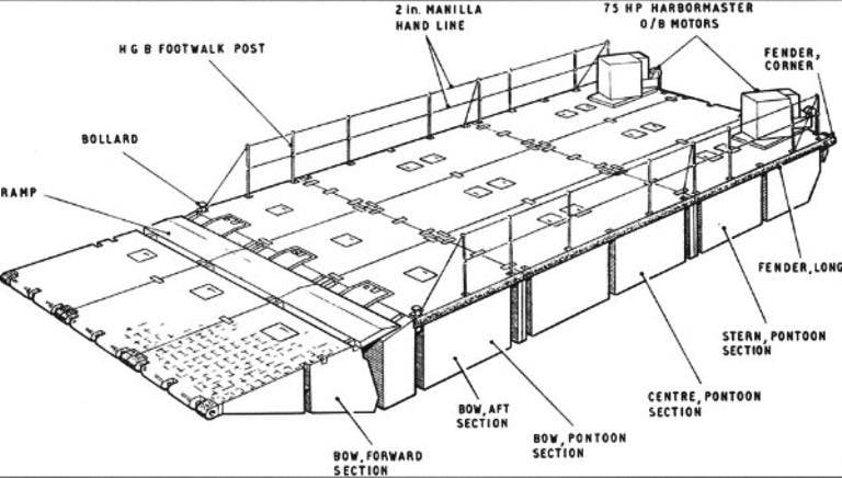
Each version consists of three components: bow, stern and centre, which can be connected together as required, making the Mexeflote a versatile vessel with a total deck size of 66 ft × 24 ft (20m x 7,3m). Such a raft could carry both a class 60 tank and three three-ton trucks.
A single pontoon float has a length of 6,1 m, a width of 2,5 m, and a height of 1,5 m.
The float draft (light) is 30 cm.
The carrying capacity of the float is 10 tons with its own weight of 5 tons.
Various connection versions allow it to be used as a raft, a floating pontoon or as a bridge from ship to shore. However, the 66' x 24' raft can also act as a class 60 single-span bridge."
1. Standard size. Length - 20,12 m, width - 7,32 m, load capacity - 60 tons.
2. Larger versions of Maxi-Mexeflote.
First: length - 38,41 m, width - 7,32 m, carrying capacity - 120 tons.
Second: length - 38,41 m, width - 12,2 m, carrying capacity - 180 tons.
Each version consists of three components: bow, stern and centre, which can be connected together as required, making the Mexeflote a versatile vessel with a total deck size of 66 ft × 24 ft (20m x 7,3m). Such a raft could carry both a class 60 tank and three three-ton trucks.
A single pontoon float has a length of 6,1 m, a width of 2,5 m, and a height of 1,5 m.
The float draft (light) is 30 cm.
The carrying capacity of the float is 10 tons with its own weight of 5 tons.
Various connection versions allow it to be used as a raft, a floating pontoon or as a bridge from ship to shore. However, the 66' x 24' raft can also act as a class 60 single-span bridge."
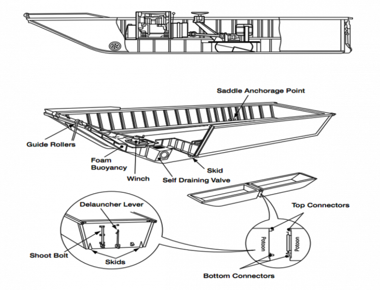
View of the main sections of the pontoon. Clearly visible grooves for inserting connections
The required operating conditions for the equipment were harsh: the pontoons had to be able to connect to rafts or dikes on two-foot waves, and operate on waves of 4 to 5 feet (1,2–1,5 m). In addition, the equipment had to keep the empty vessel moored in waves from 9 to 10 feet (2,7 - 3 m), and when towing the vessel and in waves up to 12 feet (3,6 m).
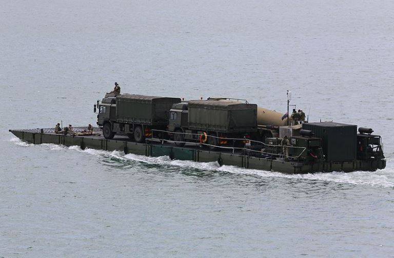
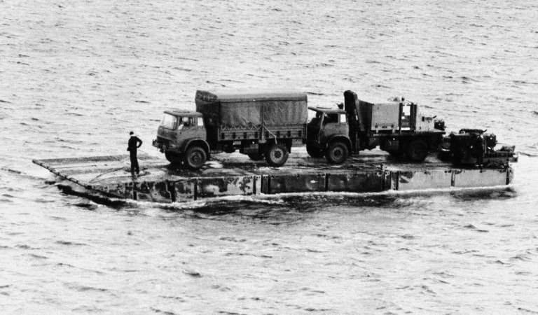
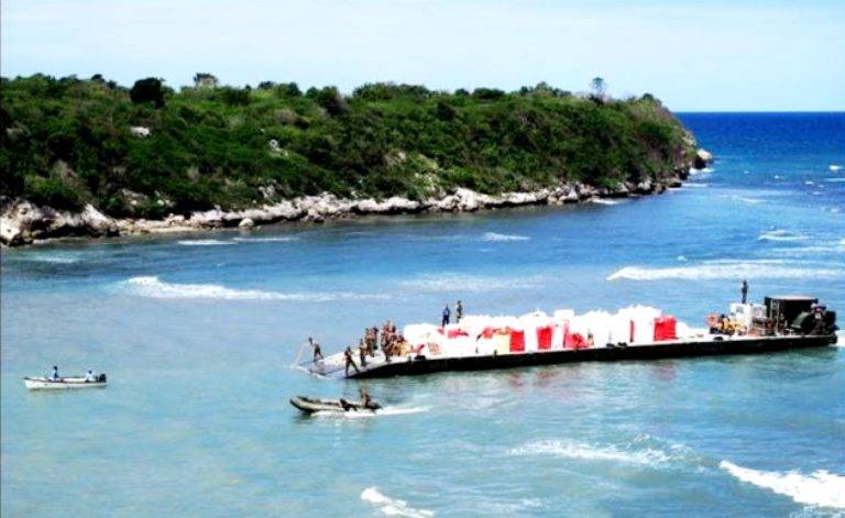
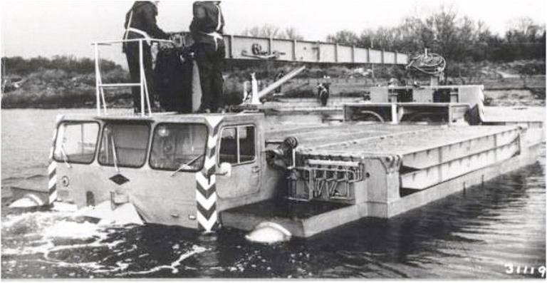
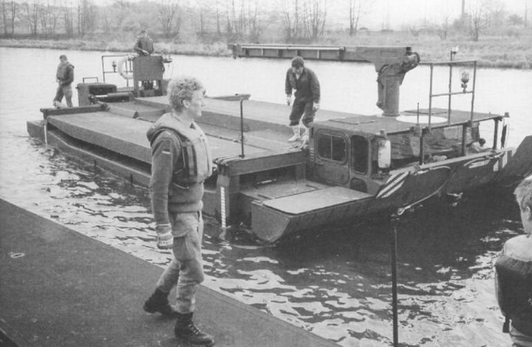
Mexeflote operating as a ship-to-shore power ferry
The first set of Mexeflote entered service with the British Army in 1965.
Elegant in its simplicity, it is simply sections of a pontoon that can be joined together (like a bailey bridge) to form lightweight rafts, jetties and piers.
When used as a motor pontoon, it uses large outboard motors.
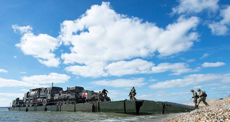
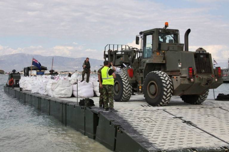
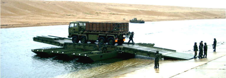
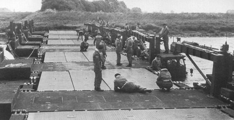
Unloading wheeled and tracked vehicles from the ferry to the bridgehead
Several Mexeflotes can be combined and, in addition to acting as a motorized raft, can act as a jetty, floating transition platform or other floating structures. Modular design allows you to create a variety of shapes.
When pontoons are used as a motor ferry (raft), its crew usually consists of 6 people, led by a junior non-commissioned officer.
Individual pontoons are welded steel construction with smooth sides. On the sides and ends of the pontoons, grooves are built into which connectors are inserted.
The bow pontoon consists of a front part, aft part and a ramp. The forward section is hinged to the bottom edge of the box-shaped aft section and can be pivoted vertically up to a maximum of 457mm above deck level and down a maximum of 380mm below the aft surface.
The removable, manually operated articulator is mounted in a recess in the rear and connected to the front by a hydraulic cylinder. The articulator has a safe working load of more than 80 tons.
The pontoon ramp is pivotally connected to the front part and slides along the forward end of the aft part, closing the gap between the sections.
The central pontoon is a box-shaped block with an internal side bulkhead dividing the interior into two watertight compartments.
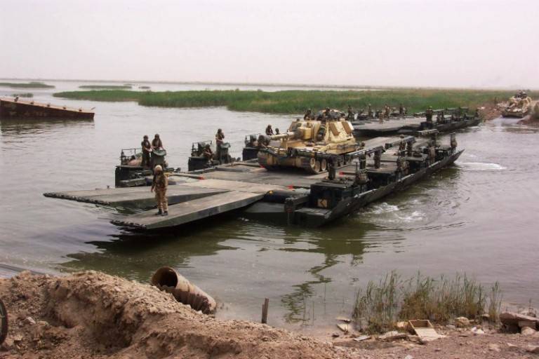
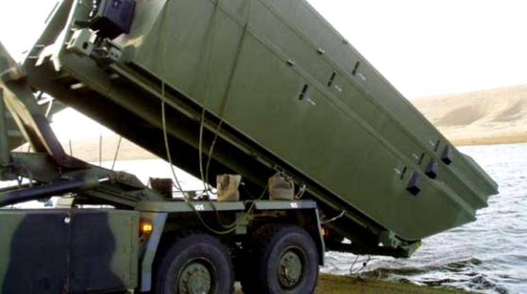
Class 60 motorized lightweight raft built by Mexeflotes
General view of the bow pontoon with the engine
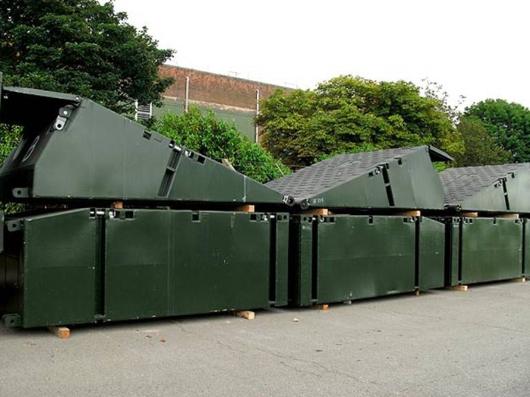
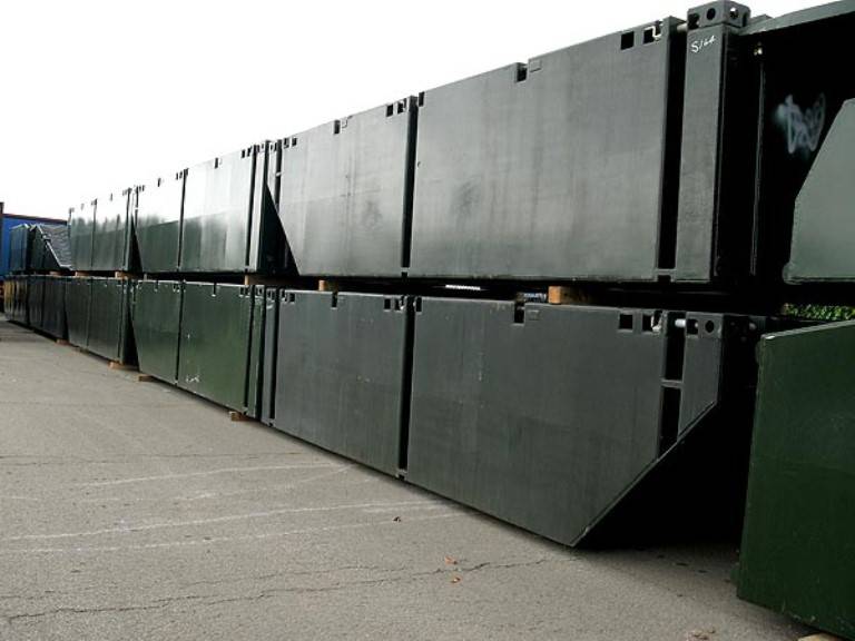
Mexeflotes pontoons, folded to be sent to the troops. On the second tier, you can clearly see the ramps of the bow pontoons
Motor ferry Mexeflotes in operation
Sykes Hydromaster Modular Z Drive Powerplants with 75 hp. With. provide driving force when using the pontoon as a motorized raft, moving it at a speed of about 5 knots. And while it may not look particularly seaworthy, they can be used in 1,5m seas.
This raft is transported, as a rule, in pairs (2 pieces) along the sides of landing ships. The size of the transported rafts is 38,3 by 7,3 m. This size of the raft is formed by adding nine more central pontoons to the standard class 60 raft.
Falklands war
Mexeflotes performed at its best in 1982 during the extremely difficult logistical operation to liberate the Falklands, codenamed "Corporate". The supply lines stretched for 8 miles or 000 days of sailing from Great Britain, and there were no previous plans for an operation of this magnitude outside of Europe.
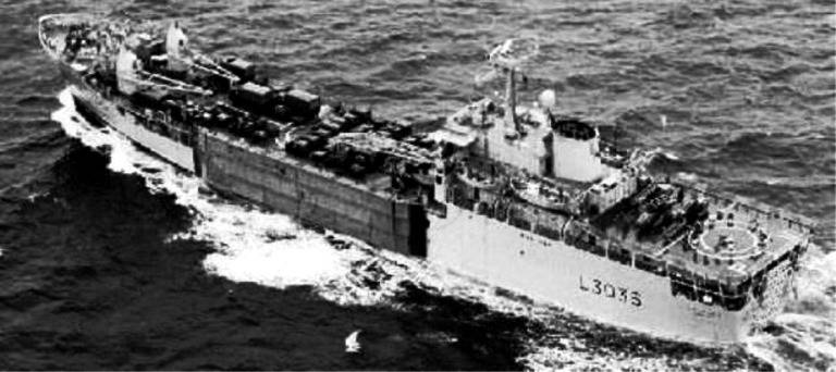
Each of the Knights-class landing craft sent to the islands had one or two Mexeflote, which were attached to the sides of the ship.
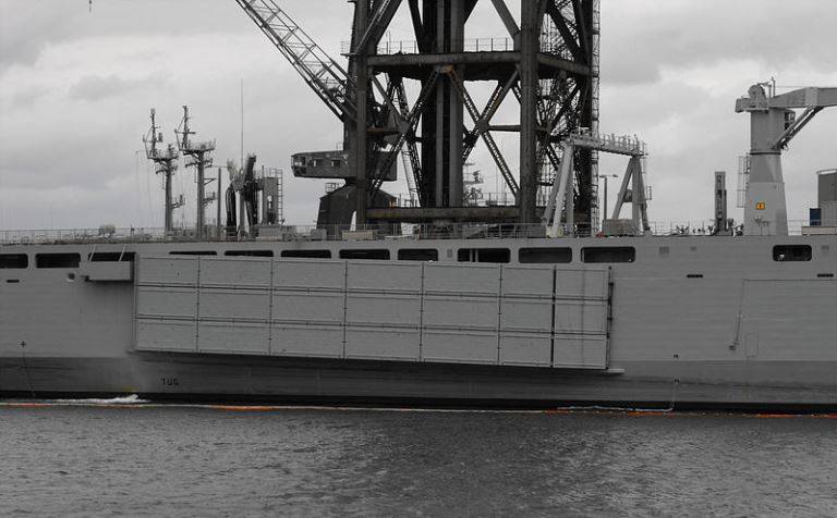
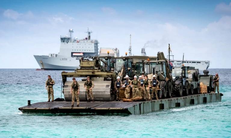
Mexeflote suspended from the starboard side of HMAS Choules
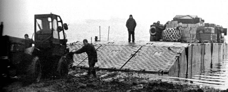
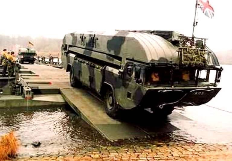
Mexeflote gets to war
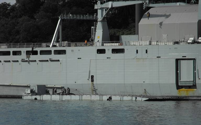
Ferry in war zone
Operating at San Carlos Water and using Mexeflotes, the British landed a significant number of vehicles and depots, including the 63rd RAF Battery Regiment. It is estimated that Mexeflotes unloaded about 75% of their stores, and due to the weight they carried, especially the ammunition pallets, the pontoons were often under water, as shown in the photo below.
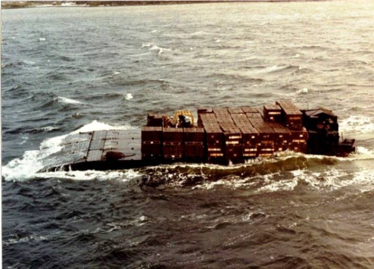
Mexeflote transports pallets of ammunition
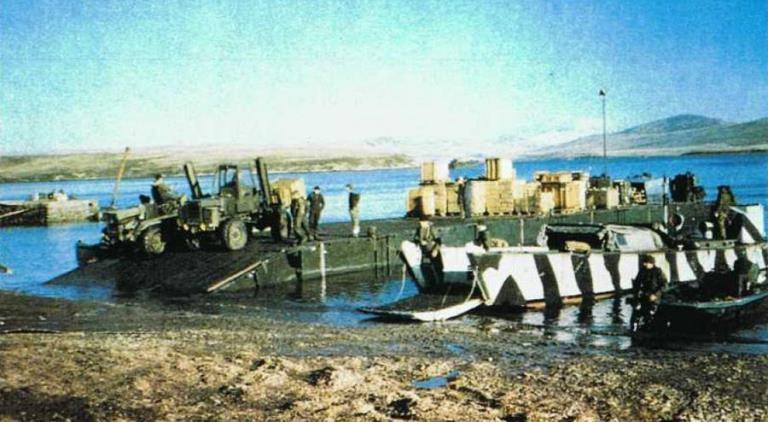
Mexeflote offloading men and ammunition in the San Carlos area
Landing craft were used to transfer equipment from larger RORO ships and it was during this operation that Mexeflote was used as ship-to-ship dams on the open ocean and cargo was transferred between ships over the Mexeflote bridge using Fiat Allis forklifts. Under sea conditions, this must have been a very difficult operation.
During this operation, Sergeant Derrick Sidney Boltby of the 17th RCT Harbor Regiment (where the pontoon was operated) was awarded a military medal for using his Mexeflote to rescue survivors at Bluff Cove.
Here's what it says on wiki2.org:
“Sergeant Boltby of the 17th Port Regiment RCT was the non-commissioned officer in charge of the Mexeflote rafts throughout the operation in the Falkland Islands. On Ascension Island, during a massive transshipment operation, he worked around the clock in difficult conditions to quickly move the cargo. At San Carlos Water, Mexeflote rafts were instrumental in unloading equipment to ensure the success of the fighting. From the open position offered by such a raft, Sergeant Boltby worked continuously during the daytime and in extreme weather conditions.
The vulnerability of his position to constant enemy air attacks did not prevent him from completing this task, and he was an inspiration to his team and other RCT personnel. He was the helmsman of the Mexeflote, was present at Fitzroy during the bombing of RFA SIR GALAHAD and RFA SIR TRISTRAM, and repeatedly returned to the wrecked area to rescue survivors, and, completely ignoring his safety, dived into the sea to rescue a Chinese crew member. Sergeant Boltby's dedication to his tasks in dangerous conditions was outstanding."
The vulnerability of his position to constant enemy air attacks did not prevent him from completing this task, and he was an inspiration to his team and other RCT personnel. He was the helmsman of the Mexeflote, was present at Fitzroy during the bombing of RFA SIR GALAHAD and RFA SIR TRISTRAM, and repeatedly returned to the wrecked area to rescue survivors, and, completely ignoring his safety, dived into the sea to rescue a Chinese crew member. Sergeant Boltby's dedication to his tasks in dangerous conditions was outstanding."
During the operation, drawing attention to the lack of transferring fuel from ship to shore, Mexeflote was used to move vehicles with fuel in containers. They were taken ashore, used to fill canisters, and returned to the ship for refueling. It was hardly effective, but it was the best that was available.
Transfer of property and equipment from ship to shore
After the end of hostilities, Mexeflotes continued to provide ship-to-shore transfer services until more permanent offloading facilities such as FIPASS could be established.
The rafts are currently manned by the Royal Logistic Corps and are primarily used by Royal Auxiliary Bay-class landing craft. fleet.
As part of the Royal Australian Navy's acquisition of the Bay-class ship RFA Largs Bay (renamed HMAS Choules for Australian service), two Mexeflotes were also acquired.
Canadian military ferries on Mexeflotes
Haiti
In the aftermath of the earthquake in Haiti, a Royal Navy Bay-class support ship carrying members of the 17th Marine Regiment of the Royal Logistic Corps and other parts of the armed forces delivered much-needed food and other supplies to the Haitian capital of Port-au-Prince. The ship and its crew continued to operate for some time, redistributing food and World Food Program (WFP) supplies to Haitian communities that had been cut off from the rest of the island by the earthquake.
After the disaster, the population of Anse-à-Vaux in the province of Nippes in southern Haiti increased with refugees from Port-au-Prince. Since the roads were impassable due to mudslides and floods, airlifts were the only way to get aid to the area. But that wasn't enough.
WFP has tasked RFA Largs Bay and its team with delivering the first major relief package to Anse-à-Vaux after the earthquake by sea.
During a four-day relief operation, the Mexeflote RFA Largs Bay raft transported 275 cooked meals, 000 tons of rice, 30 tons of beans, over 6 crates of corn-soy mix, over 200 crates of cooking oil and 100 bags of salt ashore at Anse-a -In.
Mexeflote delivers humanitarian cargo to Haiti
Class 16 portable air bridge
With the development of the British airborne forces, it became a natural requirement to support them with appropriate bridging facilities. This was reinforced by the creation of a strategic reserve of Great Britain and a general change in the situation in the world, when Great Britain withdrew its forces back to the island in the late sixties of the twentieth century.
The result of work in this direction was the Air Portable Bridge (APB / APFB) or air portable ferry bridge.
The requirements for the Class 16 air portable bridge were stringent. These included: that it be naturally airborne and adaptable for use as a ferry, floating bridge, and 50-foot (15 m) dry-gap bridge. .).
The requirements for an air transportable (in English terminology - airport or APFB) class 16 bridge, developed in the early 1960s, were a direct result of the decision to create a strategic reserve in the UK, which was mentioned earlier. It was necessary to create a bridge for sappers, which would be compact, lightweight and, above all, easily portable, for use in the initial stage of air transport in limited or cold war operations.
The equipment had to be adapted as either a crossing (primary function), a floating bridge, or a 50 ft (15,2 m) "dry span" bridge. The design team that worked on the bridge was led by Colonel Weld, who had previously served in MEXE as a project leader with the rank of major.
In May 1962, MEXE put forward a proposal to design a bridge built in light alloy boxes. The boxes and ramps had to be internally rigid so that when joined together they would form the main beams and transoms of the bridge. Then the top of the boxes will be a bridge platform.
The connection was assumed to be by means of dovetail or interlocking fasteners along the lower surfaces and by means of tensile and shear connectors on the upper faces.
For the pontoon version of the bridge, the boxes themselves had to provide most of the necessary buoyancy, with pneumatic floats attached to the short ends of each box providing additional buoyancy. In the process of work, I had to study a number of previously unexplored aspects in this design.
First of all, the behavior of a floating bridge in a fast current, when the bridge was actually one continuous pontoon. It has been considered that increasing the design spaces between individual pontoons, even at the smallest dimensions, can cause problems with floating debris and can also cause stability problems in shallow rivers.
In view of these uncertainties, it was nevertheless decided to continue work on a new design.
At the same time, a more conventional design had to be created in parallel to provide a fallback option if required, as well as provide an opportunity for comparison, including cost and expected performance.
The firm of consulting engineers Posford, Pavry and Partners was chosen to develop the more orthodox design of the APB. In short: their design consisted of 4,25m panels with male connections at each end and fastened together with female pins, and the transoms had to be spaced 2m apart, supporting the 4,25m deck panels.
The floating and raft versions of the bridge were to be supported on 42-foot (12,7 m) piers formed from fairly conventional 21-foot pontoons. The pontoons were to be partially decked to allow the bridge and deck panels to be placed inside the cargo bays of road and air transport.
As a result, the development and production costs of the new bridge of the MEXE version turned out to be lower than that of the Posford, Pavry and Partners version, and this influenced the final decision to adopt the bridge from the MEXE.
In its final form, the Air Portable Bridge did not differ much from the original MEXE proposals.
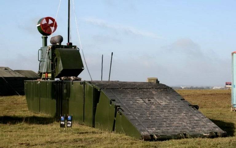
The APFB is based on the very successful Medium Girder Bridge (MGB) and the two systems share many common parts. By incorporating a relatively small number of new components, the APFB expands the capabilities of the MGB system to meet the changing needs of the military. APFBs can be quickly deployed and engaged by forward forces or disaster relief teams in a wide range of operational and climatic conditions.
One set of APFB, including 7 pontoons, can block a water barrier up to 15 m wide.
The APFB can be configured to be transported using its own trailers, on DROPS platforms, or in standard ISO containers. It can be transported in the transport compartment of a C-130 Hercules aircraft or a Chinook helicopter as a suspended load. The bridge can also be parachute-dropped on Medium Load Platforms (MSPs). The APFB can also be transported by standard cars, trucks and SUVs, both military and civilian.
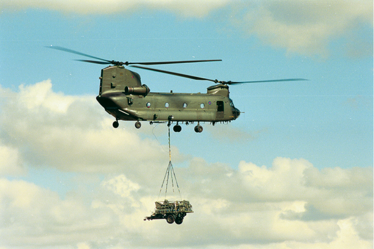
Helicopter transfer of APFB components
The bridge consisted of a series of light alloy boxes, each measuring 12 feet × 4 feet × 15 inches (3,65 x 4,56 x 0,38 m) and weighing about 600 pounds (270 kg), seven of which could be joined together along the long sides, to form with 3,5m tapered ramp sections a 50ft bridge.
The top of the boxes formed the deck of the bridge, making it possible to obtain a roadway with a width of 3,34 m.
Here is how J. Chester describes the boxes and flooring in his book Military Bridges:
“The prototype boxes were made from aluminum sheet welded together, more like a large egg crate, but this construction proved to be too heavy and the welded sheet tended to flake and corrode. Therefore, the design was modified to use a welded trellis frame to which the outer skins were riveted and bolted. Various forms of construction were considered for the 1½" deep box deck to withstand local bending loads as well as the overall compressive bending load on the bridge. An alloy honeycomb-filled light alloy sandwich similar to that used for the wings of the latest RAF V bombers was considered. However, the final version used aluminum alloy profiles welded together along the axle of the bridge. The ramps were similar in construction to the boxes, with extensive use of the newly developed aluminium-zinc-magnesium weldable alloy.”
For the floating versions of the bridge, pneumatic floats have been added at each end of the boxes to provide additional buoyancy as well as improve the water profile. The floats were made of neoprene nylon fabric, consisting of three tubes that were connected together but were not individually breathable.
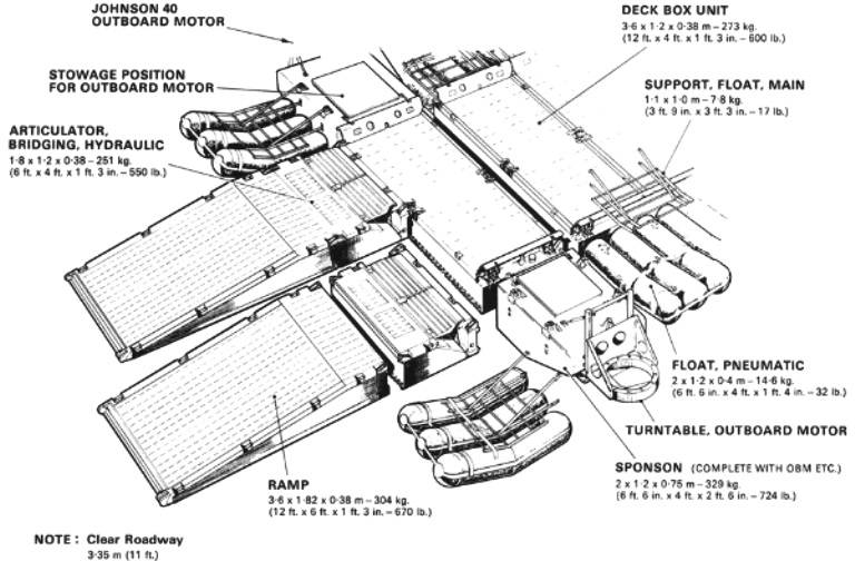
Air Portable Bridge Components
Thus, each float had a single inflation point and could be inflated by connecting to the Land Rover exhaust system using Aqualung air tanks or a compressor, or (to increase the working pressure of 1,08 kg per square inch) using a small manual inflation pump.
To counteract the upward movement of the float, a support frame was installed above each of them, connected to the ends of the main boxes.
At each corner of the raft, the pneumatic floats were replaced by a small light alloy pontoon that supported a 40hp Johnson outboard motor. With. The engine was mounted on a specially designed turntable, which was also used as a storage container for shipping.
Articulator assemblies were installed at each end of the floating bridge or raft between the end box and the ramp sections to allow the ramps to be raised and lowered and adjusted as the river level changed.
The bridge was a class 16 unrestricted bridge, but in a floating version it could (with a speed limit and with additional buoyancy provided by the addition of two additional boxes and floats) carry a class 20 medium wheeled tractor and other class 17/19 specified loads. On the wfel.com website, for a raft from this kit, even a load of class 35 is indicated.
APFB equipment is transported on five special trailers towed by Land Rover.
Technical testing of the new equipment was followed by field trials conducted during 1967 in the UK and Australia. An interesting test involved the installation of a carriage and the installation of a complete 50-foot bridge on it, which was transported by helicopter. At the beginning of the tests, the slings were attached to the end boxes of the bridge rather than the ends of the ramps. The ensuing vibration caused a severe fatigue acceleration of the top ramp connectors, and as a result one of the ramps fell over Sussex.
A few years later, during the Falklands Campaign, a 42-foot (12 m) bridge over the Murrell River, capable of supporting an APC, was successfully installed by this method using a Chinook helicopter.
The first production bridge kits manufactured by Laird Ltd. were given to the British and Australian Army in 1970. At the same time, the British army received 16 APFB sets.
The set of bridges consisted of enough equipment to form four rafts, each with a clear deck length of 12,15 m, a 58,3 m floating bridge or four 15 m dry bridges.
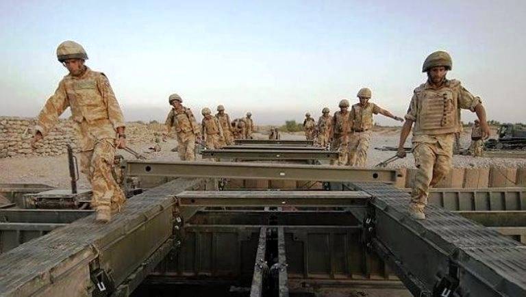
It should be noted that the APFB equipment proved to be easy to use and quick to assemble. So, a unit of 20 people spent no more than 16 minutes on the construction of a self-propelled 40-meter ferry.
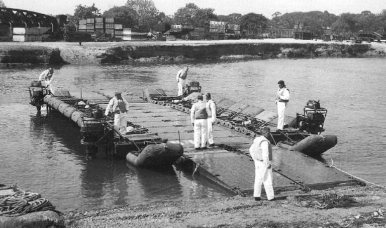
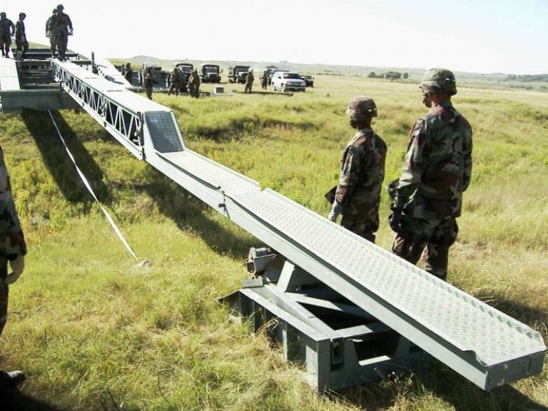
Part of the APFB bridge in testing
APFB ferry
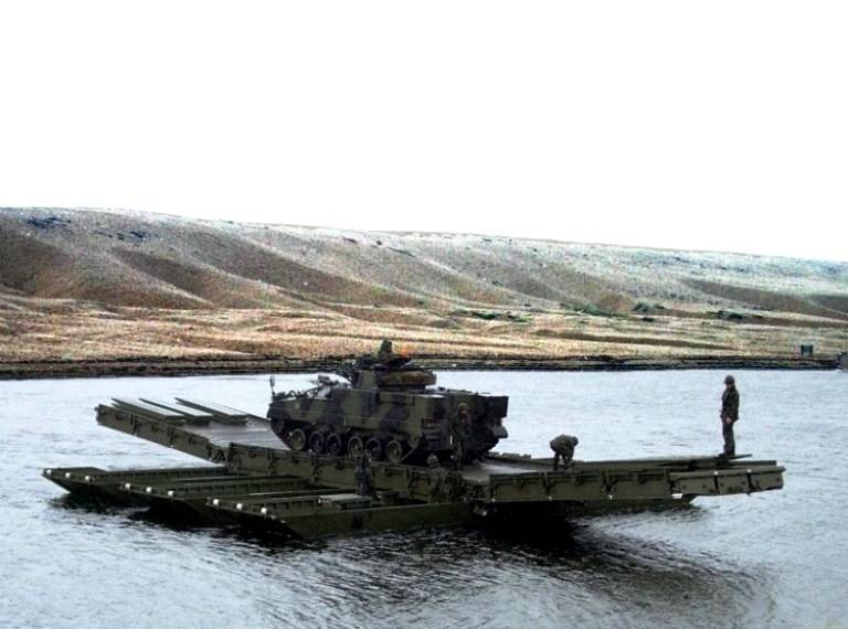
The APFB ferry is the main configuration of the APFB bridge for crossing water barriers. It is a free-floating ferry with class 35 capacity for tracked and wheeled vehicles. This is a modular bridge with hinged platforms, mounted on six pontoons. The bridge structure is fixed on the pontoons with six supporting hooks.
Each pontoon includes a self-closing system to allow any water inside the pontoon to drain automatically. The hydraulic system used to raise and lower the landing pads is powered by diesel engines on the pontoons.
Two pontoons are equipped with diesel power plants, which makes her very maneuverable and accelerates to a speed of 6 knots.
The ferry team consists of 16 people, including 2 non-commissioned officers.
Air portable bridge APFB in the configuration of the ferry, assembled from the "dry" span ARV installed on pontoons
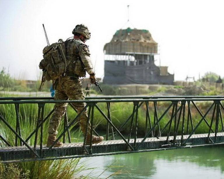
APFB has been successfully used in Afghanistan, providing the advancement of troops, but mainly to restore infrastructure in a particular province.
Here is what it says on the website of the Royal Engineers of the British Army:
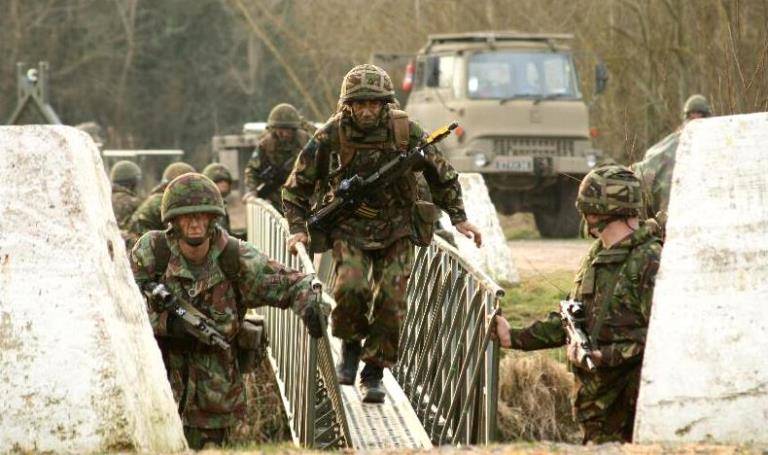
“A bridge rumbled over the first pontoon. A total of 3 pontoons were used to build the ferry bridge. Members of the 3rd Parachute Combat Team, which included troops from the 3rd Parachute Regiment Battalion, 51st Airborne Squadron Royal Engineers, the Royal Irish Regiment and D Cavalry Squadron, took part in Operation Bugs.
The operation took place in the city of Sangin in the northern province of Helmand. During the mission, 51 Para Sqn RE troops were the first to complete engineering work by building an aerial portable ferry bridge across the Helmand River.
The construction of the bridge took about 7 hours. The troops arrived in Sangin at dawn and cleared a safe path to the district center to ensure resupply and transfer of vehicles to Sangin. A task force was set up to carry out the operation in Helmand province, and an intergovernmental provincial reconstruction team was established in Lashkargar to help the Afghan government build strong government institutions, provide security and create jobs.”
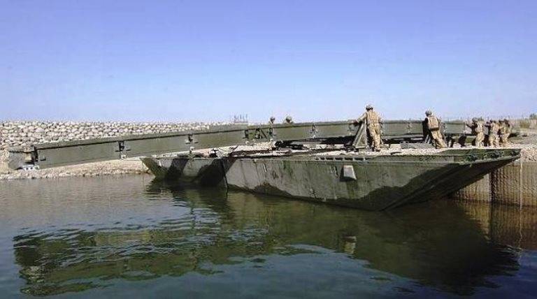
Aerial portable ferry bridge in Afghanistan, Helmand province
20ft inflatable bridge
While the airport bridge was being developed, the idea of an inflatable bridge for similar use in airborne operations and expeditions was seriously considered.
Structures made by inflating flexible fabric tubes or plates have obvious advantages when low volume and light weight are more important than durability or strength. Good examples are reconnaissance boats used by sappers and inflatable lifeboats.
However, a clear span bridge is a more complex structure. In the mid-1960s, it was decided to study the practical difficulties by designing and building an experimental bridge, which was made in East Cowes by British Hovercraft. To save time, existing rather than custom-designed fabrics were used instead of a feasibility study, and the bridge deck was simply sheathed with wooden planks.
Thus, the bridge was made of three-layer boat deck fabric, the upper load-bearing surface of which consisted of wooden battens capable of absorbing the compressive loads of the bridge, and flexible steel wires were attached to the lower surface to withstand longitudinal tension. The bridge was 20 feet (6,08 m) long, excluding 8-foot (2,43 m) inflatable ramps, and 9 feet (2,73 m) wide, giving an 8-foot wide roadway.
Longitudinal and transverse internal diaphragms maintained a deflection of up to 60 cm at mid-span at a filling pressure of 0,9 kg per square inch. In testing, the bridge, which could be stowed as a backpack 2,43 m long, 60 cm in diameter and weighing about 700 pounds (315 kg), was successfully transported by a long-wheelbase Land Rover.
This product could be used both as a "dry" bridge and as a raft.
However, for a number of reasons, this idea was not developed, although in fact what could be considered a disadvantage, namely the ability to quickly deflate when firing from small arms weapons, it was not. The bullets left only tiny holes in the body, which led to a very slow exit of air.
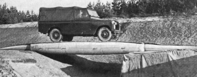
20ft Experimental Clear Span Inflatable Bridge
With the advent of the Bailey Bridge, a real revolution took place in the world of military bridges.
To repeat this within the framework of the English army for the second time would be simply amazing and amazing.
But MEXE was able to do this with Medium Girder Bridge (MGB).
Design work on the MGB began in the early sixties in response to a need for a "hand built" bridge that could carry a Class 60 (up to 63,5 t) load on a 100-foot (30 m) span and be used on battle group supply routes. , not falling into the zone of direct fire.
MGB's design project leader was former Royal Engineers Major Eric Longbott, who helped design the Mobile Bailey, Heavy Girder Bridge and even the Mexeflote.
The developed bridge is used in two versions.
The first is like a bridge for covering obstacles on land.
The second is like a pontoon bridge.
Medium girder bridge (MGB) components launching the nose of the "land" variant
Pontoon Bridge MGB
To overcome water obstacles, the MGB may provide for the creation of a class 70 pontoon bridge.
It can be used in a single or double deck configuration depending on the distance between the pontoons.
Where a large rise and fall of the river level is expected due to flooding or tides, the two-story design allows the landing span to be extended (up to 24 m) and thus take into account this change. Also, a two-story floating bridge can take banks up to 5 meters high.
The one-story design provides for the creation of either pontoon bridges or ferries for load classes MLC 60.
Pontoon MGBs in single or double deck configurations are built using the same components as dry bridge configurations, carried over to MGB pontoons with single deck hinged bays or double deck bay connectors to provide articulation. The length of these bridges is only limited by the amount of equipment available.
This bridge remains in operation today.
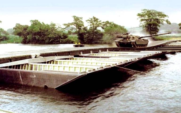
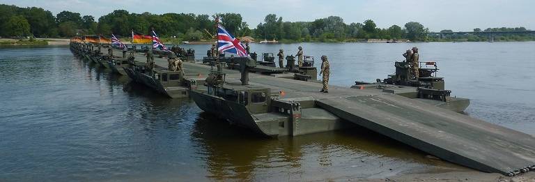
Single deck pontoon bridge MGB
Multi-span pontoon bridge with two-story configuration MGB. In comparison with the photo above, the greater distance between the pontoons is clearly noticeable and the fact that this bridge is installed between elevated banks
The pontoons used in the MGB bridges are made from marine-grade aluminum alloy.
Two pontoons are connected back to back, forming each pontoon pier. Three such berths make up one raft of the berth (see photo above). Fully loaded pontoons can work with river flow up to 2,5 m/s.
MGB pontoons can also be used to build class 90 floating ferries.
Self-propelled ferries are driven by a water jet power plant and a 75 hp diesel engine. With.
Medium girder bridge pontoon (MGB), design and assembly scheme
Compact pontoons Mabey
The Mabey Universal Bridge, introduced in 1976, is a powerful member of the Mabey bridge family and is used all over the world, especially in the most demanding areas of the US and Europe.
In the floating version, Mabey compact pontoons have side and end panels, bulkheads and frames. The panels and frames of the pontoon are quickly bolted together with a Mabey tool to ensure precise assembly, and then the top and bottom skin plates are welded on to complete the structure.
The basic Mabey Uniflote center pontoon is 5,8m long, 2,43m wide and 1,28m high, with the bow pontoon slightly longer.
The pontoons can be assembled into pontoon supports using two to five units (for floating bridge applications), or can be assembled into a range of ferries with a load capacity of up to 107 tons.
The Mabey Uniflote, formerly the Thos Storey Uniflote, is similar in many respects to the Mexeflote we reviewed previously, and limited purchases of equipment were made for military use prior to the production of the Mexeflote.
Indeed, after their introduction in 1956, Uniflotes were used in Floating HGB trials in the late 1950s. The equipment is a block-constructive floating system, consisting of identical floating craft, which can be assembled into rafts of different carrying capacity. The rafts can then be used for a variety of purposes, such as carrying heavy loads across the water, as a support system for a pontoon bridge, as a ferry or wharf.
The standard device is a steel-framed pontoon with a square end, 8 feet wide, 4 feet high, and 17 feet 4 inches long (2,43 x 1,21 x 5,27 m respectively).
Also available are 12-foot (3,65 m) and 18-foot (5,47 m) ramps and 6-foot terminations, as well as a 6-foot (1,82 m) Uniflote version.
All units are equipped with connectors at the sides and ends so that Uniflotes can be joined together in the water from deck level. Connectors allow full transfer of transverse and bending loads between blocks on the raft. Various accessories are available such as Uniflotes spacing connectors and supports for bridge beams or winches.
Launch of the Mabey Compact 200 bridge to create a floating bridge with Uniflote pontoons at Xi-Xai in Mozambique
Another photo of the Mabey Compact 200 bridge
Williams Fairey Engineering Ltd
A significant number of MGB medium girder bridges have been manufactured by Fairey Engineering.
But in 1986, this enterprise was taken over by Williams Holdings and became Williams Fairey Engineering Ltd, which still operates in Stockport.
MGB production continued, albeit on a smaller scale, and the firm itself remains active in the development of the military bridge to this day. Its latest innovation is the Axial Folding Bridge (AFB), the brainchild of Stuart Parramore.
The AFB Axle Folding Bridge was originally designed to meet the US Navy's requirements for a lightweight bridge that could be used in conjunction with their USN seawall system and to offload RORO ships.
The bridge consists of 5,83m x 4,04m lightweight, high-strength aluminum sections that fold into compact modules, two of which can be palletized and handled like a standard ISO container load. Tapered sections of the ramp of the same length are hinged in such a way that they can be lifted up, forming a bridge with a flat deck.
A reinforcement kit is also available to extend the span of the bridge, which is capable of spanning gaps from 17m on the MLC 70 (using three modules) to 47m on the MLC 60 (using eight modules).
The construction time for the 41 m long bridge was less than an hour with the help of a team of eight people.
A modified version of this bridge is now officially accepted in the US as the MLC 100 Heavy Dry Support Bridge.
The mid-beam bridge pontoon, the MVEE concept developed by Fairey Engineering, also continues.
Loading nested Williams Fairey Engineering MGB pontoons onto an Ampliroll truck
Although this pontoon was not purchased by the British Army due to sufficient stocks of M2 and M3 equipment, it proved to be quite successful and was acquired by a number of overseas armies.
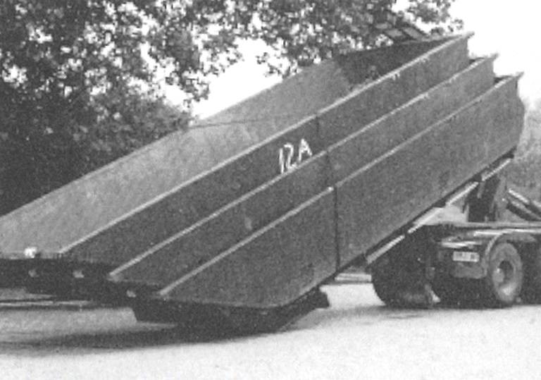
The open top pontoon can be nested inside one another for easy storage and transportation. Four of these pontoons are transported on an Ampliroll truck or on a special trailer. At the same time, in both cases, the loading platform is able to tip over so that each pontoon can be launched individually.
The pontoon is made of NS8 marine aluminum alloy. Its length is 7,9 m, width - 2,6 m, height - 1,16 m, weight - 1 kg, and buoyancy - about 080 tons. Two pontoons connected end-to-end form the bridge's support.
Launching Williams Fairey pontoons
Williams Fairey Engineering's latest contribution to military bridges was the development of the new Air Portable Ferry Bridge to replace the Air Portable in the 1970s.
The new bridge will be an MLC 35 system based on an upgraded version of the MGB and will be transported by C130 aircraft. The system will provide a light bridge with a span of up to 28 m and a motor ferry with a deck of up to 14 m.
Bridge amphibians
The service of the Gillois amphibian, adopted in 1961 by the engineering troops, was short-lived.
It was soon replaced by a German alternative, the M2 self-propelled ferry.
The M2 was developed under contract with the German federal authorities by a consortium of Klockner-Humboldt-Deutz (KHD) and Eisenwerke Kaiserslautern (EWK), with EWK being the same firm that produced Gillois.
The Ministry of Defense decided to purchase German bridge and crossing equipment in much larger volumes than Gillois.
At the request of the UK, the Germans conducted comprehensive loading tests tank Centurion with a bridge at the German Federal Proving Ground at Koblenz and then further sea trials were carried out in the spring of 1962.
By June 1962 it was clear that the M2 was noticeably superior to the EWK/Gillois in almost every way.
The M2 has greater mobility on soft ground, short time required to open the side pontoons, immediate controllable thrust after entering the water, higher water speeds, protection of propellers from external damage, wider roadway.
Also, the German car had greater versatility for collecting ferries of different carrying capacities, increased safety due to a larger number of sealed hull compartments.
When organizing the crossing, fewer amphibians were required to build a bridge of the same length as the Gillois.
On the other hand, ramp reach and height range were not as good as the Gillois.
Therefore, it was decided at first to leave both machines in operation. In the future, it was proposed to purchase only M2, taking into account the various modifications proposed during the tests.
It is interesting to note that the US Army also decided not to continue purchasing Gillois and continued to produce its own amphibious version.
One M2 provided by the German Army arrived in the UK in August 1962, and after limited sea and ferry testing on the MEXE, which was mainly about comparing its performance to that of the Gillois, the ferry was sent for vehicle testing.
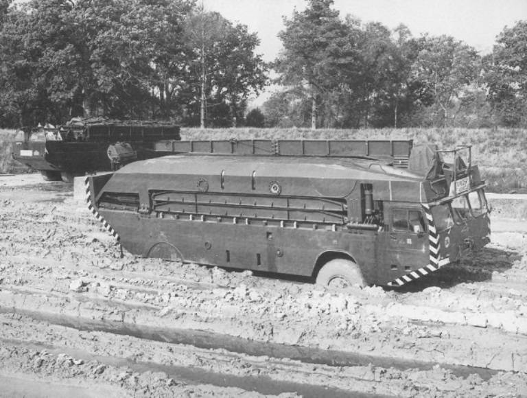
Swamping tests of the M2 amphibian at Khurn, near Christchurch. The Gillois ferry-bridge machine is visible in the background.
The M2 was an amphibious aircraft with class 24 buoyancy, decking and ramps needed to build a bridge or ferry. The folded side pontoons were located above the body of the machine and were hydraulically brought into position before entering the water.
Four bridge/ramp stringers were placed upside down while traveling on the road, two under each retracted side pontoon. They were attached to the side pontoons and thus rotated with them when the pontoons were extended.
The stringers were then swiveled into position using an assembly gantry crane at the front end of the vehicle. They were used as hydraulically operated landing ramps at the end of a bridge or crossing, or to create a span between adjacent pontoons.
The crew of the car - 4 people (driver, pilot, crane operator and sailor), length - more than 11 m, weight - 22 tons. Two engines with a capacity of 175 liters. With. provided sufficient power for movement on land and for movement on water at a speed of 60 and 12 km / h, respectively.
It is noteworthy that only one engine is used on land, but in the water one engine drives the central steerable propeller, and the other two reversible side propellers.
One M2 can be operated as a class 10 ferry (up to 12,6t) and two machines connected together form a class 30 ferry (up to 32t). The length of the bridge from one set of M2 is 100 m, the maximum carrying capacity of such a bridge reaches class 60 (up to 56,3 tons for tracked vehicles and up to 63 tons for wheeled vehicles). Throughput - up to 400 cars per hour.
Further modifications of the ferry made it possible to increase the carrying capacity to MLC 70 (up to 62 tons) for tracked vehicles and MLC 93 (up to 90 tons) for wheeled vehicles.
M2 Rig during testing
The first production vehicles began to enter service with the Royal Engineers only in 1969. These were already modernized M2B amphibians.
It should be noted here that training to work with new equipment was started back in 1964.
With the firm decision to procure the M2, it became apparent that a new specialized regiment would need to be formed to deal with such specialized equipment. They became the 28th Airborne Engineer Regiment, which was formed in 1970 in the West German city of Hameln on the Weser River. Lieutenant Colonel J. Goodson was appointed commander of the regiment. The formation of the unit was completed on April 7, 1971.
The regiment was given the task of ensuring the rapid transfer of all units of the 1st British Corps across the rivers and canals in the area of operations of the corps.
Organizationally, the regiment consisted of three detachments, each detachment had 8 M2V vehicles.
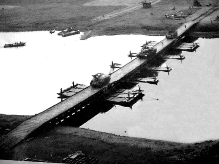
In 1980, the 28th M2 assembled the longest bridge ever built for these vehicles. The length of the bridge over the river The Rhine near the city of Speyer was 476 meters. For this, 54 M2 machines were used.
Training on the Weser River using serial M2B amphibians, Germany, 1980
In the mid-1970s, a new modification appeared - M2D with additional inflatable tanks located on the sides of the car. This made it possible to increase the load capacity of the bridge to class 70, which is necessary to transport the latest Challenger battle tank.
The construction time for a 70-foot (328 m) Class 100 bridge was then one to one and a half hours, while for a Class 70 ferry using three M2D units, it was 30 minutes. On a good stretch, the bridge could handle up to 150 vehicles or up to fifty tanks per hour.
In the mid-1990s, a new version of the amphibian was introduced - the M3 ferry-bridge vehicle.
The requirement of the General Staff No. 3987, put forward in the mid-90s of the twentieth century, as a “Support Bridge” assumed the joint Anglo-German development of a new self-propelled ferry. They became the M3 machine, a further development of the M2 amphibian.
Work on the amphibian began in 1982. The original replacement of the M2 amphibious bridge was scheduled for 1985, but later, due to technical problems, the deadline was postponed to 1986, and then to 1988.
However, the M3 ferry car was adopted by the British army only in 1999. The UK purchased 38 units, each costing £1,2 million.
The amphibious vehicle project was approved in February 1985 and called for the construction of a 70 m long class 120 bridge, preferably in less than 30 minutes, and at night no more than 60 minutes. Also included was a requirement to build a class 70 ferry, preferably in 15 minutes and no more than 30 minutes at night.
The total possible requirement was determined to be 130 vehicles for the West German Army and 70 vehicles for the British Army.
But the end of the Cold War and the subsequent revision of commitments under the Army's "Options for Change" policy dramatically reduced this requirement. In the long-term cost estimate for 1992 for the British army, the figure was reduced to 38 amphibians.
Following a competitive tender in mid-1994, EWK was awarded a contract to manufacture these ferries, with the possibility of entering service after 1998, when the M2 was due to retire.
Ferry M3 during classes, Germany, 2000
In terms of operation, the M3 equipment is far superior to the M2.
In fact, twenty-four people using eight M3s can build a 100-meter amphibious bridge in 20 minutes, while building a similar bridge using 12 M2 amphibious vehicles would take forty-eight people and 45 minutes.
The Amphibious M3 can be used as a ferry or, when multiple vehicles are connected from shore to shore, as a bridge capable of receiving vehicles such as the Challenger 2 main battle tank.
The ferry can deploy pontoons on the move, in or out of the water, no on-site preparation is required to enter the water. Control functions were automated, which reduced the crew from four to three people.
The M3 is only 1,4m longer and 3kg heavier than the M300. At the same time, the car is faster and more maneuverable on land and in water. Four-wheel steering provides a turning circle of 2 meters.
Two water pump nozzles guarantee 360° movement in the water. The M3 operates at water currents of around 3,5 m/s and can maneuver at depths of up to 1,05 m.
The speed of the car in the water is about 9 km/h with a full load and 14 km/h without.
A single M3 can carry a class 70 tracked vehicle where two M2s with additional buoyancy bags would be required for the same task. Also, the M3 received a larger payload for class 100 wheeled vehicles (up to 104,3 tons) and became faster in deployment.
Amphibious M3 and the bridge of these machines on exercises, Germany, 2002
The M3 was first used by the British Waxes in combat in Iraq in March 2003 as part of Operation Telic.
Detachment 412 (V), 23rd Airborne Engineer Squadron, 28th Engineer Regiment, Royal Engineers ferried elements of the 3rd Commando Brigade across the Shatt al-Basra waterway, allowing them to continue their advance on the Iraqi city of Basra.
The next operation was a river crossing at the Rumaila oil fields. Here, M3 amphibious vehicles provided the transfer of three AS90 self-propelled howitzers in support of the 16th Air Assault Brigade of the British Army.
Despite the fact that they were successfully used in the fighting in Iraq, with the last stage of reductions, it was decided to keep the remaining M3 self-propelled ferries on high readiness for use.
Royal Engineers M3 Rigs, Shatt al Arab, Iraq, 2003
Ferry M3, Iraq, 2003

AS90 on the Royal Engineers M3 Ferry. Iraq, 2003
Infantry Assault Bridge IAB
In conclusion, it is necessary to say a few words about the IAB infantry assault bridge, which the British military included in the floating bridge equipment.
It should be noted that it is not always used in "floating mode", but its clear width allows you to overcome not very wide rivers.
The need for such a bridge was justified in 1985 during a study of the possibilities of an infantry assault crossing of the river, conducted by the 1st Corps in Germany. As a result, on a competitive basis, a contract was signed for the design and manufacture of the bridge with the German company EWK, which manufactures the M2 and M3 amphibious bridges.
After testing in the UK and Germany, the bridge was put into service in 1992.
The Infantry Bridge set consists of seven 4,5 m long aluminum modules, a cigar-shaped float and accessories that can be assembled and dismantled from any shore. The float is used to facilitate launching, and it can also be used to increase the distance covered.
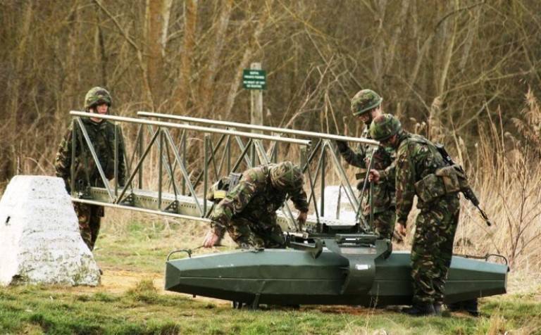
Infantry Assault Bridge
A single-span bridge 16m long can be formed in less than 5 minutes by 8 people, and a single-span bridge 30m long, launched through a water barrier with a float, is built in less than ten minutes. The 44 m bridge can be built using components from two sets of bridges, with two floats acting as an intermediate pier.
The bridge is intended to be used by infantry assault platoons, among whom it is very popular, but is operated by RE support squadrons to facilitate storage, inspection and repair, and to concentrate a limited number of bridges for more efficient use.
A complete axle set is transported on a 4- or 8-ton vehicle. But after unloading, its sections can be carried by the forces of two fighters over distances of up to 600 m or more.
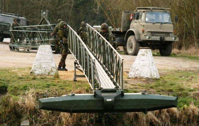
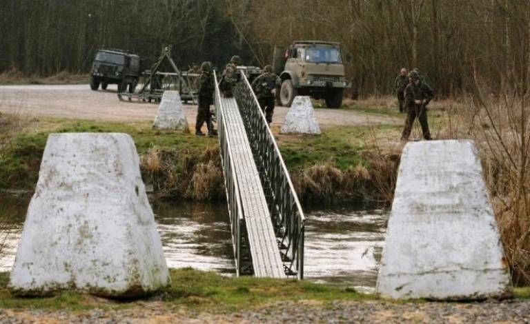
Navigating the IAB bridge over a water barrier and crossing it for an infantry unit
Regardless of the span of the bridge, its maximum load must be limited to three soldiers evenly spaced on the bridge, and the weight of each fighter in full equipment or with the load carried must not exceed 135 kg. The maximum allowable single load is 200 kg, but a set of adapters for a stretcher from the ZIP allows one person to throw a wounded comrade across the bridge without any increased load on the bridge gangway.
IAB has been successfully used in combat operations, for example, in Afghanistan, and is an obvious improvement on the Kapok assault bridge!
Infantry assault bridge in Afghanistan
At the end of our story, we will give a few facts about the use of pontoon equipment by British engineers in Iraq.
Before the hostilities in 1991 in Al-Bushayr across the river. Shatt al-Arab stretched a concrete bridge, the middle part of which was a drawbridge, which made it possible to pass various river transport along the river without delay. The bridge passes over an island in the middle of the river called Sinbad Island.
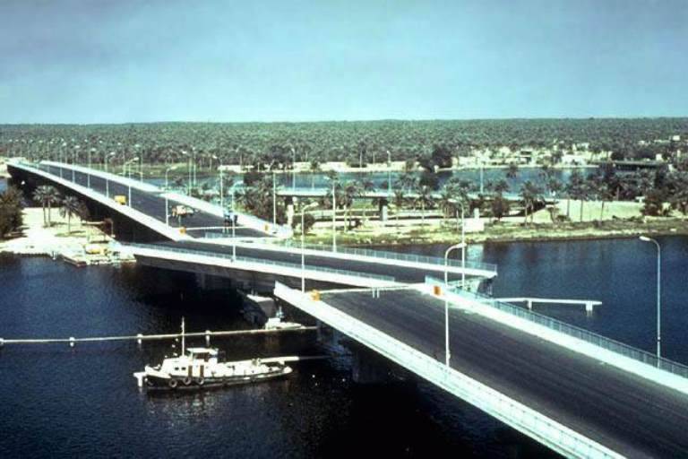
The Shatt al-Arab Bridge on Sinbad Island at its best
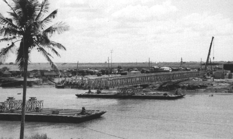
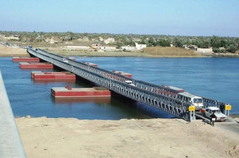
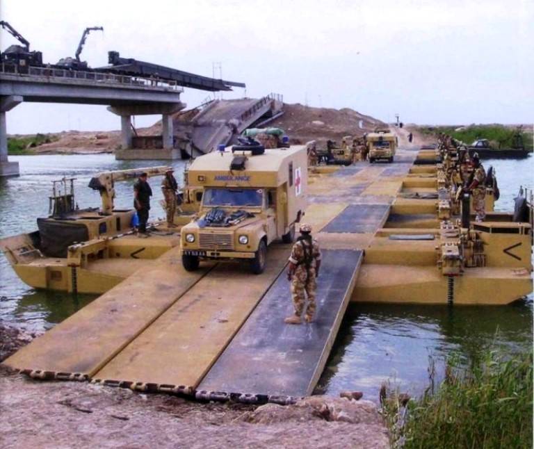
With the outbreak of the Gulf War in 1991, the bridge was destroyed and replaced with a pontoon bridge. Later, in 2003, the pontoon bridge was also destroyed during Operation Telic.
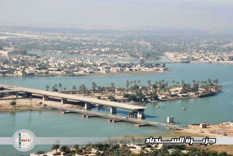
Pontoon bridge over the Shatt al Arab
To restore the pontoon bridge, it needed to be repaired.
But, as it turned out, some elements of the previously damaged pontoon bridge were stolen and used elsewhere on the river as moorings. The repair therefore required most of these elements to be "stolen back". And the British military successfully coped with this task. The necessary repairs were soon carried out and new sections inserted. But this time, in order to avoid new thefts, everything was bolted and welded.
Another bridge of interest was the Aldershot Bridge, an extremely long floating Mabey compact bridge that has been under constant repair for a number of years.
Moving pontoons and sections of Aldershot Bridge
It is interesting to note that a local Iraqi was brought in to support the construction of the bridge with his large mobile crane.
However, the history of the construction of the bridge had a sad ending, because almost immediately after it was completed, the same obliging Iraqi crane operator drove his huge crane across the bridge. As a result of this movement, his truck crane damaged the bridge so badly that the help of miners was required so that the bent, flooded and twisted sections of the bridge could be removed by cutting them with shaped charges. After that, the bridge began to be repaired and restored again.
Lowering bridge sections onto the Flexifloat pontoon at Aldershot Bridge
Damage to the Aldershot Bridge when a truck crane crossed it
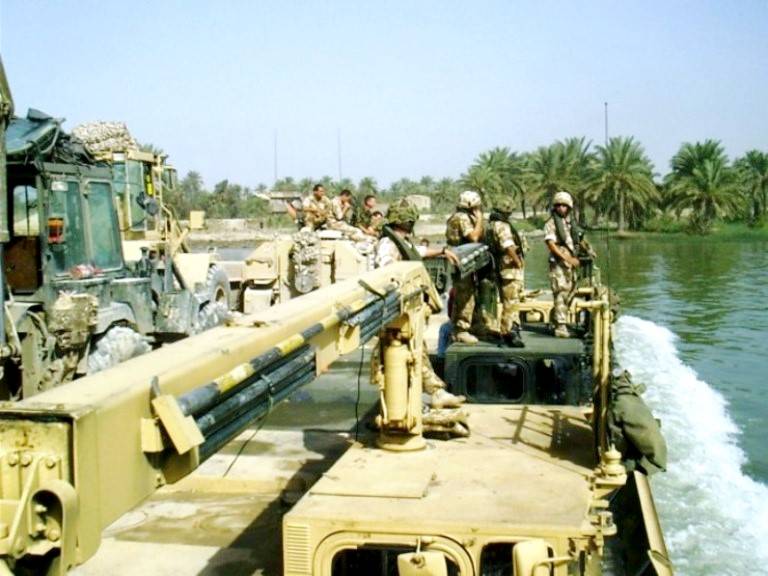
The other equipment used in Iraq was the Mexeflote ferry.
On March 28, 2003, the ferry was delivered to the pier at the port of Umm Qasr. Here he had to transport 232,3 tons of humanitarian cargo from transport ships, as well as various equipment that was used to restore the port.
Transportation of cargo to the port of Umm Qasr
Thus, the pontoon equipment of the British army has gone a long way to solving the problems of timely transfer of heavy support and material support through water barriers so that attacking infantry can successfully carry out offensive and defensive operations.
Therefore, overcoming water barriers with the help of floating (pontoon) bridges and ferries to achieve success in battle or operation for any army in the world today is just as relevant and vital as it was hundreds of years ago.
Information