Pontoon bridges and rafts of the British Army from 1920 to 1945
In the second part of our story, we will continue our acquaintance with the English pontoon bridges, which were developed and adopted into service in the 1920s – 1930s and during the Second World War.
Christchurch - Bridge Equipment Development Center
At the end of World War I, a permanent center for innovation and development of bridge equipment for the British Army was established in the Christchurch military barracks.
The barracks were built in the last decade of the XNUMXth century to house cavalry and horse artillery deployed to defend the southern coast from possible French invasion. Later, the duties of the troops included assisting excise agents in pursuing gangs of local smugglers who traded with France and the local coast between the harbors of Poole and Christchurch.
The barracks were expanded at the beginning of 1918 due to the introduction of sappers.
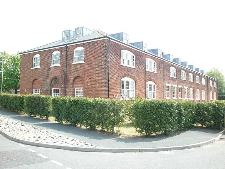
Cavalry Barracks, built in 1795 Christchurch
Continuous development and improvement tanks during the First World War made it clear to the General Staff that the rapid overcoming of tank obstacles will be of great importance during the offensive.
Therefore, in 1918, it was decided to form three special Royal Engineering Tank Battalions. These units were to be the first mechanized units of the Royal Engineers, and their formation was organized in Christchurch in October 1918.
Each battalion was to be equipped with twelve new Inglis Mk II bridges, as well as heavy pontoons needed to support the construction of long floating bridges for the eventual crossing of the Rhine River. In addition, each battalion was to be manned by 48 tanks equipped with the new 21-foot Canal Lock Bridge, also designed by Major Inglis.
After the end of the war, two battalions were disbanded. The remaining battalion was reorganized into the Experimental Bridging Company Royal Engineers on 28 February 1919. Major Gifford Martel, who had previously been involved in the development of the 21-foot Canal Lock Bridge, was appointed company commander.
State of the art Canal Lock 21 Lift Bridge, a suburb of the city of Canton
Thus, in Christchurch was established the most important center of military bridges, located in an ideal location, with good test sites, both inside and outside the barracks. The Stour River flowed near the barracks, which provided the necessary water barrier for the construction of floating bridges and equipment.
However, the Experimental Bridging Company was disbanded in August 1925 and replaced by the Experimental Bridging Establishment, or EBE. The new unit was primarily a civilian institution, although sapper officers continued to work in it.
The transfer to the War Department took place only in 1957, when in January of the same year Sir Donald Bailey became the new director of the enterprise.
When Martel assumed command, his initial mission was to continue testing on the Inglis Mark II rectangular bridge and the Canal Lock Bridge. However, he first had to face the consequences of demobilization, as many of his best people wanted to return to civilian life. Re-entry into military service threatened them with the possibility of being sent to the north or south of Russia, where the British units were still located.
Martel overcame this problem to some extent by using a loophole in the rules to recruit candidates for a three- or four-year term of office. He also ensured that they would not be sent outside Christchurch.
Meanwhile, in late 1920, the Royal Board of Engineering initiated its first major new development - replacing the aging Mark II / Mark III pontoon equipment used with the Mark IV or Weldon Trestle timber beams.
Small open pontoons formed from the bow and stern to create a 21-foot (6,3 m) span had many disadvantages, one of which was unsuitability for use in fast currents. This was demonstrated during the war in Northern Italy, when flooding caused the pontoons to be flooded and sank.
Early proposals for the new pontoon included steel construction throughout to reduce maintenance issues and ensure quick recovery in an emergency.
Using this pontoon, it was possible to create bridges of various configurations.
Thus, two-piece supports, located about 21 feet apart and used with single overpasses at both ends of the bridge, formed a middle pontoon bridge capable of carrying an 8 ton tank.
The heavy pontoon bridge, capable of accommodating an 18-ton tank, used rafts formed from two two-piece supports connected together, with the rafts also being about 21 feet apart. This bridge needed a double overpass at both ends due to the increased carrying capacity.
The lightweight pontoon bridge could be built using single 21-foot pontoons. Also, the equipment of the bridge could be additionally used in the formation of rafts for ferrying troops and equipment along wide rivers.
During the development of the pontoon, its safe buoyancy was increased to about 6½ tonnes, up from 3,5 tonnes for its predecessor.
By 1924, the new bridge had successfully passed all the tests and in 1927 was put into operation under the name Mark IV Pontoon.
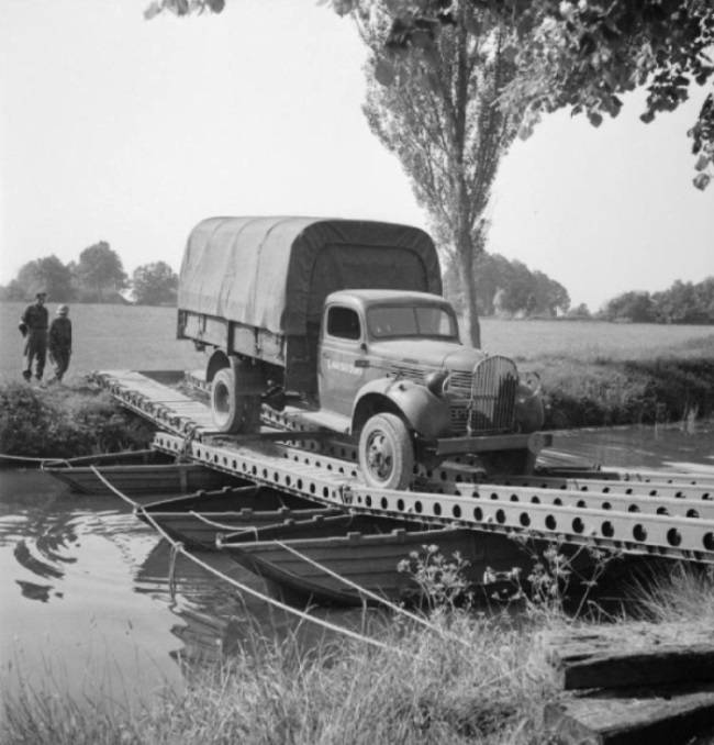
Several years later, a high-strength overpass was put into operation. This was a Mark VI flyover that could be used one at each end of the heavy bridge instead of the double Mark V flyover.
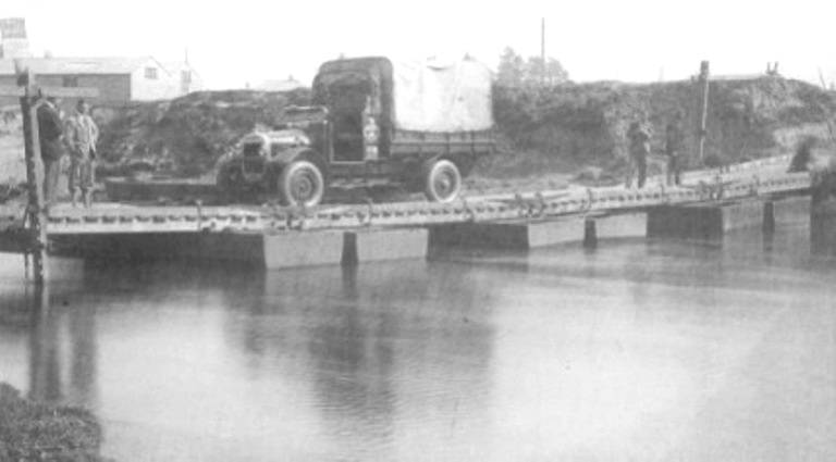
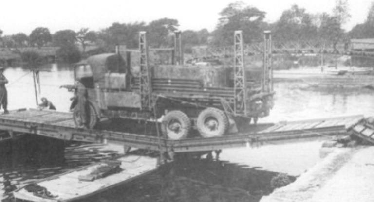
A truck with a lifting capacity of 30 quintals, crossing a heavy bridge formed from Mark IV pontoons and Mark V overpasses.
At the same time in Christchurch was Robot on the method of erecting pontoon bridges across rivers.
As a result, four main methods were worked out.
The first method of formation was to connect the pontoon supports and the superstructure at the head of the bridge in series.
The second - the rafting method, suggested collecting two (or more) pontoons in rafts, and then connecting them, forming a bridge.
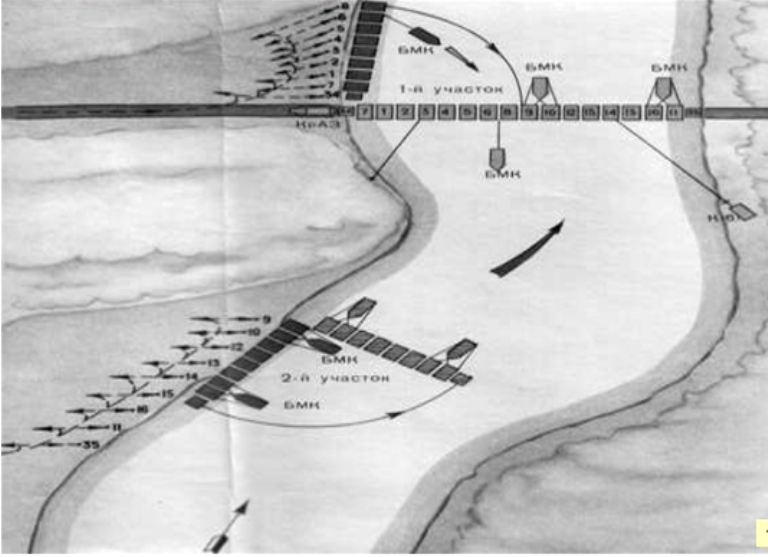
Rafting method in modern design. The bridge from the PMP park is built of two parts (rafts), which are transported to the junction by boats
The third is the "turning method". Along it, the entire bridge had to be assembled next to the coastline, and then turned (installed) into place.
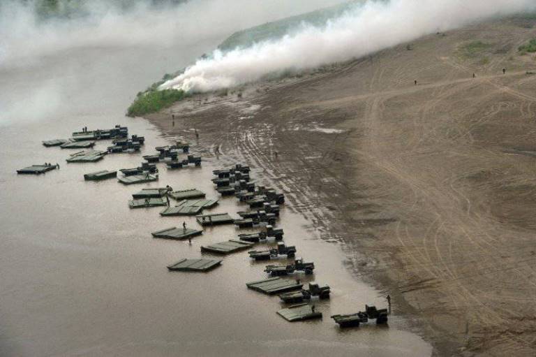
Photo and diagram of the installation of a pontoon bridge from the PMP park by the "turn" method
The fourth method, Booming Out, assumed that the pontoons and superstructure were connected sequentially from the home bank, pushing the growing chain of pontoons forward until it reached the far bank.
In early 1920, the Rawlinson Committee, formed in 1919 to consider the future organization of the Royal Engineers, decided that various bridge equipment used by sappers should be stored and transported by the Royal Army Service Bridge Parks.
In accordance with this recommendation, the new pontoon equipment was transferred to the RASC pontoon bridge fleets (which later became the familiar RASC bridge companies during the Second World War). It was transported in specially modified 3-ton six-wheeled trucks, in contrast to the pontoons and flyovers drawn by horses during the First World War.
Despite the decision of the Rawlinson committee, the equipment for the folding boats and the small box girder bridge, developed later, were retained by the sappers in the divisional companies of the field park.
Kapok assault bridge
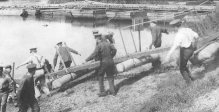
During the First World War, during the campaign in France, light, homemade pedestrian bridges were widely used.
Such bridges consisted of lightweight floats made from gas cans, cork, sheet metal, or any other convenient material, with a simple footpath extending between the floats and allowing infantry to cross river obstacles in a row.
These lightweight floating bridges proved to be so important in the latter stages of the war that engineers at Christchurch were tasked with developing standard equipment to meet these needs.
Trials to make a float of satisfactory quality began in 1920, and a number of designs were tested using, for example, a plug, a cap, and even floats filled with hydrogen.
After numerous tests, by 1923 it was decided to stop at the bridge, in which the canvas float was filled with kapok filler (cotton fiber) and had wooden sidewalks.
This bridge was considered the most suitable, and in the same year it was adopted for the equipment that became known as the Kapok assault bridge.
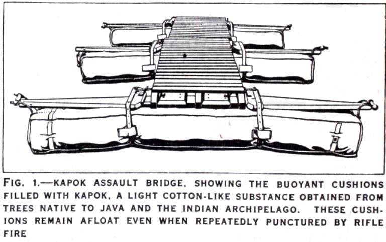
Drawing of the Kapok infantry bridge. The shape of the canvas float and the attachment of the sidewalk to it are clearly visible
Each float was 6 feet 6 "(1,98 m) long and the deck sections were 6 feet 6" long and 1 foot 10½ "(0,57 m) wide.
Thirty spans of the Kapok Bridge could be transported on a truck with a carrying capacity of 3 tons.
The training brochure describes the construction process of this bridge as follows:
“Two people each carried a float, and one person carried one section of flooring. A float was attached to each end of a length of flooring with simple latches. The finished section with floats was lowered into the water. A second deck section was attached to the bank with the first float and then a second float was attached. The bridge was gradually submerged in water until they reached the distant shore. The maximum practical length was 150 feet (45,7 m), but that was only in stagnant water. Any tide, current or wind would make this distance dangerous or impossible. "
The launch of the Kapok Assault Bridge in Christchurch amid heavy pontoons. Photo from the book JH Joyner, One more river to cross
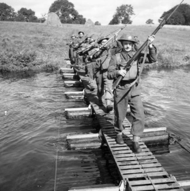
Soldiers of the 8th Sherwood Foresters Regiment cross the river on a small pontoon bridge made of kapok. Dunadri, Northern Ireland, 28 August 1941
Foldable Boat Equipment (FBE) Ferries and Bridges
Foldable Boat Equipment or FBE is a lightweight pontoon bridge equipment used by the British Army and colonial units in the 20s and 40s.
The FBE was adopted by the army in 1928 and has been improved over time in several versions.
It was used extensively during World War II, where it was often supplemented by Bailey's pontoon. The FBE kit, consisting of a boat and foldable equipment, was designed to provide the ability to transport light vehicles across the river to immediately support the assault or hold a bridgehead. It took much less time to build it than to build a heavy pontoon. It was inevitably less durable, but ideally suited to its task.
Thus, it made it possible to overcome the inevitable delays that occurred before the middle pontoon bridge could be deployed and completed.
At the initial stage, a folding boat made of a new aluminum alloy, delivered from Germany, was examined. On its basis, after several tests of the ball, its own version was developed.
The design of the boat, indexed Mk III, was quite original. It was made foldable and consisted of three pieces of plywood 0,5 inches thick, which made up the bottom and two sides of the boat, which were attached to the bottom with solid fabric loops. When folded, the boat was completely flat for easy transport and storage.
Its carrying capacity was 391 kg, and it could carry 21 passengers: 16 paratroopers, a boat commander and a crew of four. The movement was carried out either with the help of oars, or using the Coventry Victor outboard motor with a capacity of 7,5 liters. With. In conditions of overload, it was possible to load up to 30 people.
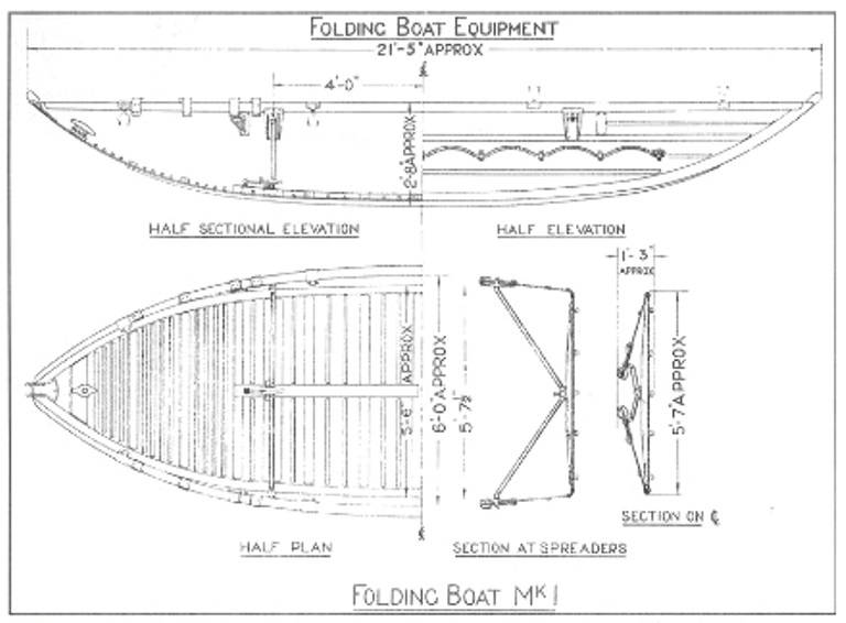
Folding boat from the FBE kit and its assembly diagram. Drawing from the book "Military Engineering" Volume III, Part II, 1934
The boat could be transported on four-wheeled trailers or in bridge trucks. As a rule, three platform boats were transported on a trailer, and up to seven boats on trucks. Sixteen soldiers were required to carry and launch one boat by hand.
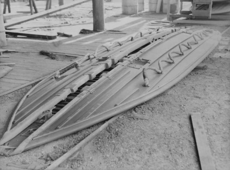
Folding Boat Equipment Mk III, folded for transport.
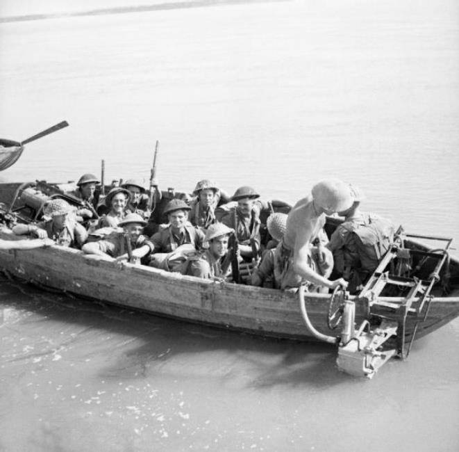
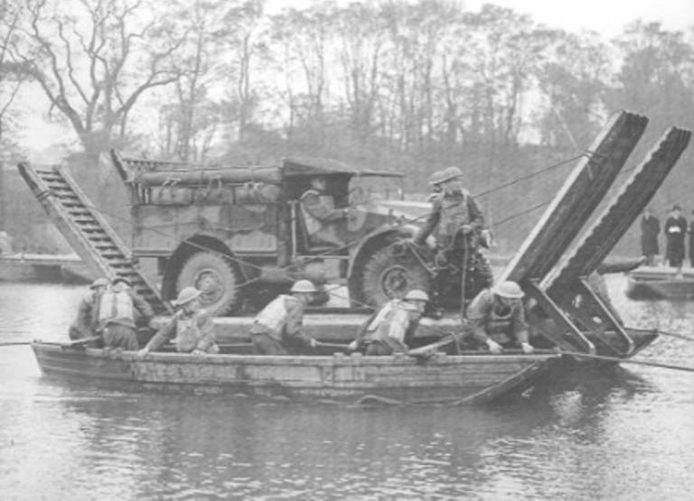
The FBE is used as a ferry with an outboard motor mounted on a prefab frame. Burma, February 1945
With the addition of a deck row and connecting hardware, the base foldable boat can be used as an FBE car raft, FBE deck raft, or FBE bridge.
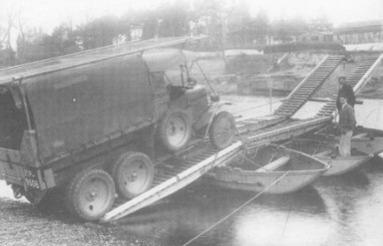
The FBE car raft could withstand vehicles weighing up to 3 tons and used two boats connected by two long transoms located across four planes and 6 track tracks. The center pair of track tracks were 14 feet (4,26 m) long, and the front and rear loading ramps (tracks) were shorter at 9 feet (2,74 m) in length.
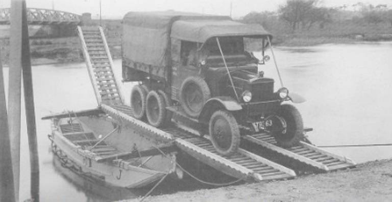
Foldable end-loading boat equipment or car raft. Photo from the site "Virtual Museum of Royal Engineers" (IWM)
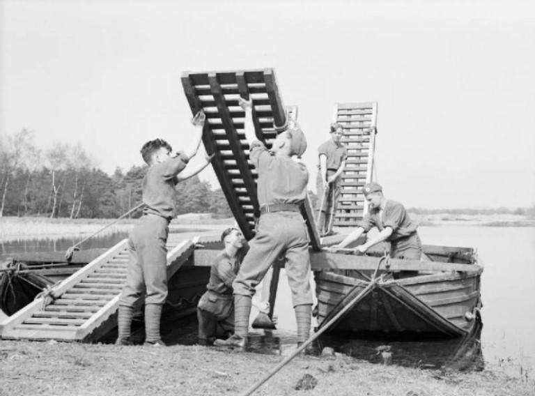
Royal engineers fold car raft
The FBE deck raft used 3 boats and large ramps. In this case, the boats were located across to the deck of the raft. In the absence of ramps, the raft had to be operated between a berth built on both banks of the river. The berth usually consisted of an anchored deck raft, and the coastal boat was replaced by an FBE flyover, connected in turn to the shore by a deck strait.
The carrying capacity of the raft was 4,5 tons.
Using the Folding Boat Equipment (FBE) kit, a third boat and ramps as an onshore loading raft, the sappers built a deck raft
The FBE bridge consisted of several interconnected FBE deck rafts forming a continuous bridge span and an FBE flyover. The entire structure was completed by a folding "reconnaissance boat", from which they usually carried out reconnaissance of the opposite bank.
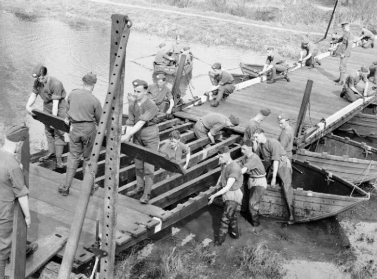
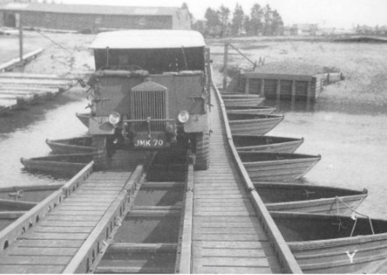
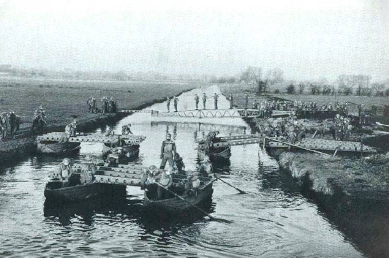
Royal Engineers build a foldable boat equipment (FBE) bridge during maneuvers
FBE bridge in action
FBE equipment was modernized in the early thirties of the twentieth century.
The design of the Mk II had minor changes. The boats of the two versions were almost identical, the roadbeds were made wider, the carrying capacity of the deck raft was increased to 5,2 tons.
The Mark II version of the FBE raft tested by "Ministry people". Truck on raft loaded with latest version of Kapok Raft hardware
The video below shows the same raft in dynamics. This fragment also shows the construction of a temporary "dry" bridge.
In 1938, the newly formed Mobile Division, which later became the famous 1st Armored Division, announced the following requirement: a new floating bridge "must carry all our divisional transport, except tanks." That is, it was a class 9 bridge.
It was decided that the fastest way to meet this new requirement would be to redesign the folding equipment of the Mark II boat.
The Mk III was introduced in 1938.
The bridge in the Mk III version was quick and easy to install. This contributed to it becoming the standard lightweight bridge equipment in 1939 to be widely used during World War II. The bridge was a significant improvement, raising the bridge's carrying capacity to class 9 (approximately 11 t). The stability of the bridge on the water was ensured by its anchors, which allowed the crossing to work well even with fast currents. The FBE could be serviced and used indefinitely.
The Mk III FBE could also be used in a number of other configurations, including a class 5 deck raft (6,3t), a class 9 deck raft and a shore loaded class 9 deck raft. Any of them could be used as a raft with outboard motors. Finally, the class 9 bridge consisted of several deck rafts connected together by a semi-floating platform and an FBE flyover, just like the Mk I variant.
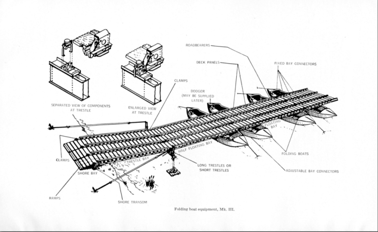
The main parts of the Mk III FBE bridge: 1. Folding boats. They could be used individually as an assault boat, or in combination with two to four boats to form a raft or ferry. 2. The superstructure or deck is the same for both the rafts and the bridge. 3. Trestles, which are used to secure each end of the bridge. 4. Anchors.
Eccentric load test on the Mark III FBE class 9 version
Deck versions of the Mk III used steel road structures that weighed 380 lb (81 kg) each (see photo below) and 3 ft 10,5 in. (1,18 m) long Douglas Fir deck panels. The section connectors have been designed to limit load deflection and the Mk III FBE ramp has been improved to withstand Class 9 loads.
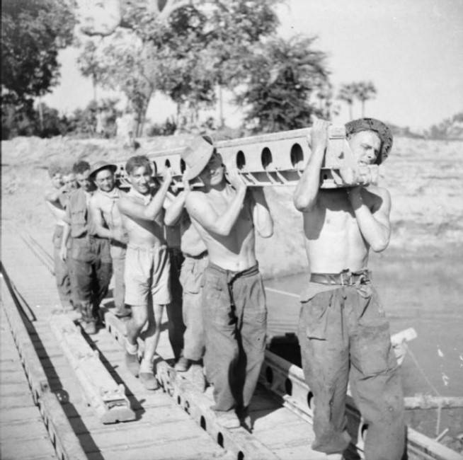
Soldiers Carrying FBE Structures
The photo below shows the foldable boats, raft and FBE bridge that were used during World War II.
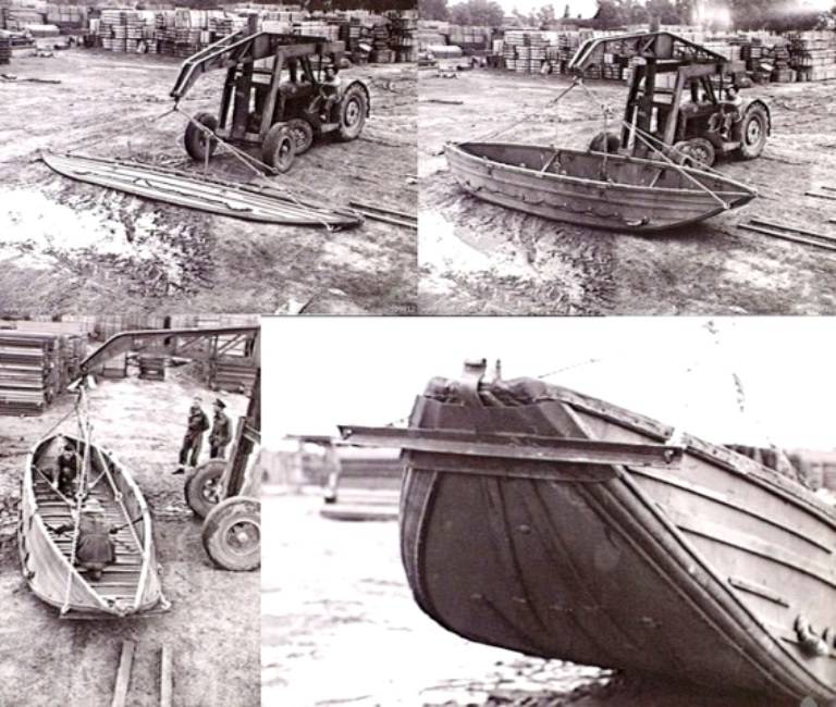
The process of transferring the folding boat model Mk III to the working position
FBE Mk III "David" Class 9 Bridge at Vernon, August 27, 1944.
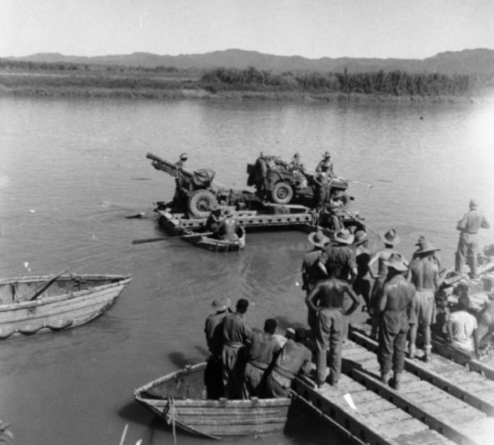
A 25-pound cannon and a jeep are transported on a Mk III FBE pontoon raft down the Kalapanzine River from Butydaung. Burma, January 1945
The scene from the training film shows the process of laying the FBE bridge during the exercise
The video below shows the construction of the FBE Bridge and the Small Box Girder (for infantry) during the 1940 exercise.
1930s pontoon bridge
In November 1936, work began on the Matilda II tank. The new pontoon bridge project, commissioned in early 1936 by the Royal Board of Engineering and Signaling, was the first pontoon bridge influenced by the appearance of a new tank.
Initially, it was assumed that the new bridge will have a carrying capacity of 14 tons, but if necessary, it could be strengthened to withstand the load of 20 tons. The bridge, consisting of a Mark V pontoon and a Mark VII flyover, was needed to replace the Consuta or Mark IV pontoon and the Mark V and VI flyovers developed in the 1920s.
Various designs were considered and model tests carried out at the National Physical Laboratory. Then it was decided to accelerate the program to carry out full-scale tests in the summer of 1937. Test equipment orders were placed so that the first six pontoons were delivered to EVE in January 1938.
By this time, however, the General Staff decided to increase the carrying capacity to 18 tons, with a possible increase to 24 tons, in order to ensure the passability of the new Matilda II tank. The change in requirements prompted an insane recalculation and redesign, and the pontoon had to be lengthened by about 3 feet.
It was decided to transport an 18-ton cargo on rafts with two piers and a 24-ton cargo on rafts with three piers. Each pontoon pier consisted of two pontoons connected stern to stern.
Full-scale trials took place in 1937 at Wyke Regis Bridge Camp in Dorset, with military test equipment ordered straight from the drawing board.
The equipment was accepted soon after. The design was refined and over the next few months contracts were awarded to build a new bridge.
The conventional bridge construction method began with the construction of a flyover using the new Mark VII flyover, which differed only in detail from the previous Mark VI. The required number of rafts were then built on the bank, each about 21 feet (6,3 m) long, which were rolled out one at a time to connect at the head of the bridge.
The coastal tip of a version of the 24 Mark V class pontoon bridge entered service in 1939. Drawing from Military Engineering Vol III, Part II, 1940.
The rafts, built with two pontoon piers for class 18 construction and three piers for class 24, were connected to each other using special raft connectors. These built-in tubular steel struts were designed to limit the movement of the joint while transferring the load through the joint between adjacent rafts.
This equipment could also be used to construct a class 30 coastal raft (which became known as the batwing raft) by connecting two rafts with three piers (six pontoons) together and then removing the two outer supports. The four remaining pillars formed the raft, with the flooring protrusions at each end of the raft acting as ramps.
The bridge was accepted into service and entered the disposal of the field forces in 1939.
It was good equipment as it was originally intended, but it suffered from the protracted design phase. During the operation of the bridge, it emerged that the third pontoon berth required on every raft for the Class 24 bridge, which soon became the norm with the increasing weight of vehicles, was an uneconomical and cumbersome construction method.
The bridge was never used operationally and in fact, when it entered service, became a ready source of Mark V pontoons for use with the Bailey Pontoon Bridge.
Also a big disadvantage of the new equipment was that it used an overpass. It was noticed that the unpredictable state of the river bed on which the flyover stood, as well as a break in the cable that held it, could lead to overturning of the tragus support and the destruction of the bridge.
Captain S. Stewart, who became EBE Superintendent in November 1936, recalled:
“During the tests of the Mark V Pontoon prototype at the end of 1936 in Christchurch, we had a bridge accident. When an experienced 17-ton tank crossed the overpass onto the floating bridge, to everyone's horror, the overpass's support cable broke, and the tragus support slowly slipped off the shore. But, fortunately, it stopped as soon as the tank was at the equilibrium point. To get the prototype tank back to the shore, we had to use the old Heavy Tank Mark V ** that we had at our disposal. "
Later, the problems associated with the use of flyovers were solved with the help of a special compartment for long landings that extended from the coast to the very first floating bridge span.
This compartment eliminated the need for a flyover.
It consisted of a four-girder box-type bridge with a length of almost 42 feet (12,6 m). The trusses were formed from a center section and two outer sections, very similar to the SBG bridge sections, but slightly shorter in length. The sections were connected to each other by joining chrome-molybdenum steel dowels with corresponding holes at the end of the adjacent section. Each dowel had a machined neck into which a stainless steel retaining plate was inserted, thus firmly holding the sections together.
Long landing pad,
designed for the Mark V pontoon bridge equipment
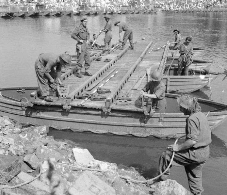
Bailey's pontoon bridge and raft
The most famous bridges of the English army during the Second World War were the Bailey Bridges.
The design of these bridges was so adaptable that it could be used in both a floating pontoon and a raft configuration. Since the Bailey has no lugs below the bottom chord, it soon became clear that this would make it ideal for use with pontoons.
Design work began in 1941.
The final configuration used a 30-foot (9,15 m) single Bailey section supported by two pontoons. The bridge was distinguished by its speed of aiming, ease of dismantling and the interchangeability of parts with a standard Bailey bridge.
These pontoons consisted of three parts, where the front and rear were the existing Mark V pontoons. But a new Bailey Center pontoon was designed and introduced to support more weight.
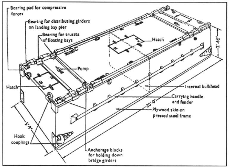
Bailey Center pontoon, which was used in bridges with two Mark V pontoons
An important design aspect that needed to be addressed was the degree of rigidity that would be acceptable for the bridge girders. A certain stiffness was obviously necessary to distribute the load across the multiple floating compartments of the bridge, but full stiffness would result in excessive bending moments, even with only waves or swell.
After much research, a limited articulation system was adopted in which the floating compartments were connected together using special connecting end posts, with a conventional pinned connection at the bottom level and a butt joint at the top. This allowed the connecting posts to transfer lateral forces between sections and resist sagging moments, as well as preventing jamming between adjacent sections.
The standard design for a Class 40 bridge combined the required number of floating compartments, each of which consisted of a 20-foot Center Bailey single pontoon supported by two Mark V pontoons.
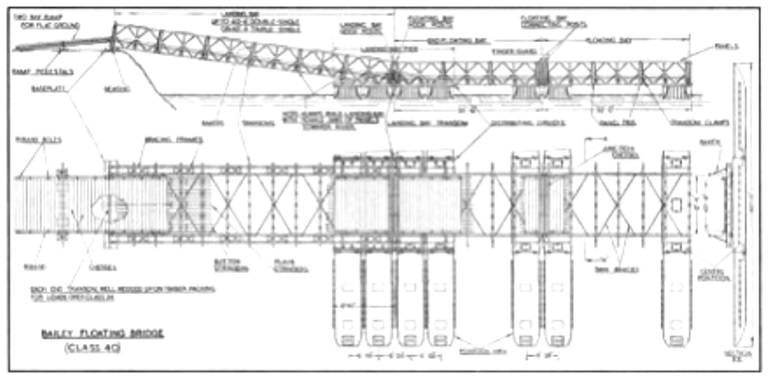
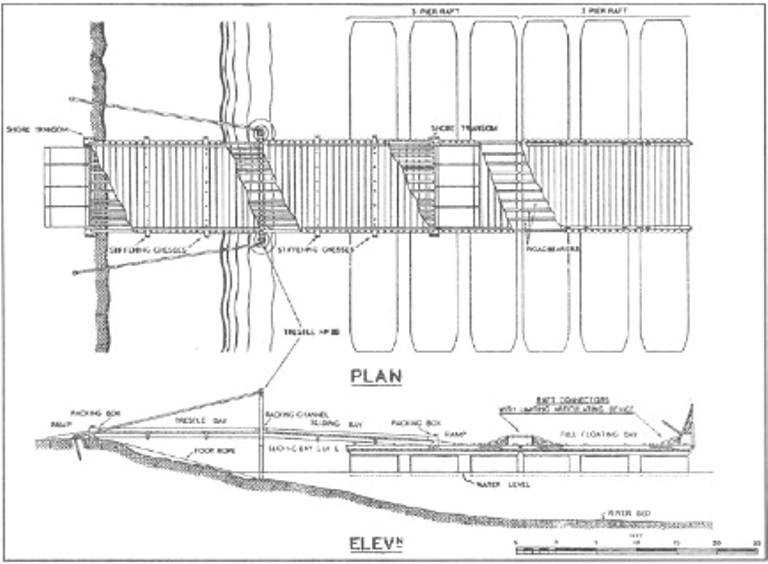
Drawing of a Class 40 Bailey Pontoon Bridge and Shore Pier for Shoreline. Drawing from the book Military Engineering. Volume III, Part III, 1944
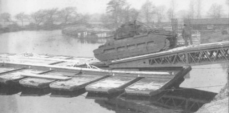
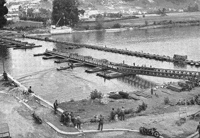
Bailey Pontoon Bridge in Vernon, August 1944
By the end of November 1941, the 320-foot (92 m) Bailey Floating Bridge was ready for military trials using a tank as live cargo.
Testing a bridge on the River Thames at Wallingford. During the tests, one of the new hook legs failed, which was used at the end of the landing compartment to transfer the load to the transom of the landing compartment. But a quick repair and fabrication of a replacement in the EBE workshops within a few days allowed the test to be completed.
A key feature of the Bailey Pontoon was its landing jetty - it was the only span from shore to bridge level, eliminating the need for cumbersome and unreliable bridge overpasses. At the pier for landing, 4 assembled pontoons were used, which is clearly seen in the photo below.
The Bailey Bridge over the Meuse River in Maaseik, called the "Bristol Bridge", was built on January 27, 1945 by the 224th Royal Engineers Field Company
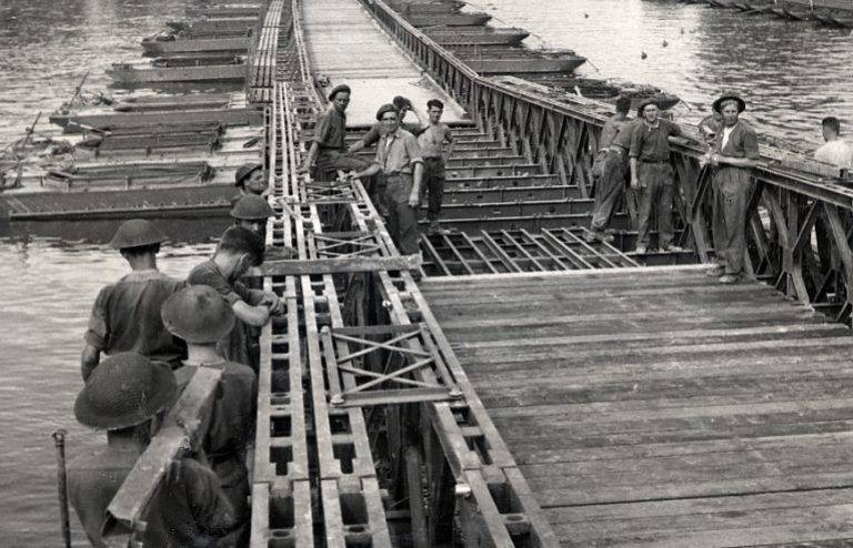
The Bailey Pontoon Bridge was built by lowering the finished sections into the water and towing them into place using small boats. The most commonly used boat was the Royal fleet PN as shown in the photo below.
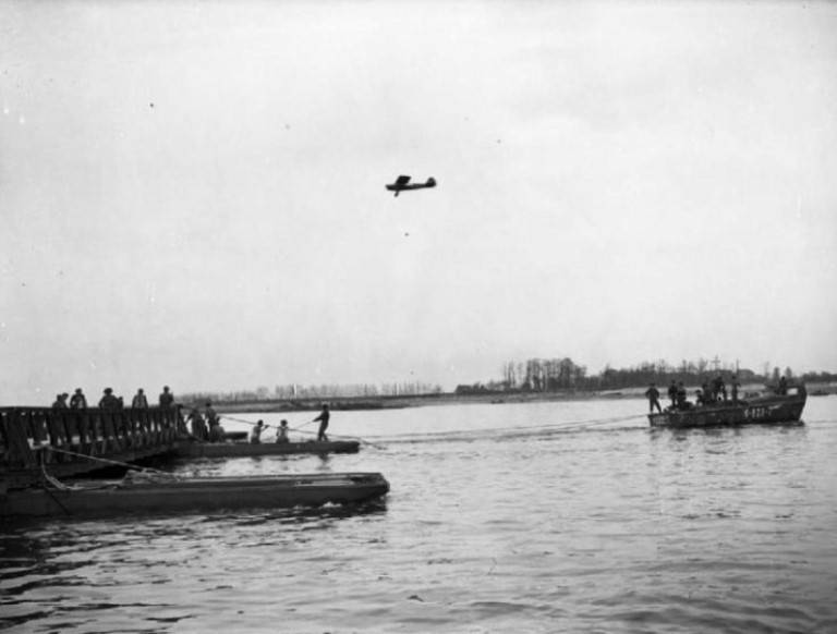
Landing craft helping to erect a section of the bridge after being towed from the shore
The standard Bailey pontoon was of class 40 (carrying capacity 36 t for tracked vehicles and 42,6 t for wheeled vehicles), but it could be increased to class 70 (62,6 t for tracked vehicles) by doubling the width of the bridge and using additional pontoons.
Raft class 50/60
As versatile as the Bailey Bridge was, it was not suitable for fast construction and crossing of equipment, especially in the early stages when crossing water obstacles. The existing FBE was faster, but lacked the carrying capacity for anything other than light vehicles.
Therefore, in 1943, a new study began to create a raft capable of fast construction and with a carrying capacity sufficient for a Churchill tank.
Work on the new raft, class 50/60, or, as it was originally called, class 48/60, was started by EBE at the very beginning of 1943 with the expectation of crossing the Rhine River in an assault in the future before crossing the large bridges.
It was required to provide a heavy raft capable of carrying, as indicated above, the Churchill tank. At the same time, the raft should have been easily and compactly transported, quickly launched and assembled, and also easy to operate.
The raft was eventually built using four or five pontoons, providing a 50 or 60 class capacity.
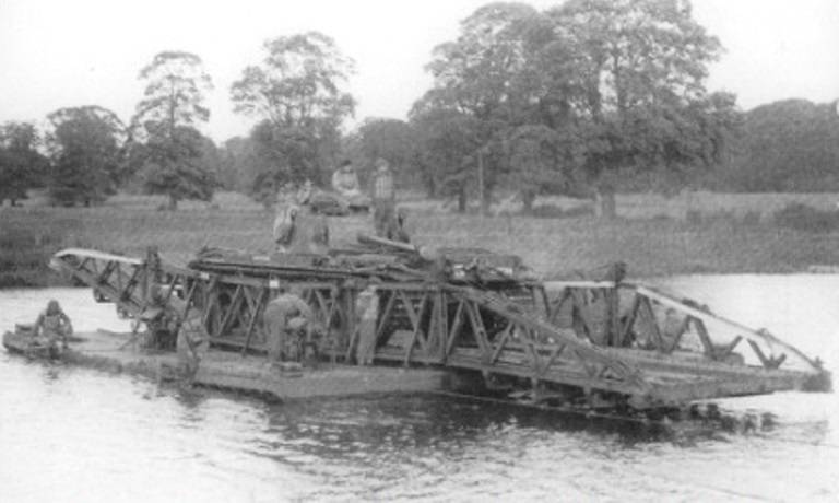
A 50/60 class version of a raft with four class 50 pontoons being tested on the Thames
For simplicity, each pontoon block was identical and each carried its own superstructure of two hinged panels that were folded onto the deck and lifted into place after the pontoon was launched. Each pontoon was towed on a special trailer.
The raft was usually used as a free-floating ferry, using two DUKW amphibians or four motorized tugs to propel it. If operated as a ferry, it was powered by four 22 HP Johnson outboard motors. with., installed on special brackets and transoms.
Alternatively, it can be moved across wide tidal rivers using the two Wild Kite balloon winches located on the riverbank.
Also provided were class 5 driveways running parallel to the main carriageway and outside the panel beams and located on the fore and aft decks of each pontoon. These driveways were accessed by FBE Class 5 Raft ramps, but the driveways were infrequently used because the line guides were installed at the outer edge of the carriageway, preventing them from being used when the guides were themselves in service.
CSR raft for immediate support
This raft was also designed by EBE in 1943 especially for assault river crossings.
Although the Mark III foldable equipment introduced shortly before the war could be used to create a Class 9 coastal loading raft, it was a cumbersome affair involving six foldable boats.
The FBE, of course, was designed primarily as a bridge, and the more common form of the FBE raft consisted of two interconnected floating bridge sections operating between two flyovers.
On the other hand, the CSR was faster to build, easy to operate, and had to be deployed early in the forcing phase. The pontoons were transported on wooden sleds lined with steel, which could be removed from vehicles and then towed to the ferry on any suitable armored personnel carrier or half-track chassis.
When organizing the crossing, it was required to slightly modify the approaches to the river's edge. And this meant that the equipment could be landed on the enemy coast in a very short period of time.
Although it was mostly class 9 equipment, the raft had sufficient buoyancy to carry individual vehicles above class 9. This made it possible for the attacking troops to receive support from their armored cars and reconnaissance vehicles, vehicles for various purposes, and even field artillery tractors with towed anti-tank guns. 17 gauge.
Closed-end CSR raft using Mark V pontoons loaded with 11 ton truck
The equipment was operated as a floating raft with two or four propellers. It could also be used as a ferry ferry with two cross ferry cables, driven either by onboard power units or via a winch.
Like all equipment, it was followed by modifications and improvements.
The raft with three piers (pontoons) made it possible to install two additional propulsion systems, and also provided an additional freeboard and a buoyancy reserve.
A class version 12 was also introduced.
Finally, by the end of the war, the Mark II CSR was produced with welded aluminum alloy beam supports and cast alloy deck panels.
This was the first time that an aluminum alloy had been used to any extent in a British floating bridge, but after a few years such use, with all the benefits it brought, became commonplace.
Brushed bridge and Indian mat bridge
In 1926, the commander of the Experimental Bridging Company (EMU), Major Gifford Martel, proposed the option of a lightweight matte bridge.
As G. Martel later recalled, it was
"An attempt to reduce the eight to ten hour delay that occurred from the time the infantry crossed the river barrier using their Kapok assault bridges until the completion of the middle pontoon bridge that provided the support vehicles for the crossing."
The bridge was a solid mat, consisting of plank panels 2,1 m long and 3,8 cm thick, which were interconnected by overlays. Short planks raised 45 ° were attached to both ends of the decks to improve the flow of water under the mat and prevent water from running down the deck.
Thus, the bridge floated on water and worked on the principle that when a vehicle crossed at a reasonable speed, it would always climb onto a part of the mat that had not yet been flooded.
Various forms of longitudinal stiffness were used to bring the flexibility of the mat to reasonable limits.
The need for this became apparent after the first test, when a six-wheeled Morris car drove over the bridge. The car was moving at about 10 miles per hour when the rug in front of it formed an excessive wave. This caused the vehicle to decelerate to the point where it eventually came to a stop and slowly sank.
The problem was easily overcome, but the final version of the equipment turned out to be quite heavy and cumbersome, and further development did not go.
However, this principle was revived during World War II, first as the Indian Mat Bridge, then as the Clover Floating Airstrip and finally the Swiss Roll, a device designed by Sir R.M. Hamilton to take trucks ashore on the beaches of Normandy.
In September 1939, similar experiments using the same principle were carried out by the 4th Field Company of Bengal Sappers. They formed a raft from bamboo lattice and a large tarp, the edges of which were folded over the straw filling to form a waterproof edge of the rug. Steel channels were placed on a bamboo lattice, which served as a support for the wheels of a truck weighing up to 3 tons, which successfully sailed on a raft.
Then the bridge version of the matt raft was successfully built and tested on loading. About a year later, a shortage of all types of bridge equipment in India led the Army Headquarters to place an order for the experimental Mat Bridge in Lahore.
The design of the Class 5 bridge had to overcome many challenges, including joining the tarpaulin to create a bridge that crosses the 200-foot (60 m) obstacle, the difficulty of securing longitudinal strength, and satisfactory replacement of the straw filling that was easily waterlogged.
The problems were eventually resolved, and a bridge built across the Jamna River in Delhi in early 1941 used kapok bags instead of straw.
After further development, the bridge did indeed go into production, although the rotting of several tarpaulins during storage at the factory caused some problems. By the time the equipment became available to the units, other, more advanced bridge equipment had entered service.
And as far as is known, the Indian mats bridge has never been used in combat.
Development work on this topic was also carried out in the UK.
In 1943, a 30-foot raft was successfully tested, built of beams, floats for kapok and tarpaulin. Later, a 150-foot bridge was designed, built in the same way. It was aimed across the Stor River and successfully withstood class 9 loads.
One of the versions of the 9th class bridge with Indian mats, built in the UK. To the left of the bridge you can see a 50/60 class raft
Further testing of the bridge was carried out, during which the floats for the kapok were removed and the alternating barrels were displaced first to one side and then to the other to increase the area of the canvas supported by them.
Replacing the steel expanders used in the Indian version with baskets significantly increased the dimensions and weight of the EBE version. The bridge was not adopted for service.
An interesting result of the early work on the Mat Bridge in India was the final design and manufacture of the Clover floating airstrip, built on the same principles and using, in the first version, tarpaulin with pipe and timber decking.
According to the recollections of Lieutenant Colonel Walker of RE, the Swordfish successfully landed on this runway in the summer of 1944. Whether this was the only landing or not, the lieutenant colonel did not say.
I would like to finish this part of the story with a specific example of the use of pontoon bridges in World War II.
Crossing the Seine
By the end of July 1944, the Anglo-Canadian Allied forces had broken through to the Seine River.
The Seine is a wide river crossed by several hundred bridges. However, most of them were destroyed or badly damaged by the Germans. This destruction posed a serious obstacle to the Allies' advance towards the French border and from there to the Netherlands. Speed in crossing the river was of paramount importance in order to maintain the momentum of the Allied offensive and thus deprive the enemy of time to reorganize their forces to defend the river line.
When planning the landing operation of allied forces in France, they took into account that such a situation is quite possible. Therefore, the units were specially trained to overcome water obstacles using floating equipment.
As part of the British troops, two bridge columns were formed, each of which had more than 360 vehicles and a sufficient number of assault boats, equipment for rafting and building bridges to support the assault crossing with one corps on the front of the division.
The 21st Army Group's plan for the crossing was for the 2nd British Army to attack the right flank: XXX Corps on the right, near Vernon, and XII Corps on the left. At the same time, the 1st Canadian Army will attack the left flank, between the XII Corps and the sea.
The 43rd British Division was supposed to lead the XXX Corps offensive and on 24 August, according to the plan of Operation Neptune, began a 90-mile approach to the river.
The next morning, the forward battalion approached Vernon and found that the enemy had retreated from the city, but concentrated on the far bank of the river. The road and rail bridges across the Seine were destroyed. It should be noted that it was these bridges that were destroyed by the Allies in order to stop the retreat of German forces, but the Germans managed to retreat.
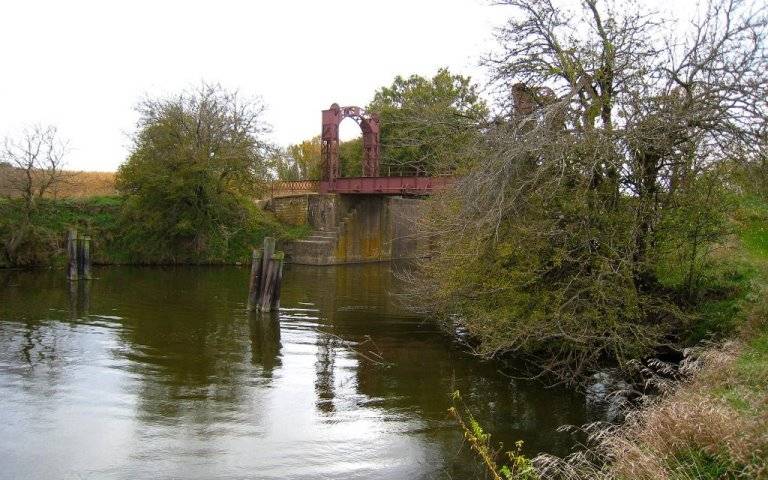
The railway bridge over the Seine at Vernon was destroyed on May 7, 1944 by seven P 47 bombers, and the road bridge on May 26.
Since the bridges were on the main supply routes needed to move the Allies forward, swift replacement was of the utmost importance.
The advanced troops approached the river bank on the morning of August 25, and the assault began at 19:00 on the same day. The assault boats that took part in the crossing were equipped with detachments of the 583rd RE field company.
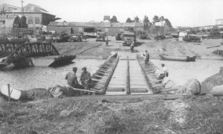
FBE Bridge and Class 40 Bailey Bridge Construction Site
By 22:15 p.m., 43rd Division engineers had been given permission to begin construction work on a Class 9 FBE bridge near the site of the demolished permanent bridge.
By dawn, the forward battalions were able to establish bridgeheads, despite strong enemy resistance and many setbacks. Meanwhile, all the rafts needed for the bridge were built overnight, as enemy machine-gun fire along the bridge line made it completely impossible to build the bridge during the day.
Indeed, early attempts to place rafts on the bridge resulted in about two-thirds of the crew of each raft being killed or injured. By noon, about half of the rafts were attached to the bridge, but enemy fire was so intense that Lieutenant Colonel T. H. Evill, who was in charge of the bridge's construction, was forced to stop all robots on his instructions.
But in the evening, the advancement on the bridgehead somewhat eased the situation, and the work continued.
The bridge was finally completed by 17:20 p.m. on 26 August, and the first vehicles and support weapons moved across it.
But for the further offensive, the troops needed heavy equipment, especially tanks.
The construction of two Bailey Class 40 pontoon bridges, allowing armored vehicles to cross the river, began on August 26, even before the construction of the FBE bridge was completed. The speedy completion of the Bailey Bridges remained of the highest priority these days.
The first bridge at Vernon was completed by the end of the next day. Immediately thereafter, tanks and equipment from the 11th Armored Division began crossing the bridge, which was 694 feet (208 m) long. On that day, a number of tanks were ferried across the river by RE 584 on Bailey's rafts.
But after the bridge was completed, the company’s engineers were able to focus on building a second Bailey Class 40 bridge north of Vernon, which was completed by noon on 29 August.
The length of this bridge without ramps was 736 feet or 220 m.
It is interesting to note that the bridges were given their own names. Thus, the first bridge in the north of Vernon was named “Saul”, and the class 9 FBE bridge and the other Bailey bridge in Vernon were named “David” and “Golliaf” bridges, respectively.
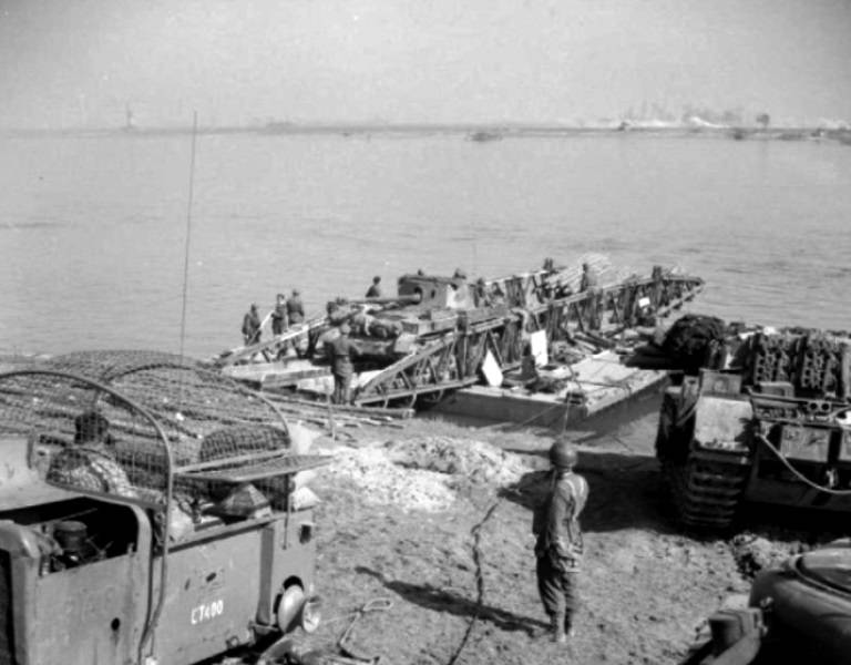
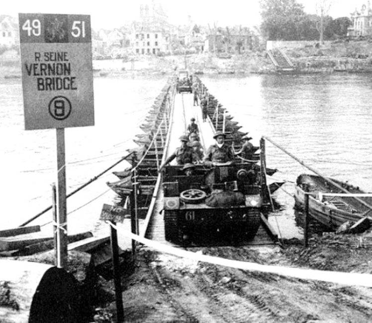
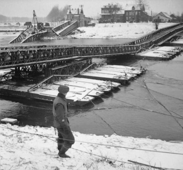
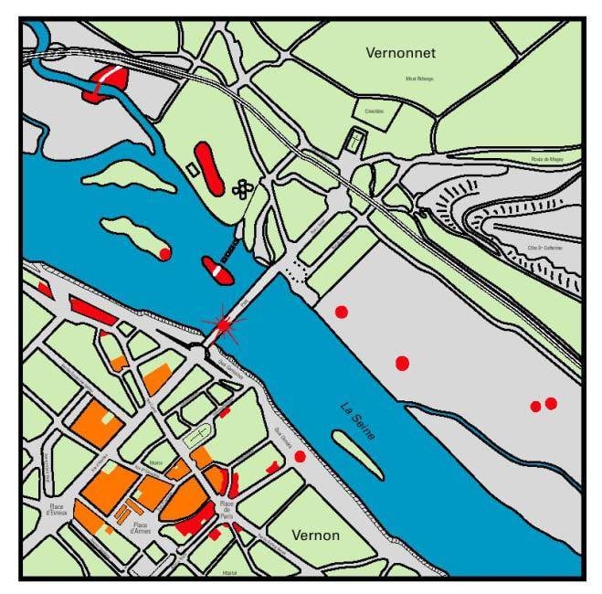
Bridges "David" and "Golliaf" across the river. Seine at Vernon
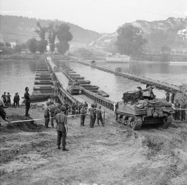
51st Shermans cross the Seine at Vernon across the Bailey Bridge
The video below shows footage of the destroyed road bridge in Vernon and episodes of the construction of the Class 9 Bridge and the Bailey Class 40 Bridge, as well as the crossing of troops and equipment.
Thus, by the end of World War II, in order to successfully solve the problems of overcoming water obstacles, the British sappers were armed with different types of bridges: from light assault infantry bridges to heavy Bailey bridges.
Also, until the end of the war, the British pontoons worked out various methods of building pontoon bridges and the tactics of their use.
The ending should ...
Information