Proposals and reality: project of carrier-based fighter from RSK MiG

134

Perspective layouts aviation equipment from RSK "MiG"

Currently, only 4 generation fighters are in service with the Russian carrier-based aviation. In the medium term, the fleet of such aircraft will need a complete renovation due to physical and moral obsolescence. In this regard, for a long time, the issues of creating a carrier-based fighter of the next 5th generation have been studied. Recently it became known that RSK MiG is working on its own version of such a machine. Moreover, the aircraft is proposed to be supplemented with a highly efficient UAV.

Layouts and news


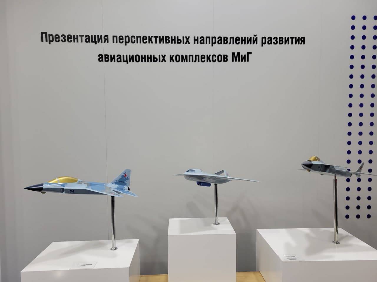
During the MAKS-2021 salon, MiG Corporation held a "presentation of promising directions for the development of aviation complexes." Three scale models of previously unknown aircraft became its central element. They were designated as "light multifunctional aircraft", "multifunctional shipborne fighter" and "multifunctional shipborne UAV".


The layouts made it possible to understand the general features of the proposed machines, but details were not available. In particular, the expected tactical and technical characteristics, combat capabilities, etc. were not specified. Information of this kind appeared the next day after the salon was closed. Already on July 26 RIA News told about new projects - information was provided by an unnamed source in the military-industrial complex.

It is reported that RSK MiG has begun development of a new 5th generation carrier-based fighter. At the moment, the project is at the stage of computer modeling, and the appearance of a prototype is expected over the next few years. Some technical and other details were also provided. The size of the aircraft will correspond to the existing MiG-35. The glider and other units will be built using stealth technology. The possibility of creating an aircraft with vertical take-off and landing is being considered.


Deck Fighter

In parallel with the fighter, a carrier-based UAV is being created - both vehicles will become part of a single aviation complex. A drone with a takeoff weight of more than 10 tons will work together with a fighter as a so-called. faithful follower. With its help, it is supposed to strike at various targets or carry out refueling in the air. When creating such a UAV, it is planned to use the experience of creating the Skat product.

Later, in early August, RIA Novosti revealed new details of the project, also obtained from anonymous sources. In addition to previous news reports, it was reported that the 5th generation fighter will have a number of distinctive features. So, he will be able to make a supersonic flight without using afterburner. with equal efficiency to work on ground and air targets, and the implementation of combat missions will be simplified through the use of artificial intelligence.

Possible appearance


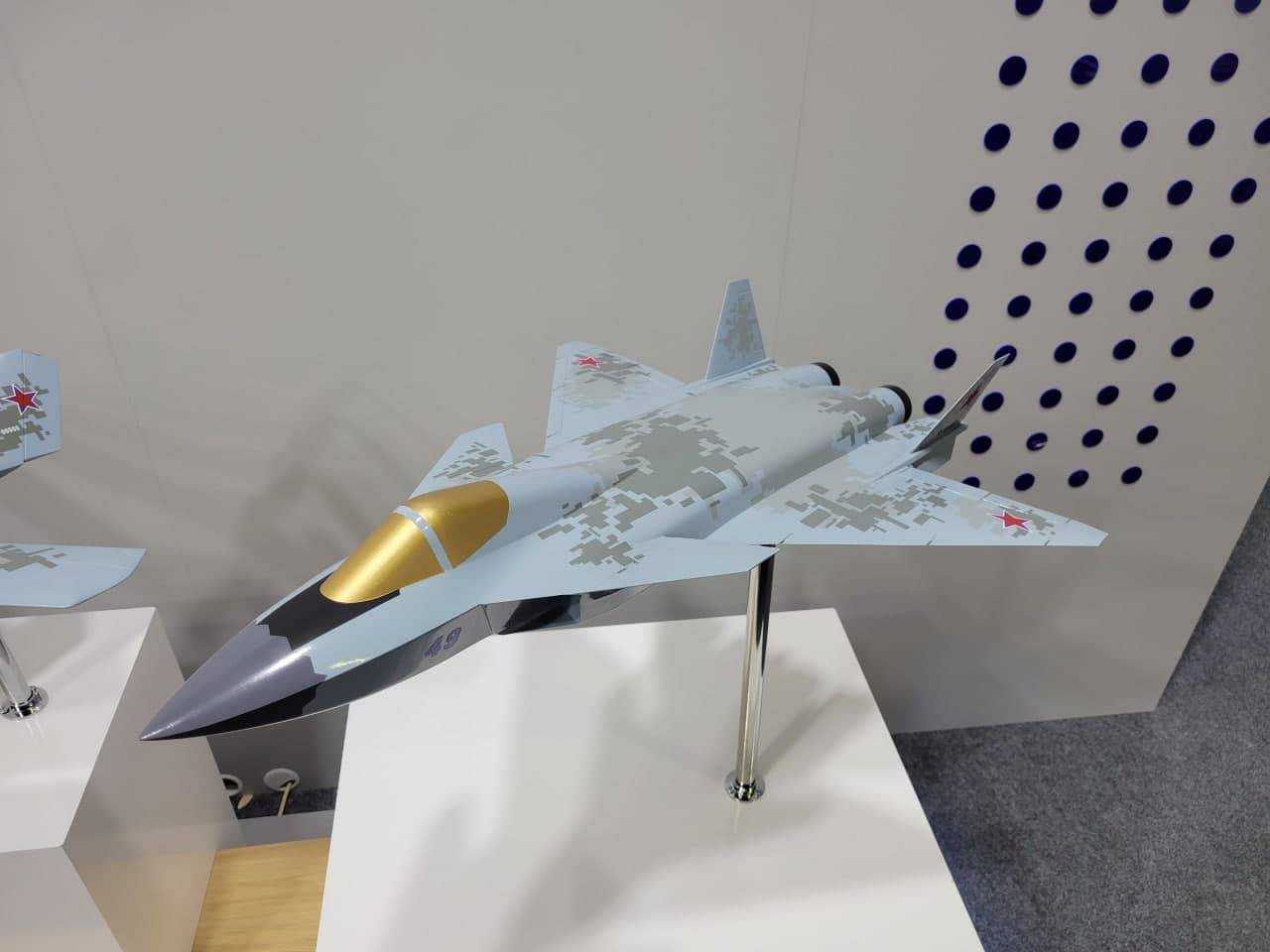
The model of the aircraft, prepared for MAKS-2021, shows the possible appearance of the future carrier-based aircraft. We offer a glider with characteristic smooth and angular contours, built according to the "duck" scheme. Unlike other aircraft of this type, the wing is located not in the tail, but closer to the central part of the fuselage.

Provides a front horizontal tail of medium size and a swept wing with developed mechanization on both edges. The tail section is formed by two protruding engine compartments with a short beam between them, as well as small planes on which the collapsed keels and lower ridges are fixed.


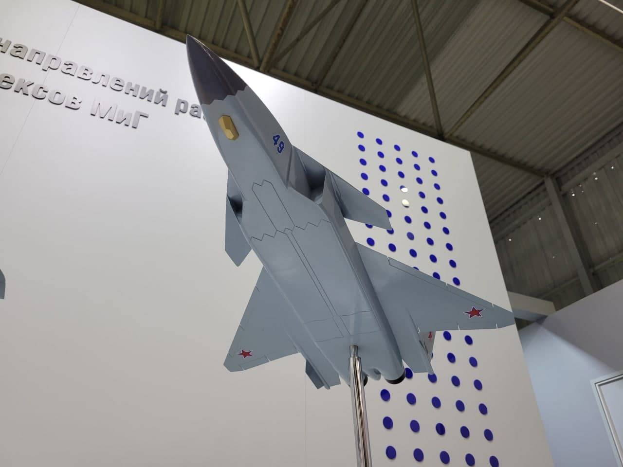
On the flat bottom of the model, three hatches of the chassis niches are visible, as well as two large doors of the cargo compartments. The total length of the compartments can reach one third of the length of the aircraft; the transverse dimension is slightly less than the width of the fuselage. You can also assume the fundamental possibility of transportation weapons under the wing on removable pylons.

The power plant includes two turbojet engines of an unknown model. Perhaps, the project uses engines with a controlled thrust vector, which will give super-maneuverability - one of the hallmarks of the 5th generation. It is curious that the layout has no signs of a vertical takeoff aircraft.

Lead and follower


The layout shows that the new MiG will receive a bow radar station, probably with AFAR. Also noticeable is the ventral optical-location station with a characteristic faceted fairing. Possibly all-round visibility will be provided. Taking into account the requirements for the 5th generation, the use of advanced radio-electronic equipment for communication, data processing and control can be expected. An onboard defense system is also needed.

The lantern of the layout indicates the use of a "short" single cab. Accordingly, all the tasks of piloting, fighting, etc. one pilot will have to decide. At the same time, the fighter is planned to be used in conjunction with a controlled UAV - which will expand the range of tasks assigned to the pilot. As a result, there are special requirements for the on-board equipment of the aircraft, which must perform part of the work and unload the pilot.


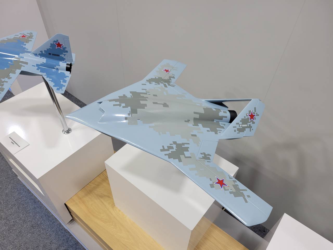
UAV for use with a new fighter

Obviously, the "faithful slave" UAV will receive the most automated control system capable of independently performing a flight, solving combat and other tasks, and also reacting to some changes in the situation. At the same time, the leading aircraft also requires advanced computing facilities and software. The use of artificial intelligence, which helps the pilot in all situations and tasks, looks quite likely.

It should be recalled that artificial intelligence and "faithful followers" are actively developing, but they have not yet reached full use in combat aviation. However, in our country, a complex is already being developed in the form of a Su-57 fighter and an Okhotnik UAV. The developments in this project can also find application in the aircraft complex from RAC MiG.

Development prospects


Reportedly, the MiG carrier-based fighter project is still in its earliest stages. It is not known whether it will be possible to move to new stages and build a prototype in the coming years. So far, both positive and negative scenarios can be considered with equal probability.

It is obvious that the fate of all new projects of RSK MiG, shown in the form of mock-ups at the recent show, directly depends on the plans of the customer, represented by the Russian Ministry of Defense. If our command plans to develop carrier-based aircraft in the medium and long term, the project or projects can receive the necessary support. Thanks to this, a new aircraft or even a whole complex with a manned and unmanned vehicle will be able to appear.


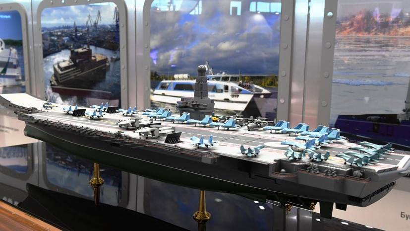
"Manatee" - one of the latest developments in the field of aircraft carriers

Developing new technology will not be quick or easy. The media reported that the MiG corporation may build an experimental aircraft of a new type over the next few years. This means that even with a positive development of events, flight tests will begin only by the middle of the decade. Given the complexity of the project, we can expect the series to be deployed only in the first half of the thirties - if not later.

The future of the proposed UAV is directly related to the fighter. Self-development of such a machine for inclusion in the existing fleet of deck aircraft hardly makes sense. It must be carried out only in conjunction with a 5th generation fighter. With the successful completion of two projects, the Navy will have a unique complex with the widest capabilities, corresponding to the newest and most relevant trends in the development of combat aviation.

It should be borne in mind that the prospects for ship projects of RSK MiG and other aircraft building organizations directly depend on plans for the development of aircraft carrier fleet... The issue of building a new aircraft carrier has been discussed for many years, and there are even corresponding plans. However, their implementation is constantly shifting to the right, which also affects the prospects for the aviation sector.

Operations and orders


So far, new samples of carrier-based aircraft from RAC "MiG" exist only in the form of preliminary developments and exhibition models. The prospects of these projects are still in question and are directly related to the plans of the Ministry of Defense for the development of the fleet. What decisions and when will be made in this context is unknown. So far, only the most general plans and possible dates have been announced.

However, new projects from RSK MiG will have positive consequences regardless of the decision of the military department. First of all, they will help the corporation maintain competencies in the development of modern combat aircraft, as well as contribute to the development of new ideas and technologies for it. In addition, the groundwork for future projects will be created. And if the Ministry of Defense orders a new carrier-based aircraft or UAV, the industry will be ready to fulfill such an order in full and in the shortest possible time.
134 comments
Information
Dear reader, to leave comments on the publication, you must sign in.
  1. +15
    31 August 2021 18: 15
    Maybe first deal with the carrier of carrier-based aircraft? And will we postpone the cuts with aircraft for later? Plans are huge. Then someone will have new dachas near London negative
    1. +7
      31 August 2021 18: 24
      "I AM
      our plans
      I love a lot
      scope
      fathoms steps. "
      It would be nice for a start to see all these layouts in hardware, then there would be a substantive conversation ...
      1. +4
        31 August 2021 18: 30
        Dear SERGE ant. As for the plans, I had in mind a little different. In the sense of money laundering.
        1. -1
          1 September 2021 18: 05
          Quote: bandabas
          Dear SERGE ant. As for the plans, I had in mind a little different. In the sense of money laundering.

          =========
          "Sawing the babal" .... "Money laundering" .... "Summer cottages near London" .... Like this one couch whine already sick of it !!!
          We have wonderful machines: Su-30 and Su-35 .... But alas! Their modernization potential is almost exhausted! It is difficult to think of something better (within the framework of this design). The MiG-35 is a temporary measure: it is clear that the design has already exhausted itself.
          Su-57 is a "piece" machine - they do not plan to build many of them - too expensive ...
          Su-75 is still only in the form of a demonstration sample, and who knows how else its fate will develop (God forbid, to be successful!) .....
          Meanwhile many other countries are already developing promising machines - for the FUTURE!
          We will stand and wait .... Or still lead promising developments? MiG-sheep are developing and whether it will be clean deck or universal - suitable for the land version? It's not clear yet! Kirill Ryabov does not give an answer to this question (no one knows this yet ...). What will come of it - we'll see!
          1. The comment was deleted.
    2. +8
      31 August 2021 18: 28
      Again cuts ... The state, represented by the Ministry of Defense, sets a task. An estimate is made, moreover, rigidly, on the verge of reality. And if someone did the impossible - and the order was fulfilled and the dacha was built, then this is already the problem of the RSK MiG and not the Ministry of Defense. But if there is a cost overrun, then for this there are specially trained people who will dig the earth with their nose for an asterisk. In general, it is not for us to decide and this is not our business, unless of course you are from the tax or prosecutor's office.
      1. +1
        1 September 2021 10: 25
        You are seriously thinking. that the money is sawed by the performers, but the officials in the Ministry of Defense do not receive their share?
        1. +2
          1 September 2021 21: 27
          Do you have any facts, or is it just a joke from a blakit couch?)
    3. -2
      1 September 2021 06: 41
      creation of the next 5th generation carrier-based fighter

      And the recently announced Shakhimat is no longer rolling with fanfare? To adapt it to the deck, or better - to make a vertical takeoff, won't it work out of it?
      1. +4
        1 September 2021 08: 42
        He has a shortened takeoff. It is impossible to remake it for a vertical one. It's easier to create a new plane.
        1. -3
          1 September 2021 09: 01
          Quote: Roma-1977
          It is impossible to remake it for a vertical one.

          Do not put a fan in front?
          1. +3
            1 September 2021 09: 04
            Even if you remove the in-fuselage compartments for weapons, it will still not fit. Such alteration of the airframe will be required, which is simpler than a new one.
    4. 0
      1 October 2021 10: 14
      Yes, to begin with, do the layouts of the decks - and then the layouts of the carrier-based aircraft!
  2. +4
    31 August 2021 18: 30
    And if the Ministry of Defense orders a new carrier-based aircraft or UAV, the industry will be ready to fulfill such an order in full and in the shortest possible time.

    To begin with, I would like to "execute" the GPV.
    Our industry and Borisov know how to boast.
    Deputy Prime Minister Yuri Borisov said that the Ministry of Defense will receive four Su-2021 fighters in 57
    belay
    Can the SU-57 be put on the wing first?
    1. +2
      31 August 2021 18: 44
      How does work in MiG affect work in Sukhoi?
      1. +4
        31 August 2021 18: 50
        Quote: Barberry25
        How does work in MiG affect work in Sukhoi?


        https://uacrussia.ru/ru/
        UAC is a shareholder of the following companies:
        PJSC "Company" Sukhoi "- 81,1%
        JSC Russian Aircraft Corporation "MiG" - 100%
        well and so on

        the budget is not rubber

        MIG-41 was still there.
        1. +5
          31 August 2021 18: 56
          and? in any case, we will need a ship's plane, so it's easier to contract Migars, as having real experience, than to load dry ones, which are already sewn up with the modernization of the Su-30, Su-34, Su-35, the launch of the C-70, Su -57 and the development of the Su-75. Let them work, otherwise they will degrade, which in the end will lead to the fact that they will have to be eliminated, which will be the beginning of the end.
          1. +2
            31 August 2021 19: 47
            Quote: Barberry25
            and?

            Bolivar cannot carry double - O. Henry "The Roads We Choose"
            and we don't even have TWO, but hell knows how much. Borisov and Slyusar, Serdyukov and Krivoruchko. ugh mlyn, I meant: SU-35, SU-30xxx, SU-34, MIG-35, PAK FA, PAK DA, TU-160, TU-22, etc. I have not yet reached ekranoplanes

            we will need a ship's plane anyway, so it's easier to order migars

            hmmm. to receive at least one aircraft carrier ... at least the timing of its commissioning
            Quote: Barberry25
            otherwise they will degrade, which will eventually lead to the need to eliminate them, which will be the beginning of the end.

            The USSR ended badly. Warehouses were filled up with tanks, planes, there was nothing to eat, but the defense industry was chic
            1. +3
              31 August 2021 23: 44
              Kuzyu is being made, UDC on which large-tonnage construction is being run in are laid ... and the development and testing of aircraft is not a quick thing, just by the time the first aircraft carrier is received, it is better to have ready-made vehicles than to wait for them for another 10 years
              1. -2
                1 September 2021 10: 06
                nonsense.
                - Kuzyu has not been done yet
                -dock, where to build an aircraft carrier, and is not expected.
                - even the very concept and answer do we need it: no, and it is unlikely to be during our lifetime and this government
                10 years old is when the 1st (SU-33). And when it is clear, they will cope in 3.
                / well, that's my opinion.
                I'm not a specialist: but all this (a new one from a moment - like another PR, like "Platform-O": billions in pockets, the result is zero
                1. -2
                  1 September 2021 10: 38
                  laughing 1) Kuzyu will be made 2) how docks are built, not to mention the Gulf, which can build aircraft-carrying cruisers
                  3) the concept has been discussed on the site more than once; 4) they won't even upgrade over the years, let alone a full-fledged plane ..
            2. +6
              31 August 2021 23: 44
              The USSR ended badly that its leaders got sick, and not because "the shelves were empty"
              1. 0
                1 September 2021 09: 50
                Quote: Barberry25
                The USSR ended badly that its leaders got sick, and not because "the shelves were empty"

                Why invent?
                I graduated from school in 1983. I remember everything perfectly.
                And in North Korea, what's wrong? Who's got it? for years already?
              2. 0
                3 September 2021 15: 54
                it is an interconnected process. You can say - "The USSR ended badly, because the shelves were empty, because the leadership went bad"
                Man-made scarcity is such a thing ...
            3. +1
              1 September 2021 03: 22
              Quote: ja-ja-vw
              Warehouses were filled up with tanks, planes, there was nothing to eat

              The idiocy of this comment is evident. A person who thinks that tanks and planes are gathering dust "in warehouses" and imagines that they were starving in the late USSR, has a very low level of mental development.
              1. -1
                1 September 2021 15: 08
                Maybe in Moscow and Leningrad in the 80s there was a meat assortment in stores and not bad. But ours is bad. From "meat" on free sale - only pasty liverwort. In a furniture store - an appointment for the purchase of a section for 2 years in advance. In the shoe - only rubber boots.
                1. -3
                  1 September 2021 15: 50
                  Quote: OCefir
                  From "meat" on free sale - only pasty liverwort.

                  Was there no meat on the market and in the canteens?

                  Quote: OCefir
                  In a furniture store - an appointment for the purchase of a section for 2 years in advance. In the shoe - only rubber boots.
                  What a lie, leather shoes, touring boots, gnarled boots have always been. Yes, clumsy, but always. And something Czech or Yugov was thrown out periodically.
            4. -3
              1 September 2021 21: 29
              All this is a lie, one naked lie and it turns out that whoever is pushing this lie is an impudent liar.
            5. -1
              29 November 2021 13: 52
              ja-ja-vw \ Again the USSR is hungry .. In the Russian Federation were born and grandfather told about the saints of the nineties at night?
          2. -2
            1 September 2021 03: 25
            Quote: Barberry25
            so it's easier to order migars like they have real experience

            It may be simpler, but it would not work out worse, if only because the Sukhovites have more experience in the aircraft carrier business. Su-25 and 27 versus one MiG-29.
            1. +1
              1 September 2021 10: 36
              more experience, but not where it is needed .. in the end they will do for a long time, without a guarantee of success +
              this will put a cross on the MiG design bureau, which will lead to the disappearance of competition and the degradation of the industry as such ... an example of Kamov to help
  3. +7
    31 August 2021 18: 42
    how we are all developing interestingly:
    - a lot of attention to carrier-based aircraft, but no clarity even with a single aircraft carrier;
    - UDCs are laid down, but there are no actual helicopters for them, even on paper.
    as Victor Stepanych said - "this has never happened, and now - again"
    1. +1
      1 September 2021 07: 53
      But what is the conclusion from this? To have carrier-based aircraft on time, you have to start now.
  4. +7
    31 August 2021 19: 18
    MiG-35 series two. To be honest, it's not even funny anymore.
  5. +2
    31 August 2021 19: 59
    IMHO the task facing the MiG causes some skepticism. Of course, I'm not a specialist in aviation, and even more so in carrier-based aviation, everything written below is purely "brainstorming".
    1) MiG competencies in stealth are inferior to Sukhov ones, MiG designs are quite different from dry ones. MiG competencies in actual carrier-based aviation are also, in my opinion, inferior to SUkhom.
    2) The MIG's ability to create a single-engine deck vehicle raises a certain amount of doubt, since the actual designs have already been for quite a long time from this design bureau - twin-engine ones, for slightly different tasks and requirements. I did not observe actual projects on VTOL aircraft of the MiGs. The MiG 1.44 was not a twin-engine VTOL aircraft - acc. in general, for the MiG design bureau as a whole, the task will be extremely atypical.
    3) Considering the apparently more modest in size (relative to American projects) projects of our promising aircraft carriers - the question of a twin-engine aircraft, and even with a slave-UAV, also causes skepticism. The seats will be decently occupied, but the shock capabilities in such a set will obviously be inferior to the American ones.
    4) At the moment, even the issue of building an aircraft carrier in the distant future has not been resolved. All the more so with the number of such aircraft carriers. Apparently, even if he decides, we will hardly go beyond 2-3 ships, purely for economic reasons. In view of this, investing significant resources in design bureaus, for which this task is, to put it mildly, atypical - in order to end up with a relatively small batch of aircraft - while there is a SUKh with more relevant solutions and competencies.
    IMHO specifically in this direction, the MiG does not shine. PAK DP will order them and work guys ..
  6. +7
    31 August 2021 20: 15
    How much can you do?
    Either noodles about MIG 41, then SU ​​75 - like a ready-made deckboat, then after MAKS they again pull on a small model - a 5th generation deckboat ...

    If they want to support MIL - give money so that people don't run away, write honestly how much, and let the FSB catch new apartments from the children of the bosses ...
  7. Eug
    +3
    31 August 2021 21: 33
    The promising deck boat is aerodynamically very close to the MiG-1.4 (x), the scheme of the late twentieth century. Good or bad - I do not know, but it seems that "invisibility" has ceased to be fetishized, this is also indicated by the appearance of the "bucket" from Sukhoi, and the promising (?) Deck ship with PGO from Mikoyan. The only one of the presented models that I like is the LBS (in the unrepresented single version). There is no data on him, but it looks like he is in the "weight category" of the MiG-21 and F - 5E.
  8. 0
    1 September 2021 07: 38
    Again layouts. Ryabov again ... request
  9. 0
    1 September 2021 09: 06
    I hope that the times of "three identical" tanks, "two identical helicopters (or even three)", "Three similar in size and performance characteristics of fighters" have passed or are passing. Chose a heavy fighter - make it! We need a co-pilot there - add a cockpit !, you need a long range and you don't need excessive maneuverability - add a segment with a tank! There is not enough radar coverage - make an AWACS of medium-small sizes. We need an LMFI - take one turbojet engine - and make it on its basis.
  10. 0
    1 September 2021 13: 09
    I would not like to be a prophet, but I am afraid that it will be again "New model of carrier-based fighter from RSK MiG for new models of aircraft carriers".
    1. 0
      1 September 2021 14: 06
      By and large, the MiG35 will suit the deck calmly. We need fresh RD-XX and avionics. Why is there ck = upset stealth plane? And, of course, you need a deck.
  11. 0
    1 September 2021 23: 20
    I'm not an expert in aircraft layout, but, in my opinion, the concept is too archaic. It seems that this is an updated MiG 1.44.

    It is clear that the developments on this machine were the pinnacle of domestic science and technology in the 90s, but it was a ground forces machine, primarily to replace the Su-27 and MiG-31. Why, suddenly, this project turns out to be good for the deck?
    1. 0
      2 September 2021 12: 19
      Quote: abc_alex
      developments on this machine were in the 90s the pinnacle of domestic science and technology,

      Today, the pinnacle of technology is the use of microwave heating of the exhaust plasma jet to increase the jet thrust of a turbojet engine. This was reported 6 years ago by Gera Ivanov in the comments to the video https://www.youtube.com/watch?v=4lGkKFh8pwk:
      @Sergey Filippov The very principle of jet thrust is the last century. One wrote to me in the combustion chamber they install a magnetron to raise the thrust or something. that is, we need new devices like UFOs, I do not believe that we do not have such equipment. the Americans definitely have it.
      1. +1
        13 January 2022 19: 54
        - It's simple "nonsense in vegetable oil". Fake.
  12. 0
    2 September 2021 04: 09
    Korls need a drone - a reconnaissance tanker, a tanker and a missile carrier, air-to-air - an air-ship, a bomb carrier for submarines.
    1. +1
      2 September 2021 12: 14
      Quote: Lepsik
      Korls need a drone - a reconnaissance tanker, a tanker and a missile carrier, air-to-air - an air-ship, a bomb carrier for submarines.

      To be based on the deck of a ship, an aircraft must be capable of short take-off and vertical landing. One of the options is to use a vertical takeoff and landing aircraft (VTOL) such as a flying saucer with the exhaust of a turbojet engine (TRD) upward and then sideways to spin an annular disc-rotor (like a spinner) equipped with retractable blades to create lift during vertical takeoff / landing ..


      In the second figure - VTOL aircraft with the annular rotor removed.
      To spin up the rotor disk, an annular blade ring is installed inside it, with the possibility of blowing exhaust from the turbojet engine rotary nozzle. Before vertical takeoff, the rotary nozzle of the turbojet engine is moved to a vertical position, the exhaust port is opened on the upper plane, folding two curtains in the form of a house. After vertical take-off, the rotary nozzle is transferred to a horizontal position, and the exhaust opening is closed on the upper plane of the fuselage skin, moving the two shutters to a horizontal position with a hydraulic cylinder. VTOL control in hover mode - by regulating the flow rates of four air bleed from the second turbojet engine circuit directed vertically downward through four air bleed pipelines of the turbojet engine second circuit are not shown in the figure.
      1. 0
        3 September 2021 23: 40
        Mr. Gridasov? Is it you?
  13. +1
    4 September 2021 12: 58
    It's a pity KB, there were good planes.
    1. +1
      6 September 2021 18: 54
      And why the turbojet engine is on the bottom, it would be more logical to install it from above, so foreign objects will be drawn into the air intake, but otherwise this is probably the most realistic scheme for a VTOL aircraft
      1. +1
        9 September 2021 13: 26
        Quote: agond
        Why is the turbojet engine at the bottom?

        The turbojet engine stands at the bottom, since the exhaust upward and then to the side will provide additional lifting force due to the higher speed of the exhaust flow around the upper surface of the disc-shaped annular wing compared to the flow rate of the air sucked into the air intake flowing around the lower surface of the disc-shaped wing. The Su-75 Checkmate has a single engine with an air intake, also located at the bottom of the fuselage.
        Many drones, such as the RQ-4 Global Hawk, have a single turbojet engine (turbojet engine) overhead. Such an upper location of the turbojet engine at high angles of attack can lead to unstable operation, surge of the turbojet engine.
        To increase the reliability of deck-based aircraft, it is advisable to use twin-engine short-take-off and vertical landing aircraft (VTOL), for example, such a twin-engine heavy VTOL aircraft with an upper turbojet engine inlets and turbojet exhaust downward and then sideways:


        In the second figure - VTOL aircraft with the annular rotor removed. Inside the disc-shaped annular wing on this VTOL aircraft can be placed a circular AESA circular view with a synthetic aperture.
        1. +1
          13 January 2022 19: 57
          - Make a normal aircraft carrier with four steam catapults, "a la Nimitz" and not "punch brains" with empty searchlights ...
  14. 0
    8 September 2021 13: 10
    But what about the new classmate "Shakhimat" ?! Why two light fighters? In general, it's a shame for the MiG with its models, the famous company seems to really be bent. The layout of the shakhimat will be more
  15. 0
    13 September 2021 16: 38
    It remains only to find a deck for this fighter ...
    1. +1
      14 September 2021 08: 48
      Quote: Svetlana
      Quote: agond
      Why is the turbojet engine at the bottom?

      .

      In the diagram of VTOL aircraft you have given, we see a lifting multi-blade propeller driven by an internal blade row, I think this is wrong,
      1 the diameter of the propeller turns out to be too large and the peripheral speed of the propeller blades will be greater than the speed of sound, and there are many blades, there will be a lot of noise and the efficiency will drop
      2 this screw must have a large inner hole where the peripheral speed will be too high for conventional bearings, in general such a screw is difficult to manufacture
      3 the peripheral speed of the inner blade row will be too low for rotation from the jet of gases of the turbojet engine
      Hack and predictor Aviator
      you need a multi-blade lifting rotor of a reduced diameter with an outer blade crown, the VTOL aircraft itself will have a classic look - the cockpit in the front, in the center of the aircraft there is a multi-blade propeller in the ring, on the sides of the wing ring, a turbojet engine with a rotary nozzle is located above the propeller, which is needed to remove gases to the blade the crown during takeoff and landing, the rest of the time the engine is used as a sustainer and the plane flies in the usual way due to the lift of the wings
      1. 0
        15 September 2021 21: 58
        Quote: agond
        the diameter of the propeller is too large and the peripheral speed of the propeller blades will be greater than the speed of sound

        There is no supersonic speed at the tips of the blades. The maximum blade tip speed is 97 m / s (349 km / h). For comparison, Antonio Pizzonia at Monza in 2004 on a Williams FW26 chassis with a BMW engine in the Formula 1 race showed a speed of 369,9 km / h. And another Williams, FW38, in Mexico City 2016 with a Mercedes engine driven by Valtteri Bottas, also in racing mode, reached a speed of 372,54 km / h.
        Estimated parameters of the disc:
        1. +1
          16 September 2021 08: 21
          Quote: Svetlana
          No supersonic speed at the tips of the blades

          Let it be so, but an annular rail with a diameter ten times larger than that of a conventional shaft is required, therefore friction losses in the bearings will be higher, and since you want to make the subsonic speed of the ends of the lifting rotor blades, the blade ring on the annular rail will have insufficient speed for effective work in a jet of gases turbojet engine
          1. 0
            16 September 2021 13: 22
            Quote: agond
            the blade ring on the annular rail will have insufficient speed for efficient operation in the turbojet engine gas jet

            Turbine stages are speed stages and pressure stages. In speed stages, the vane speed is important, ideally the vane speed should be half the flow rate. But in the pressure stage, the speed of the blade is not so important, in it the pressure drop of the flow above and below the blade is triggered, which leads to the moment of force required to drive the rotor with blades in rotation.
            In a disc, the blade ring is a turbine pressure stage.
            The exhaust flow of the turbojet engine, flowing around the profiled blade of the rotor blade rim of the disc, leads to a transverse force (its nature is the same as the lifting force of an airplane wing), which arises due to the difference in flow pressures above and below the profiled blade. Moreover, the magnitude of the lift is proportional to the square of the speed of the exhaust flow of the turbojet engine running on the blade, and the transverse speed of the rotor blade itself is directed perpendicular to the oncoming exhaust flow and does not participate in the formula for calculating the transverse (ie, "lift") force acting on the rotor blade.
            The cutaway blade has a crescent shape,
            The shape of the crescent allows the rotor blade to change the vector of the exhaust flow of the turbojet engine by 90 degrees and obtain the reactive force that drives the rotor disc with the blade ring and the blades extended by centrifugal force into rotation.
            To increase the efficiency of the blade row in the exhaust gas jet, it is possible to use a turbine speed stage with a two-row blade disk on the disc rotor, and / or direct the turbojet engine exhaust not only downwards, but also slightly sideways, along a tangent to the annular rail with a rotary nozzle. In this case, the crescent-shaped rotor blades will no longer rotate the exhaust stream by 90 degrees. and by 180 degrees, which will increase the force acting on the rotor blades from the side of the exhaust flow of the turbojet engine.
            On the impeller of an active single-stage turbine inside the disc rotor, the jet from the turbojet engine nozzle will rotate 180 degrees and give its impulse to the turbine blade. The force impulse will be transmitted even when the disc rotor is completely braked. See https://www.youtube.com/watch?v=yCr1SRQ_vXY
            1. +1
              20 September 2021 14: 08
              [quote = Svetlana] In a disc, the blade ring is a turbine pressure stage. [/ quote]
              [quote = agond] and since you want to make the subsonic speed of the ends of the blades of the lifting rotor, the blade ring on the annular rail will have insufficient speed for efficient operation in the gas jet of the turbojet engine [/ quot]
              I was wrong, the peripheral speed of the outer blade row will always be two to three times higher than that of the inner one, however, with the same sizes of multi-blade screws
              1 the centrifugal force tending to break the outer rim will be ten times higher than if it were the inner
              2 the outer rim will contain two to three times as many blades,
              3 the outer rim screw will be one and a half times heavier than the inner rim screw
              4 a heavier propeller with a significant proportion of mass concentrated on the circumference (ring with blades) will create unnecessary gyroscopic moment.
              From what has been said, it follows that multi-blade lifting screws of large diameter 10 meters or more with an external blade rim are most likely unsuitable, and the construction of a VTOL aircraft that looks like a UFO is unnecessary.
              Conclusion - VTOL aircraft should be built according to the usual architecture, that is, VTOL aircraft based on
              1 relatively small multi-blade lifting rotor with a diameter of 3-4 m mounted on an axis in the area of ​​the aircraft's center of gravity,
              2 the ends of the propeller blades are fixed inside the blade row, the rotation of the propeller occurs from the blowing of the blades of the row of streak gases from the turbojet engine
              3 turbojet engine is located above the lifting screw, has a deflected nozzle for blowing the blade row
              1. +1
                20 September 2021 22: 21
                Quote: agond
                the ends of the propeller blades are fixed inside the blade row

                When the lifting blades are located inside the blade ring of the working turbine blades:
                - the total mass of the turbine blade row (made of heavier elements of the periodic table) will probably be higher than the total mass of the lifting blades, which will lead to a heavier structure.
                - the total area of ​​the lifting blades will be insufficient to create a lifting force due to the limited space inside the VTOL fuselage.
                - a small multi-blade lifting propeller with a diameter of 3-4 m mounted on an axis in the area of ​​the aircraft's center of gravity will "eat up" the useful volume inside the fuselage
                VTOL aircraft. There will not be enough space for the payload inside the fuselage.

                To reduce the mass of the disk, the total cross-sectional area of ​​the turbine blade row of rotor blades blown by the exhaust flow of the turbojet engine should be less than the total area of ​​the blades that create vertical thrust.
                The rotor blades blown by the exhaust stream of the turbojet engine operate in more severe conditions of the aggressive action of the high temperature of the hot jet of exhaust gas from the turbojet engine.
                Therefore, the rotor blades must be made of heavy metals with a high melting point. High-temperature ceramics (aluminum oxide, for example) are still used to make only a thin surface layer applied to the surface of the rotor blades of turbojet gas turbines.
                The lifting blades, which create vertical thrust, are made of lightweight composites that can withstand much lower temperatures than the exhaust temperature of the turbojet engine.
                The specific gravity of the turbine blade ring (i.e., the mass per unit area of ​​the crown) is greater than the specific gravity of the crown of the lifting blades.
                In a disc, the area of ​​32 pieces of rectangular blades is 136m2 (each blade has dimensions of 1,33m * 3,19m), and the rotation speed of the blade ends is 97m / s (the blade ends are located at a radius of 15m).
                For comparison, the MI-26 helicopter:
                8 blades
                16 m blade length
                220 m/s tip speed
                0,835 m blade chord
                375,000 kg blade weight
                56,000 tons maximum takeoff weight
                106,880 m2 total blade area
                523,952 kg/m2 specific blade load
                28,069 kg/m2 blade specific gravity
                Those. the blades of a disc-plane work in less severe conditions, in comparison with the blades of the MI-26.
                With a comparable total area of ​​the disc and MI-26 blades and a comparable total lifting force of the blades, 32 disc blades operate at 4,8 times less centrifugal acceleration than the MI-26 blades.
                The total mass of 32 pieces of the disc blades is 4 tons, (at a blade tip speed of 97 m / s), taking into account the specific weight of the blade 28 kg / m2 as in MI-26.
                The total weight of 8 pieces of MI-26 blades is 3 tons (at a blade tip speed of 220 m / s), taking into account the specific weight of the blade 28 kg / m2.
                The total vertical lifting force of 8 pieces of MI-26 blades is 56 tons.
                The total vertical lift of 32 pieces of disc blades is 94 tons.
                When the lifting blades are drawn into the rotor, there is a significant rotational area of ​​the upper surface of the rotor disk (above the location of the blades drawn into the rotor). When the rotor rotates, the lifting force of the extended blades (94tns) is summed up with approximately the same lifting force (89,7tns) arising due to the rotation of the air over the rotor disk (since when the rotor rotates, the air above the rotor is entrained in rotation by the upper surface of the rotor and above a vertical column of air rotating like in a tornado with a reduced pressure inside it appears by a disk-jet).
                The gyroscopic moment during takeoff and landing will ensure the stability of the plane of rotation of the blades in the horizontal plane, will not allow the disc to tip over and whip the blades along the horizontal deck.
              2. +1
                21 September 2021 09: 51
                Quote: agond
                VTOL aircraft must be built according to the usual architecture

                Can the usual architecture of the Focke-Wulf Fw 189 Uhu ("PaMa") aircraft be used for VTOL aircraft?

                A multi-blade propeller in the center of gravity between the two fuselages is blown with exhaust jets from the turbojet engine's rotary nozzles. After takeoff, like that of Osprey (mv-22 osprey), the multi-blade propeller is turned on two axes from horizontal to vertical position and continues to be blown with exhaust jets from turbojet rotary nozzles. Osprey, there is no transverse shaft summing the torques of the turbojet engine
                1. +1
                  21 September 2021 10: 31
                  Quote: Svetlana
                  Can the usual architecture of the Focke-Wulf Fw 189 Uhu ("PaMa") aircraft be used for VTOL aircraft?

                  It cannot be, but it is necessary to build exactly according to such a scheme, at least it is necessary to start with it, two turbojet engines rotate one multi-blade lifting screw, it is believed that a VTOL aircraft should have one engine, and, say, two or three greatly reduce reliability, but in In this scheme, if one fails, the second will rotate the propeller, which will allow the plane to land.
                  About
                  - "The rotor blades blown by the exhaust stream of the turbojet engine operate in more severe conditions of the aggressive action of the high temperature of the hot jet of exhaust gas from the turbojet engine."
                  , everything is not so bad, since in your circuit, the turbojet engine can blow only 10-15% of the rim blades with a stream of gases at a time and therefore they are not threatened with overheating and therefore you can discharge compressed air directly from the turbojet engine compressor into a separate combustion chamber located next to the blade row and in this chamber it is POSSIBLE to create a combustion temperature HIGHER than in any other turbojet engines and thereby raise the unit's efficiency.
                  1. 0
                    24 September 2021 23: 41
                    Quote: agond
                    it is believed that VTOL aircraft should have one engine, and let's say two or three greatly reduce reliability,

                    For reliability, you can use 1 engine located near the center of gravity of a VTOL aircraft of the "flying wing" type:

                    In this scheme, the lifting rotor after takeoff is deployed together with the turbojet engine from a horizontal position to a vertical one.
                    1. +1
                      26 September 2021 19: 59
                      Quote: Svetlana
                      For reliability, you can use 1 engine located near the center of gravity of a VTOL aircraft of the "flying wing" type:

                      Two or more engines are critical for an aircraft of the Yak-141 type, where the failure of any of the three engines leads to imbalance and an accident (the total lift is displaced from the price of the aircraft's gravity), in your scheme the lift is created by a multi-blade propeller, so if, for example, as in helicopters have two turbojet engines, then the failure of one will only lead to a decrease in lift without shifting the point of its application, and if the reserve of its power allows it, then you can safely land the plane
                      Turning the turbojet engine greatly complicates the design, because in addition to everything else, the center of gravity of the aircraft is also shifted back, it is probably easier to deflect the gas stream, and not turn the engine, and place the engine itself somewhere above the axis of rotation of the lifting screw, so that the rotary nozzle would be on the blade crown
                      1. 0
                        27 September 2021 12: 42
                        Quote: agond
                        Turning the turbojet engine greatly complicates the design
                        Variant VTOL type "flying wing" without turning the turbojet engine. In this version, a turbojet engine with a rotary nozzle is used, as in the Yak-141:
                        The lifting fan consists of two counter-rotating blades to reduce the lateral reactive force from the exhaust that has passed through the blades of the lifting fan. And by the way, such a scheme can be amphibious, i.e. capable of taking off from the water, not just from the deck.
                      2. 0
                        27 September 2021 23: 44
                        Quote: agond
                        if, for example, as in helicopters, you have two turbojet engines, then the failure of one will only lead to a decrease in lift without shifting the point of its application, and if the reserve of its power allows it, you can land the plane without an accident
                        You are right, for reliability it is better to have 2 turbojet engines, despite the fact that this increases the cost of the plane. To reduce the visibility of VTOL aircraft on radar screens, these 2 turbojet engines with rotary nozzles can be hidden in the fuselage. During vertical take-off, the left turbojet engine rotates with its exhaust the blade ring of the lower lifting rotor, and the right turbojet engine turns with its exhaust the blade ring of the upper lifting rotor in the opposite direction. The vane of the upper lifting screw directs the exhaust of the right turbojet engine back and then down. The blade crown of the lower lift screw directs the exhaust of the left turbojet engine back and then down. For this, during takeoff, the rotary nozzle of the right turbojet engine is turned slightly up and to the left, and the rotary nozzle of the left turbojet engine is turned slightly down and to the right. Moreover, the nozzles at the outlet are given an oval (almost rectangular) shape, which also reduces the visibility of VTOL aircraft on radar screens.
                      3. 0
                        28 September 2021 15: 19
                        In the last diagram (it would be nice to number the diagrams, so that there would be no confusion), the turbojet engines are located on the sides, this has disadvantages
                        1 if the blades of the blade ring are located in the plane of rotation of the multi-blade lifting screw, then for their shoes it is required to remove gas from the turbojet engine with two turns, that is, to the left or to the right and then down, this reduces the kinetic energy of the engine jet, the efficiency decreases and, at the same time, the gas channel lengthens and the engine moves forward with its weight
                        2 since both engines and the cockpit are in front of the propeller rotation axis, the center of gravity will shift forward and it will not coincide with the center of its rotation, and there is nothing to compensate for this displacement, there is no equipment in the plane that could be shoved into the tail
                        Conclusion, it is best to put two turbojet engines close to the top, to the left of the axis of rotation of the propeller, then their weight compensates for the weight of the front part.
                        By the way, when a relatively large lifting rotor rotates, a significant torque will be generated that tends to turn the plane in the opposite direction (like a helicopter) and it also needs to be compensated somehow
                      4. +1
                        28 September 2021 20: 08
                        Quote: agond
                        it is best to put two turbojet engines close to the top, to the left of the axis of rotation of the propeller, then their weight compensates for the weight of the front part.
                        By the way, when a relatively large lifting rotor rotates, a significant torque will be generated that tends to turn the plane in the opposite direction (like a helicopter) and it also needs to be compensated somehow

                        In Fig. 8 VTOL aircraft with two turbojet engines, placed close to the left of the axis of rotation of the counter lifting screws. The counter-rotation of the lifting screws compensates for the torque that tends to turn the aircraft in the opposite direction (like in the KA-52 helicopter).
                      5. 0
                        30 September 2021 19: 36
                        It is already better, although it is not clear how to rotate the lower lifting screw (green) between the blade rims of the lower and upper rotor, there will be a large gap, as an option, you can twist the upper one from the gas jet of the turbojet engine, and the lower one with a simple gear transmission from the upper propeller, you will need an orbital reducer of the type as in a screwdriver, Two counter-rotating propellers will be of a smaller diameter than one, and yet vertical take-off and landing are not the main mode of VTOL aircraft, the main mode remains horizontal flight, and here you cannot do without traditional wings,
                      6. +1
                        1 October 2021 00: 31
                        Quote: agond
                        it is not clear how to rotate the lower lifting screw (green) there will be a large gap between the blade rims of the lower and upper screws

                        During vertical takeoff of VTOL aircraft, the shutters of the lifting screws are opened, the swivel nozzles are directed downward onto the drive blade ring of the upper fan. The angles of attack of the blades and driving blades of the lower lifting rotor are opposite to the angles of attack of the blades and driving blades of the upper lifting rotor (i.e., the angles of attack of the blades and driving blades of the lower rotor are equal with a minus sign to the angles of attack of the blades and driving blades of the upper rotor). The exhaust from the turbojet engine rotary nozzles drives the blade ring of the upper fan into rotation, the exhaust flow leaves the plane of the upper screw at an angle of about 45 degrees, then blows and drives the blade ring of the drive blades of the lower lift fan into counter rotation and leaves the plane of the lower screw vertically downward.
                        Quote: agond
                        and here you can't do without traditional wings
                        Yes, wings will be needed for level flight at transonic speeds. The figure shows a VTOL aircraft similar to Northrop_Grumman_B-2_Spirit:
                      7. 0
                        3 October 2021 20: 22
                        Quote: Svetlana
                        The exhaust from the turbojet engine rotary nozzles drives the blade ring of the upper fan into rotation, the exhaust flow leaves the plane of the upper screw at an angle of about 45 degrees, then blows and drives the blade ring of the drive blades of the lower lift fan into counter rotation and leaves the plane of the lower screw vertically downward.

                        This can be done if the "wheels" of the blade rims are placed with a small gap, but it will be difficult to ensure this small gap with a diameter of 10 m, and then about 10% of the rim blades are in contact with the gas jet of the turbojet engine, and the rest simply contact the air that provides them resistance, although there will be a lifting force on the blades, but still one crown only on the return propeller is much simpler than two, so it is better to turn the lower vent by the gearbox from the upper one, by the way, the gearbox can now be found on some turbofan engines of passenger aircraft.
                      8. +1
                        4 October 2021 09: 12
                        Quote: agond
                        but still, one crown only on the return screw is much easier than two
                        You are right, one crown only on the top screw is much easier than two. Some doubt arises in connection with the reliability of orbital (planetary) gearboxes. For example, when testing the Tu-95 engine (it has planetary gearboxes installed on its turbines, which reduce the rotational speed from 8300 rpm to 735 rpm), there was a failure associated with fatigue destruction of the gear wheel.
                        The calculation will show that it is lighter in weight - two drive blades of the upper and lower screws, or one drive blade of the upper screw plus the mass of the orbital gearbox.
                        In this regard, the question arises about the optimal choice of diameters and the number of blades on the upper and lower lifting screws and the optimal ratio of their rotational speeds, since the compensation of the torque of the upper lifting screw can be obtained at different values ​​of the moment of inertia Jн and the rotation frequency Wн of the lower lifting rotor, the main thing is so that the product J * W ^ 2 for the upper lifting rotor with driven blades equals the product Jn * Wn ^ 2 for the lower lifting rotor with driven blades (or without driven blades).
                      9. +1
                        4 October 2021 09: 16
                        Quote: agond
                        with a diameter of 10m

                        Estimates have shown that a lifting propeller with a diameter (along the drive blade) of 12 meters is suitable for vertical takeoff:
                      10. 0
                        4 October 2021 09: 56
                        In the F-35B, the lift fan is not that big, but it is enough, so the coaxial 10m fan will be too big, you can get by with smaller dimensions, and the engines themselves in your diagram should be doubled, because the real length of the fighter engine with a rotary nozzle is about 5m by the way your diagram shows turbofan engines, from a passenger liner,
                        the nose of the VTOL aircraft and space for the cockpit should also be increased,
                        the leading edge of the wing should not be bent outward, so your scheme will seem more realistic, but in general you can take as a basis the scheme, for example, the Su-35 top view and inscribe a circle with the center in its center of gravity (this will be a lifting fan), and draw motors from above.
                      11. +1
                        6 October 2021 12: 11
                        Quote: agond
                        you can take as a basis a diagram, for example, the Su-35, a top view and inscribe a circle with the center in its center of gravity (this will be a lifting fan), and draw the engines from above.

                        For example:
                        the SU-35 was taken as a basis, it was changed to an inclined tail unit, the engines are drawn from above.
                      12. The comment was deleted.
                      13. +1
                        6 October 2021 12: 20
                        Estimates of the parameters of the Su-35SVVP:
                      14. +1
                        7 October 2021 16: 55
                        Quote: agond
                        the leading edge of the wing should not be bent outward

                        If we take Northrop_B-2_Spirit as a basis, which has a straight leading edge of the wing, then a heavy VTOL aircraft will look something like this:
                        Evaluation of the parameters of the lifting fan of such a four-engine VTOL aircraft:
                      15. +1
                        9 October 2021 20: 39
                        Quote: Svetlana
                        Evaluation of the parameters of the lifting fan of such a four-engine VTOL aircraft

                        Several mistakes were made in the assessment. The updated estimate of the parameters of the lifting fan with a diameter of 4.6m:

                        According to the updated calculation, the power that must be supplied to the lifting fan with a diameter of 4.6 m to create a lifting force of 107 tons will be 136 MW. Ie. each of the four turbojet engines accounts for the power consumption of 34 MW for the promotion of the lifting fan.
                      16. 0
                        10 October 2021 19: 17
                        Quote: Svetlana
                        For example like this: # 1

                        In your diagram, the center of the elevator rotor does not coincide with the center of gravity of the aircraft, (visually) it is good to shift it back, but anyway, there is a mass deficit in the tail that has nothing to fill, except to move the cockpit to the very tail, it will probably be the most realistic design, then there is .
                        -the engine should be placed at the bottom of the fuselage in front of the front landing gear, it may be necessary to use two front struts at the edges of the engine
                        -the rotary nozzle of the engine can direct gases either simply backward for horizontal flight, or upward to the winged crown of the lower coaxial rotor screw (to its front sector), the upper rotor rotates from the planetary gearbox
                        - the multi-blade propeller is located in the center of gravity of the aircraft, coincides with the center of lift from the wings, that is, the wings are on the sides of the lifting rotor
                        - the cockpit is located behind, in the very tail of the aircraft, its weight compensates for the weight of the engine.
                      17. 0
                        10 October 2021 19: 24
                        Quote: agond
                        something like this # 2:

                        Four motors strongly shade the rotor throwing area, it is better to be limited to two
                      18. +1
                        10 October 2021 22: 40
                        Quote: agond
                        Four motors strongly shade the rotor throwing area, it is better to be limited to two

                        Yes you are right. Two modified PD-2 by-pass engines are suitable.
                      19. +1
                        10 October 2021 22: 38
                        Quote: agond
                        -the engine should be placed at the bottom of the fuselage in front of the front landing gear, it may be necessary to use two front struts at the edges of the engine
                        -the rotary nozzle of the engine can direct gases either simply backward for horizontal flight, or upward to the winged crown of the lower coaxial rotor screw (to its front sector), the upper rotor rotates from the planetary gearbox
                        - the multi-blade propeller is located in the center of gravity of the aircraft, coincides with the center of lift from the wings, that is, the wings are on the sides of the lifting rotor
                        - the cockpit is located behind, in the very tail of the aircraft, its weight compensates for the weight of the engine.

                        In the design with the rotation of the rotary nozzle not down, but up, it is necessary to open the cover above the upper blade ring of the fan without turning it around the horizontal axis (like in the F-35B), but lifting it up parallel to itself on 2..4 retractable vertical rods (electrically or hydraulically extendable).
                        The blades of the lower blade row of the fan (directed mainly at an angle of 45 degrees to the horizontal plane) rotate the exhaust jet of the turbojet engine, initially directed upward by the rotary nozzle, by 45 degrees.
                        The blades of the upper fan blade (directed mainly at an angle of 135 degrees to the horizontal plane) direct the air flow coming out of the upper blade row of the fan at an angle of 135 degrees to the horizontal plane.
                        The cover lifted up parallel to itself over the upper blade ring of the fan turns the air flow by another 45 degrees and directs the air flow (coming out of the upper blade ring of the fan) in a horizontal plane radially in different directions from the fan axis.
                        The lifting force arises due to the difference in the horizontal components of the air velocity under and above the VTOL aircraft, as well as due to the greater (than atmospheric) total braking pressure of the air flow under the raised horizontal fan cover.
                        This design avoids the aggressive effect of hot exhaust on the deck or runway.
                      20. +1
                        10 October 2021 23: 00
                        By placing stator windings around the lifting fan well, and magnets at the ends of the lifting fan blades, you can get a powerful brushless reversible electric generator - an electric motor similar to those used in brushless screwdrivers for powering the on-board laser.
                      21. +1
                        11 October 2021 14: 56
                        Quote: Svetlana
                        This design avoids the aggressive effect of hot exhaust on the deck or runway.

                        I did not understand it to the end, there is a large text, but there is no diagram, (unfortunately, I am not able to insert diagrams on this site),
                        1 If you propose to make the angle of attack of the crown blades variable, then this is very difficult and completely unjustified.
                        2 Creation of additional lift on the cover surfaces (very small) during vertical takeoff?
                        And if we started talking about VTOL aircraft with a front engine, then we can take the Yak-15 scheme of 1947 with a straight wing as a basis and if it lengthens the fuselage, that is, move the engine forward by 1,5 m, and move the cockpit with the pilot to the very boast. a lifting rotor will fit in the gap between the engine and the gantry, from one multi-blade propeller (inside the crown with small blades) it is probably still better to get away from the coaxial scheme, it is not used anywhere in the world except for Kamov helicopters, this is less than one percent .. To compensate the moment of rotation of the rotor, install a small gearbox on its shaft for taking off power to the tail rotor, like in a conventional helicopter.
                      22. +1
                        11 October 2021 15: 18
                        Quote: Svetlana
                        By placing stator windings around the lifting fan well, and magnets at the ends of the lifting fan blades, you can get a powerful brushless reversible electric generator - an electric motor similar to those used in brushless screwdrivers for powering the on-board laser.

                        What lasers, lifting rotor-fan will generate energy only during its rotation, that is, during takeoff or landing, VTOL
                        And so your thought in magnets can have a continuation, if, say, the ring around the rotor blades is made hollow in the form of a pipe, create a vacuum in it and call it the word "stator" and hang a ring core inside on magnets and call it the word "magnetic rotor", then it is possible by supplying current to the stator windings to make the magnetic rotor rotate and it, like a flywheel, can accumulate enough energy (with a stationary stator with a lifting screw inside), if we change the polarity of the stator windings, the magnetic rotor will decelerate, and the sator, together with the blades, will start to rotate creating a lifting force with this, there will be no harmful torque and the tail rotor will not be needed for our VTOL aircraft, but there will definitely be a large gyroscopic effect.
                      23. 0
                        14 October 2021 16: 29
                        Quote: agond
                        What lasers, lifting rotor-fan will generate energy only during its rotation

                        To make the tail of the VTOL aircraft heavier, a laser can be placed in the tail, powered by an on-board electric generator.
                        The VTOL aircraft rises to a height of 30 km, opens the fan flaps, turns the turbojet engine nozzles and starts working on satellites. Clouds will not interfere at an altitude of 30 km.
                        In the version with upward turning of the rotary nozzle, the arrows indicate the velocity fields of the exhaust jet from the fan directed upward and then radially in all directions from the vertical axis of the fan:
                      24. +1
                        14 October 2021 20: 36
                        Quote: Svetlana
                        To make the tail of the VTOL aircraft heavier, a laser can be placed in the tail, powered by an on-board electric generator.
                        VTOL aircraft rises to a height of 30 km

                        This is more of a UFO than a VTOL aircraft, unfortunately today it is only possible to build a prototype of a subsonic VTOL aircraft with a straight wing and a front engine, similar to the Yak-15, which in itself would be a big step forward.
                        The last schemes cannot be called successful, copy the layout scheme for example the Su-57 and place it here (I don't know how to do it here)
                        and so if you set yourself the goal of supplementing the same Su-57 with a vertical take-off and landing function, what is needed for this
                        1 create a motor in which part of the air can be removed from the compressor
                        2 Direct the air removed from the compressor to a separate combustion chamber
                        3 this chamber will be located next to the engine compressor and somewhat on top (in the fuselage)
                        4 the cavity of the combustion chamber crosses the outer blade ring of the lifting multi-blade propeller (rotor)
                        5, the center of the lifting rotor is located in the center of gravity of the aircraft, somewhere in the area of ​​the wing beam (the partition between the front and rear bomb compartments is clearly visible in the diagram below, this is what it is) the diameter of the rotor is about .5m
                        6 naturally, you will have to remove the channels supplying air to the engines, because they will interfere with the operation of the rotor
                        As a result, a relatively small combustion chamber (s) operating on compressed air from engine compressors and at significantly higher temperatures than in the main turbojet engines will be able to spin the lifting rotor. at the same time, the turbojet engines will remain in their places and the general alignment of the aircraft will not change, and most likely, after such alterations, the aircraft will no longer be supersonic
                      25. +1
                        18 October 2021 12: 30
                        Quote: agond
                        1 create a motor in which part of the air can be removed from the compressor
                        2 Direct the air removed from the compressor to a separate combustion chamber

                        In a promising VTOL aircraft with a turbojet engine R579-300, to drive the lifting fan into rotation, you can use not one, but for example 16 combustion chambers (CC) located below the lifting fan along its circumference. Then there will be an increase in air flow through the lift fan due to:
                        - more efficient mixing of air in a multi-nozzle ejector thrust enhancer, in comparison with a single-nozzle ejector.
                        - an ejector increase in the total thrust of 16 exhaust jets directed from bottom to top to the inlet of the lower blade row of the lifting fan.
                        Air supply to all 16 compressor stations is from a single annular compressed air pipeline supplied from the secondary circuit of the main turbojet engine, in the same way as the compressed air intake in the Pratt & Whitney F135 (STOVL) is organized.
                        But then (due to a decrease in the time spent by the lifting fan blades outside the zone of blowing with exhaust jets from the combustion chamber), the cooling effect of the lifting fan blades blown by the exhaust from the 16 combustion chamber disappears. Although due to ejection, the temperature of the exhaust jets is reduced by 16 KC, mixed in the ejected air. The problem can also be solved by using a more heat-resistant material (for example, titanium coated with alumina) as the material for the blades of the lower blade ring of the lifting fan.
                        The main turbojet engine (from the second circuit of which compressed air is taken at 16 KC) can be done without a rotary three-section nozzle, it is enough to use a flat nozzle with a variable thrust vector (in the vertical plane). And the thrust force of the main turbojet engine (with a flat nozzle deflected 15..20 degrees downward from the horizontal plane during vertical take-off / landing) is compensated by the variable degree of inclination of the raised (not quite parallel to itself) upper cover of the lifting fan, which at the moment vertical takeoff / landing will direct the lift fan exhaust more forward on course than backward.
                      26. +1
                        18 October 2021 19: 27
                        Quote: Svetlana
                        and for example 16 combustion chambers (CC) located below under the lifting fan around its circumference

                        You don't have to do this at all
                        1 with a rotor diameter of, say, 5m, it will be necessary to bring a pipe from the compressor, and fuel, and an ignition system to each chamber
                        2 all 16 small chambers in total will have a surface area many times greater than one and, accordingly, weight
                        3 long pipes supplying air will greatly inhibit its flow and the pressure will drop
                        Conclusion only one chamber for one turbojet engine and as close as possible to the compressor, while the gas flow from the chamber is probably better directed upwards, it will be easier and safer.
                        In terms of the durability of the crown blades, if the rotor circumference is 16m, and the rectangular nozzle of the chamber is 0.2x 0.3m, then the difference is tens of times, the crown blades will generally have time to heat up.
                        "And the thrust force of the main turbojet engine (with a deflected 15..20 degrees"
                        It is generally better not to use cruising turbojet engines for lifting, all 100% of the vertical component should be obtained in the lifting rotor, the rotary turbojet nozzles can probably be somehow adapted to compensate for the torque, like a tail rotor in a helicopter.
                      27. +1
                        18 October 2021 20: 26
                        By the way, I did not think about it earlier, but if in some kind of aircraft a multi-blade rotor creating a lifting force is rotated from a gas jet directed parallel to the axis of rotation (on the blades of the outer rim), then the harmful moment of rotation of the apparatus will not be formed at all. For example, the torque of rotation in a helicopter arises from a mechanical transmission through the shaft of torque to its propeller, if there is no drive shaft there is no harmful torque. and there is nothing to compensate for the tail rotor.
                      28. +1
                        18 October 2021 22: 29
                        Quote: agond
                        harmful torque of the apparatus will not be generated at all

                        Yes, that's how it is. The harmful moment of rotation is carried away from the VTOL aircraft by the oppositely directed moment of rotation of the mass of air and exhaust, which have passed through the blades and blades of the lifting fan.
                      29. +1
                        18 October 2021 22: 21
                        Quote: agond
                        1 with a rotor diameter of, say, 5m, it will be necessary to bring a pipe from the compressor, and fuel, and an ignition system to each chamber
                        2 all 16 small chambers in total will have a surface area many times greater than one and, accordingly, weight
                        3 long pipes supplying air will greatly inhibit its flow and the pressure will drop
                        Conclusion only one chamber for one turbojet engine

                        An increase in the temperature in the combustion chamber (the exhaust jet of which works only on a part of the blade row sector of the lifting fan, allowing the rest of the blade row to cool) leads to an increase in the speed of the exhaust jet from the combustion chamber, an increase in the thrust force and an increase in thermal efficiency.
                        The process of mixing cold air and hot exhaust from the combustion chamber from the point of view of thermodynamics is not the most efficient, not isothermal and not isentropic; there are thermodynamic losses and an increase in entropy.
                        One large COP is certainly lighter than 16 small COPs with the same total mass flow of the exhaust jets.
                        However, 16 small COPs allow:
                        - to use a shorter mixing chamber (located between the nozzle exit of the combustion chamber and the plane of the inlet section of the lower blade row of the lifting fan) than the mixing chamber of the ejector with one large combustion chamber.
                        - to obtain, due to ejection, the coefficient Kezh of an increase in thrust (and air flow through the lifting fan) up to Kezh = 1.4.
                        That is, with a total thrust of 16 CC equal to, for example, 13 Tns, due to the ejection of air by exhaust jets from the CC in the mixing chamber, it is possible to increase the thrust force to 13 * 1,4 = 18,2 Tns and obtain an increase in thrust equal to 18,2-13 = 5,2Tns.
                        Such an increase in thrust more than covers the increase in the total mass of 16 units of the CC compared to 1 unit of the CC.
                        Also:
                        - the walls of 16 small combustors are easier to cool than the walls of one large combustor with the same mass flow rate of the exhaust jet. The walls of one CC will always operate in a more intense thermal regime than the walls of 16 small CCs.
                        - the thrust bearing of the lifting fan operates in a balanced mode. There is no bending moment present with one COP.
                        - The coefficient of 1,4 increase in thrust at one compressor station with a short mixing chamber is impossible to obtain. (The length of the mixing chamber of the ejector is limited by the vertical overall dimensions of the VTOL aircraft, equal to about 4..5 meters).
                        - With a small diameter of the combustion chamber, it is easier to create high pressure in it than in a large-diameter combustion chamber, the walls of which work to burst. Therefore, for example, gas pipelines of large diameter (such as Urengoy-Pomary-Uzhgorod) are more likely to burst than gas pipelines of small diameter.

                        You probably don't have to worry about long pipes supplying air. their diameter will be greater than the diameter of the pipes supplying air through the blades to the compressor station at the ends of the blades of the Fairey Rotodyne, and the length is shorter than the length of the Fairey Rotodyne blades, equal to 13,7 m.
                      30. +1
                        19 October 2021 08: 21
                        Quote: Svetlana
                        - With a small diameter of the combustor, it is easier to create high pressure in it than in a combustor with a large diameter, the walls of which work to rupture.

                        It is impossible to create a pressure in the combustion chamber higher than the air pressure in the turbojet engine compressor
                        The placement of 16 combustion chambers around the circumference of the rotor assumes a different length of the air path from the turbojet compressor to the combustion chamber, (from 1 to 8m and more), different lengths - different resistance to movement, air, different pressure at the inlet to the chamber, probably this can be something like adjust, and then if combustion stops in one of the chambers, and if combustion moves outside the chamber ..., in aircraft construction, simple solutions are usually used, sometimes even to the detriment of efficiency
                        Quote: Svetlana
                        (The length of the mixing chamber of the ejector is limited by the vertical overall size of the VTOL aircraft, equal to about 4..5 meters

                        In a turbojet engine, the combustion chamber is relatively small, fits in the gap between the compressor and the turbine, and the fact that there is a nozzle behind the turbine, sometimes after the turbine there is an afterburner and then a nozzle, and then the total length of the engine is 4.5-5m
                      31. 0
                        20 October 2021 21: 34
                        Quote: agond
                        It is impossible to create a pressure in the combustion chamber higher than the air pressure in the turbojet engine compressor

                        Yes you are right. The pressure in the combustion chamber (chambers) (CC) is limited by the pressure in the second circuit of the turbojet engine, from where we take compressed air for burning kerosene in the CC. For three-stage low-pressure axial compressors, the downstream pressure is about 2 atmospheres. But the temperature of the exhaust from the CC can be raised, as you noticed, which will lead to an increase in efficiency. But raising the temperature will heat up the ends of the fan blades. This can lead to demagnetization of the generator magnets attached to the ends of the blades. To place the magnets at the ends of the blades, they must be cold. Therefore, the impellers (lower and upper) of the lifting fan will have to be made consisting of four concentric rims, between which fan blades and turbine blades are installed.
                        The device of the lower wheel of the lifting fan:
                        The lower wheel of the lifting fan consists of four concentric cylindrical rims (the rim is the lateral surface of the geometric body - the cylinder, for example, corresponds to the rim of a bicycle wheel).
                        # 0 - inner rim. It is adjacent to the bearing on the fan axis.
                        # 1 is the first intermediate rim. Has a larger diameter than the inner rim.
                        No. 2 - the second intermediate rim Has a diameter larger than the diameter of the first intermediate rim.
                        No. 3 is the third (peripheral) rim. Has a larger diameter than the second intermediate rim. On the rim No. 3, the magnets of the rotor of the electric generator are fixed.
                        The inner rim of the fan blades is fixed between the rims # 0 and # 1.
                        Between the rims No. 1 and No. 2, a blade row is fixed, blown with exhaust jets from 16 pcs of KS.
                        Exhaust jets from 16 compressor stations are directed to a turbine blade ring (fixed between rims No. 1 and No. 2) at an angle of 45 degrees parallel to the generatrix of the first family of non-intersecting generators of a single-sheet hyperboloid of revolution (approximately like at the openwork Shukhov tower in Moscow, Shabolovka street, 37).
                        The front (lower) edges of this blade ring are directed at an angle of 45 degrees to the horizontal plane.
                        The rear (top) edges of this blade ring are directed at an angle of 135 degrees to the horizontal plane.
                        Between the rims No. 2 and No. 3, the outer rim of the fan blades of the lower wheel of the lifting fan is fixed,
                        The blades of the outer and inner rims on the lower impeller of the lifting fan are directed mainly at an angle of 45 degrees to the horizontal plane.
                        The upper wheel of the lifting fan rotates in the opposite direction to the direction of rotation of the lower wheel of the lifting fan.
                        The device of the upper wheel of the lifting fan:
                        The upper wheel of the lifting fan consists of four concentric rims.
                        # 0 - inner rim. It is adjacent to the bearing on the fan axis.
                        # 1 is the first intermediate rim. Has a larger diameter than the inner rim.
                        No. 2 - the second intermediate rim Has a diameter larger than the diameter of the first intermediate rim.
                        No. 3 is the third (peripheral) rim. Has a larger diameter than the second intermediate rim. On the rim No. 3, the magnets of the rotor of the electric generator are fixed.
                        The inner rim of the blades is fixed between the rims # 0 and # 1.
                        Between the rims No. 1 and No. 2, a blade row is fixed, blown by the exhaust jets flowing from the gap between the rims No. 1 and No. 2 of the lower wheel of the lifting fan.
                        The front (lower) edges of the blades of the blade row between the rims No. 1 and No. 2 of the upper wheel of the lifting fan are directed at an angle of 135 degrees to the horizontal plane along the second family of generators of a single-sheet hyperboloid of revolution.
                        The rear (top) edges of this blade ring are directed at an angle of 45 degrees to the horizontal plane.
                        Between rims No. 2 and No. 3, the outer rim of the blades of the upper lifting fan wheel is fixed.
                        The blades of the outer and inner rims on the upper impeller of the lifting fan are directed mainly at an angle of 135 degrees to the horizontal plane.
                        The outer and inner rims of the blades on two impellers of the lifting fan operate in an air flow, pump air from the bottom up and are not exposed to hot exhaust jets from 16 compressor stations. Therefore, the magnets at the ends of the blades of the outer rims remain cold, cooled by the forced air.
                        After turning the flow with the upper raised cover of the lifting fan, a relatively cold air flow from the outer rims of the blades washes the upper surface of the VTOL fuselage, protecting the fuselage stealth cover from the action of the hot core of the flow.
                        After turning the flow with the upper raised cover of the lifting fan, a relatively cold air flow from the inner rims of the blades washes the lower surface of the raised cover of the fan, protecting the lower surface of the upper raised cover of the lifting fan from the action of the hot core of the flow.
                      32. +1
                        19 October 2021 16: 19
                        Quote: agond
                        As a result, a relatively small combustion chamber (s) operating on compressed air from engine compressors and at significantly higher temperatures than in the main turbojet engines will be able to spin the lifting rotor.

                        It turns out, for example, such a VTOL aircraft layout (based on the Northrop_B-2_Spirit layout, it has more vertical space to accommodate the mixing chamber with the exhaust air from the combustion chambers (s) operating on compressed air from the engine compressors than in the SU-57, which is quite flat in the side view ):
                      33. +1
                        19 October 2021 21: 19
                        Quote: Svetlana
                        It turns out, for example, such a VTOL aircraft layout (based on the Northrop_B-2_Spirit layout, it has more vertical space to accommodate the mixing chamber with the exhaust air from the combustion chambers (s) operating on compressed air from the engine compressors than in the SU-57, which is quite flat in the side view ):

                        Combustion chambers in turbojet engines are rather small than large, for example, the widespread annular donut-shaped (in relation to the length of the engine, they occupy about 10-20%),
                        The point is that in a turbojet engine the temperature created in its chamber is limited by the heat resistance of the turbine blades, but if you have a large blade ring (the same turbine), then the additional combustion chamber cannot heat all the ring blades to a critical temperature and therefore the temperature can be raised and thereby increase the efficiency of the turbine.
                        With regards to your schemes (unfortunately, I myself do not own either an autocad or a compass), please do not make such small inscriptions, they cannot be read
                        The aircraft of the B-2 type is really suitable for the creation of VTOL aircraft for reasons
                        1 with a swept wing, the wing beam (with its help, both wings are connected into one piece) can extend to the side (in front) of the lifting rotor
                        2 turbojet engines can be located at the edges of the rotor, that is, far enough from the axis of the aircraft
                        The first and the second allows you to conveniently place the rotor, and nothing gets into the swept area of ​​the rotor
                        For greater persuasiveness, the diagram should increase the diameter of the rotor and somehow mark the combustion chambers (and it is better to designate the nozzles of the chambers with small rectangles) at the points where the turbojet engine adjoins the rotor.
                      34. +1
                        19 October 2021 21: 34
                        Quote: Svetlana
                        eat in a rather flat SU-57 in a side view):

                        The "plane" of the Su-57 is not an obstacle to the creation of a VTOL aircraft on its base, an obstacle is the lower location of its two engines, and the air supply channels to them, plus there is also a wing beam and internal bomb bays, all together completely overlaps the sweep area for a possible rotor The situation can be corrected if, for example, you place the engines above the wing, and place a lifting rotor in place of the bomb bays, and you will have to put up with the wing beam.
                      35. +1
                        20 October 2021 13: 31
                        Quote: agond
                        please do not make such small inscriptions, they are impossible to read

                        Quote: agond
                        how to mark the combustion chambers

                        The font is enlarged, the combustion chambers at the bottom near the walls of the lift fan well (mixing chambers of the exhaust jets of the combustion chamber with the ejected air) are marked in yellow-red:

                        Estimation of the size of compressed air pipelines from the secondary loops of the turbofan engine to 16 units of the compressor station:
                      36. +1
                        21 October 2021 12: 26
                        Quote: Svetlana
                        Estimation of the size of compressed air pipelines from the secondary loops of the turbofan engine to 16 units of the compressor station:

                        And yet 16 cameras, that is, 8 pieces for one turbojet engine is too much,
                        1 it is difficult to evenly distribute the air supply from the DRD compressors, you will have to divide the air duct from each engine into two branches, forward and backward,
                        2 this annular air duct will take up space, and the rotor diameter will decrease by your 244 mm, which will entail a reduction in the rotor sweeping area by square meters, this is unacceptable !!!
                        3, the uniform distribution of the chambers along the perimeter of the rotor blade ring will create conditions for uniform blades, that is, the conditions for their cooling will be worse than when heated from one or two chambers.
                        In general, 16 chambers are 16 ignition systems, 16 fuel injectors, 16 combustion control sensors, and it is impossible to simultaneously ignite all the chambers at once, that is, when the VTOL aircraft is landing, there will be a delay in the spinning of the rotor.
                        With the diameter of the "branch pipe" of one chamber 122 mm, it is difficult to estimate here without knowing how much air and at what pressure you can take from the turbojet engine compressor
                      37. +1
                        21 October 2021 23: 38
                        Quote: agond
                        2 this annular air duct will take up space, and the rotor diameter will decrease by your 244 mm, which will entail a reduction in the rotor sweeping area by square meters, this is unacceptable !!!

                        if the annular air duct is placed not outside, but inside the well of the lifting fan near the walls of the well, then the rotor blowing area will not decrease, although the inlet section of the lifting fan will slightly decrease.
                        Quote: agond
                        how much air and at what pressure can be taken from the turbojet compressor

                        Air must be taken so that it is enough to obtain (to burn 1 kg of kerosene, 14.5 kg of air is required) thermal power of 136 MW, necessary to rotate a lifting fan with a diameter of 4,6 m. This compressed air can be taken from the 2nd circuit of the turbojet engine, in which the air pressure is usually about 2 atmospheres with a three-stage low pressure turbojet engine compressor
                        Quote: agond
                        And yet 16 cameras, that is, 8 pieces for one turbojet engine is too much

                        Perhaps just two combustion chambers are enough? To lengthen the area of ​​mixing the exhaust of the CC with air in a short (in height) mixing chamber, the axes of the exhaust of the CC can be positioned at an angle of approximately 45 degrees, the turbojet engine can be hidden in the fuselage, the air intakes should be placed on the upper surface of the fuselage for less radar visibility:

                        In this picture, the diameter of the lifting fan has been increased to 5,5 meters.
                      38. +1
                        22 October 2021 12: 32
                        Here are the estimates of the thrust force of the VTOL aircraft with a two-stage lifting fan with a diameter of 5.5 m:

                        Drawing of a VTOL aircraft with a two-stage lifting fan with a diameter of 5.5 m with the number of pixels in the image allowed on the site:
                        :
                      39. +1
                        22 October 2021 13: 03
                        Side view of VTOL aircraft on an enlarged scale:

                        Top view of VTOL aircraft on an enlarged scale:
                      40. +1
                        22 October 2021 14: 10
                        Side view of the VTOL aircraft on an enlarged scale, the diameter of the lift fan shaft and the dimensions of its lower flaps are increased to 5.5 meters:

                        Top view of VTOL aircraft on the same enlarged scale:
                      41. +1
                        22 October 2021 14: 42
                        Quote: Svetlana
                        if the annular air duct is placed not outside, but inside the well of the lifting fan near the walls of the well, then the rotor blowing area will not decrease, although the inlet section of the lifting fan will slightly decrease.

                        If your circular air duct is somewhere near the walls of the well, then this means that it is inside the fuselage and occupies its volume, with an internal diameter of the pipe 244 mm and its length of about 16 m it will be about a cube
                        Quote: Svetlana
                        This compressed air can be taken from the 2nd circuit of the turbojet engine, in which the air pressure is usually about 2 atmospheres

                        If in the external circuit of the turbojet engine there will be 2 atm, then in the combustion chamber farthest from the engine there will be less than 1 atm, this is very small, and 2 atm is also small, so the air must be taken from the internal circuit of the turbine engine there the pressure is much higher. and the air from compression heats up to 100-200 * C, and kerosene in hot air burns better and one or two chambers are enough to rotate the lifting rotor.
                        If you plan to receive electrical energy from the rotation of the rotor, then this is possible only when it rotates, that is, during takeoff and landing, of course the rotor can be unwound in horizontal flight, but not immediately and then it is not suitable for the role of a storage flywheel,
                      42. +1
                        23 October 2021 22: 05
                        Quote: agond
                        If in the external circuit of the turbojet engine there will be 2 atm, then in the combustion chamber farthest from the engine there will be less than 1 atm, this is very small, and 2 atm is also small, so the air must be taken from the internal circuit of the turbine engine there the pressure is much higher. and the air from compression heats up to 100-200 * C, and kerosene in hot air burns better and one or two chambers are enough to rotate the lifting rotor.

                        It is possible to invent nothing at all in terms of creating compressed air outlets from the first and / or second circuit of propulsion engines for burning kerosene in the combustion chamber, the exhaust of which is turned by a lifting fan.
                        Just use 2 pieces of existing turbojet engines RD-41 (https://ru.wikipedia.org/wiki/RD-41). The overall dimensions of RD-41 (Length 1594 mm Diameter 635 mm) allow them to be placed at an angle of 45 degrees to the vertical in the lift fan shaft under the lift fan and direct their exhaust jets to the lower blade ring of the lift fan. The kerosene consumption during the operation of the RD-41 pair (3,3 kg / s) creates exhaust jets capable of spinning a two-stage lifting fan with a diameter of 5,5 m to a speed at which the draft of the lifting fan will be 150 ton-forces.
                      43. +1
                        24 October 2021 10: 23
                        Of course you can, but then the main engine in the nose of the aircraft is better, and the cockpit is in the tail.
                        Quote: agond
                        if you take the scheme of the Yak-15 1947 with a straight wing and if you lengthen the fuselage, that is, move the engine forward by 1,5 m, and move the cockpit with the pilot to the very boast, in the gap between the engine and the gabine will fit a lifting rotor, from one multi-blade propeller (inside the crown with small blades,) .... VTOL aircraft took off, transferred the turbojet engine nozzle to horizontal flight and the lifting rotor ... disconnected,.
                      44. +1
                        24 October 2021 10: 36
                        So that RD-41 can operate not only at sea level, but also in the upper atmosphere,
                        it can be equipped with a turbocharged compressed air taken from the secondary circuit of the main engine (turbojet engine).
                        It is easier to take compressed air from the second circuit, because then there is no need to dissect the wall between the first and second circuits of the turbojet engine. It is enough to cut only the wall of the second circuit and fix the pipeline with corrugated walls in the slot to supply compressed air to the suction of the turbocharger of the RD-41 turbojet engine.
                        The corrugated walls of the compressed air bleed pipeline are needed in order to exclude the formation of cracks in them, which manifested themselves, for example, in the bleeding of compressed air from the turbocharger of the turbojet engine for feeding into the MIG-21 wing through a slot in the leading edge of the flaps in order to blow off the boundary layer and increase the lift during landing.
                        Quote: agond
                        tail cockpit

                        From the point of view of survival of the pilot in accidents, it is certainly better when the cockpit is in the tail. In many aircraft crash photos, the tail stabilizer is intact. But during takeoff and landing, the view from the cockpit in the tail is slightly worse than from the cockpit in the nose of the aircraft. In this case, a video camera in the nose of the aircraft will help to facilitate the review.
                        Quote: agond
                        main engine in the nose of the aircraft

                        The main engine in the nose of the aircraft is beneficial for increasing lift when the engine is overhead. At the bottom of the engine, the flow of exhaust jets around the lower plane of the fuselage reduces the lift
                      45. +1
                        24 October 2021 10: 41
                        The second option is to take the F-35B scheme and instead of a lifting fan, put a second compressor driven by its engine (everything is there, a power take-off shaft and a clutch), then during takeoff, an additional compressor compresses the air into the combustion chamber, (such as a rocket engine located behind the cockpit) in which a reactive force is directed upward, as a result, the turbojet engine, having deflected its nozzle, created one force, and the rocket-type combustion chamber created a second, between these forces is the center of gravity of the aircraft .. This is a good solution in terms of compactness, it will take much less volume than the same lifting rotor and cockpit does not need to be transferred to the boast of the aircraft, but a system based on two forces is less stable than a system on one force
                      46. +1
                        24 October 2021 10: 58
                        Quote: Svetlana
                        When the engine is located at the bottom, the flow of exhaust jets around the lower plane of the fuselage reduces the lift

                        On the other hand, taking the Yak-15 as a reference, put it a deflectable nozzle exactly in the center of gravity of the aircraft and due to it, take off and land without any lifting rotors, fans, and an additional compressor with a rocket engine, of course, the gas jet will cause erosion of the surface of the take-off area, and you need to do something, for example, spray water at the place of takeoff or landing
                      47. +1
                        26 October 2021 08: 18
                        Quote: agond
                        put him a deflectable nozzle

                        To increase the reactive thrust force, this deflectable nozzle must be made supersonic.
                        The above is an estimate of the maximum possible traction force of the lifting fan. The maximum possible thrust occurs when all the heat Q generated during the combustion of kerosene in the combustion chamber goes to the production of mechanical work to bring the fan into rotation. In reality, only a part of the kerosene combustion heat will go to mechanical work of driving the fan into rotation.
                        The rest of the heat will be carried away by hot exhaust gases from the combustion chamber that have passed through the turbine blades of the fan, in the form of the sum of the kinetic and potential energies of the exhaust jets of the combustion chamber.
                        To maximize the proportion of kerosene combustion heat used for mechanical work to drive the fan into rotation, it is necessary to make the nozzles of the combustion chamber supersonic (when using two turbine speed stages in the turbine blade rows of the fan to spin up the fan blades). Then the temperature of the exhaust jet will drop, and the proportion of combustion energy that has gone into the kinetic energy of the jet will increase.
                        The effective efficiency of a turbine with two speed stages is 0,55-0,65.
                      48. +1
                        26 October 2021 09: 37
                        Quote: Svetlana
                        To increase the reactive thrust force, this deflectable nozzle must be made supersonic.

                        So it seems like in a turbojet engine there is always supersonic as well as steam turbines, or I'm wrong
                        Quote: Svetlana
                        The maximum possible thrust occurs when all the heat Q, formed during the combustion of kerosene in the combustion chamber, goes to the production of mechanical work to bring the fan into rotation

                        This definition is suitable for evaluating the efficiency of the engine, and in terms of creating lift, they look at the ratios of air mass per unit of power per second, the more kg per sec per one liter / force, the higher the efficiency of the helicopter as a whole, therefore its blades are so long and subsonic rotation speed. As a result, it is not effective to accelerate small air masses to high speeds for vertical take-off, but it is possible, for example, the thrust of the engines in the Su-35 is greater than its mass, which allows it to take off from a vertical guide such as a mast.
                      49. +1
                        26 October 2021 23: 47
                        Quote: agond
                        in turbojet engine always supersonic

                        The classical supersonic Laval nozzle, after the critical (close to minimum) section, has an expanding part, in which the supersonic flow is additionally accelerated. Such supersonic nozzles with an expanding part have rocket engines:

                        And for example, the F35b has a tapering rotary nozzle:
                      50. +1
                        26 October 2021 23: 33
                        Estimation of the dimensions of the lifting fan for VTOL aircraft with two RD-41 with an efficiency of 40% and two iz30:

                        Figure VTOL aircraft with two RD-41 and two izd30:

                        Figure VTOL aircraft with two RD-41 and two izd30 on an enlarged scale:
                      51. +1
                        26 October 2021 23: 56
                        Evaluation of the dimensions of the lifting fan for VTOL aircraft with two modified RD-41 with an efficiency of 40% and two modified turbofan engines ed30:
                      52. +1
                        27 October 2021 11: 03
                        fixed a typo in the formula for the optimal compressor compression ratio:
                      53. +1
                        27 October 2021 16: 17
                        Do not use such small print on a colored background, it is very difficult to disassemble
                        If in the last diagram we move both turbojet engines, say a meter forward (to the left of the lifting rotor axis), then you can take gas immediately after the engine turbine and, using two branches, direct its flow to the crown blades to the place where your combustion chambers are marked with blue, though the center of gravity of the aircraft will shift forward, to balance it, you can move the pilot's caina back (to the right) from the rotor axis., or move the laser installation further to the tail (to the right), it is unclear where to take energy for its operation during horizontal flight with the rotor stopped.
                      54. +1
                        29 October 2021 14: 37
                        Quote: agond
                        If, in the last diagram, we move both turbojet engines, say a meter forward (to the left of the lifting rotor axis), then gas can be taken off immediately after the engine turbine

                        Then the appearance of the VTOL aircraft with a lift fan (driven into rotation by exhaust gas jets taken immediately after the engine turbine and rotary nozzles directed upward towards the lift fan) will be something like this:

                        Zoomed-in side view:

                        Top view on a larger scale:
                      55. +1
                        31 October 2021 15: 55
                        Quote: agond
                        laser installation, it is unclear where to get energy for its operation during horizontal flight with the rotor stopped.

                        In level flight, the laser can be powered by onboard lithium-ion batteries or regenerative hydrogen-oxygen fuel cells. The location of the battery in the tail of the VTOL aircraft will allow to move the center of gravity of the VTOL aircraft closer to the axis of the lifting fan and thus balance the VTOL aircraft.
                        You can charge batteries or fuel cells from a ring electric generator, the stator windings of which are located around the lift fan shaft. In horizontal flight, the lower flaps and the upper cover of the lift fan shaft are slightly opened. The blades of the lifting fan will go into the autorotation mode from the head of the oncoming air in horizontal flight in the upper atmosphere, like in a gyroplane. When the blades of the lifting fan rotate, the ring electric generator will generate electricity for recharging the on-board batteries.
                        In some parts of the patrol flight (in the standby mode of the command to launch onboard weapons - a laser and / or cruise missiles with a scramjet engine), to save fuel, the cruise turbojet engines can be turned off or switched to a minimum thrust, using a gliding flight in vertical ascending air currents, like a glider. The high aerodynamic quality of the flying wing scheme allows this to be done.
                        With regard to the choice of the optimal scheme of jet VTOL aircraft with thrust amplification units (TR) of main engines, the following 2 options should be compared:
                        1) Scheme of intake of exhaust gas of main turbojet engines using butterfly valves, like VTOL Lockheed XV-4 A. see https://topwar.ru/122347-eksperimentalnyy-samolet-lockheed-xv-4-hummingbird-ssha.html:

                        2) Scheme with the intake of compressed air from the second circuit of the turbojet engine, as in the turbojet engine Rolls-Royce Pegasus VTOL Harrier. see https://aviadejavu.ru/Images6/MM/MM-29/0306-03-1-2.jpg:

                        The scheme with the intake of compressed air from the second circuit of the turbojet engine for supply to the compressor station has advantages over the scheme of intake of the exhaust gas of the main turbojet engine for redirection with the help of butterfly valves to the gas drive of the lifting fan. The advantages are that the selection of compressed air from the 2nd circuit of the turbojet engine is located approximately in the center of the turbojet engine mass. This makes it possible to minimize the length of the compressed air pipelines at the compressor station for driving the lifting fan and more optimally position the center of gravity of the VTOL aircraft in relation to the center of application of the lifting force of the fan.
                        In the case of using a mechanical drive of one lift fan (like the F-35b) from two turbofan engines, their output shafts will have to be connected by a planetary gearbox with a lift fan, which makes the structure heavier.
                      56. 0
                        31 October 2021 17: 57
                        Quote: Svetlana
                        In level flight, the laser can be powered by onboard lithium-ion batteries or regenerative hydrogen-oxygen fuel cells.

                        A laser from batteries on an aircraft, it's hard and then you need to give out a short pulse of high power, which means you need something else besides batteries, capacitors, coils, possibly superconducting, this is too much for one aircraft, because VTOL is not a plant. to master one function of vertical take-off would already be a breakthrough.
                      57. +1
                        31 October 2021 18: 24
                        For a laser on an aircraft, an MHD generator based on a high-temperature powder cartridge could probably be suitable
                        Quote: Svetlana
                        The scheme with the intake of compressed air from the second circuit of the turbojet engine for supply to the compressor station has advantages over the scheme of intake of the exhaust gas of the main turbojet engine

                        In the combustion chamber, the pressure cannot be higher than in the air supply system to the chamber, but in fact it will be one and a half times lower, that is, if we assume after the first compressor wheel, from where you are going to take air, the pressure is 2 atm, then the chamber will be only 1.5 atm. , and about 20 atm is needed to rotate the crown blades.
                      58. 0
                        31 October 2021 20: 47
                        Quote: agond
                        In the combustion chamber, the pressure cannot be higher than in the air supply system to the chamber, but in fact it will be one and a half times lower, that is, if we assume after the first compressor wheel, from where you are going to take air, the pressure is 2 atm, then the chamber will be only 1.5 atm. , and about 20 atm is needed to rotate the crown blades.

                        In the combustion chamber (CC), the pressure may be higher than the pressure in the second circuit of the main turbojet engine, from where compressed air is taken to the CC in the following cases:
                        - if in the lift fan shaft there is a pulsating air-jet engine (PUVRD) compressor station, which has a valve that periodically cuts off the fuel-air mixture in the compressor station from the compressed air supply path,
                        - if in the lift fan shaft there is a compressor station of a turbojet engine (TJE) with a multistage turbocharger.
                        Quote: agond
                        For a laser on an aircraft, an MHD generator based on a high-temperature powder cartridge could probably be suitable

                        An MGDG based on a high-temperature powder cartridge is good, but it is disposable. Together with batteries and / or fuel cells for powering lasers, a battery of supercapacitors with an operating time of several seconds is also considered (followed by a pause for fast charging of the supercapacitors). The supercapacitor battery is rechargeable, i.e. reusable. The lifting fan itself, operating in run-down mode, can also serve as a source of electricity for several tens of seconds while its blades with magnets are spinning.
                      59. +1
                        1 November 2021 08: 47
                        Quote: Svetlana
                        - if in the lift fan shaft there is a pulsating air-jet engine (PUVRD) compressor station, which has a valve that periodically cuts off the fuel-air mixture in the compressor station from the compressed air supply path,

                        The combustion chamber can be of a revolving type, that is, five to six cylindrical chambers on the axis, a kind of internal combustion engine, the block with the chambers rotates, all chambers periodically cross the air inlet window and the exhaust window, in the intervals combustion occurs in a closed volume, which is important the burning time increases with an increase in the number of chambers, at the exit we have pressure, of course, not like in a diesel engine, but not very weak.,
                      60. +1
                        1 November 2021 08: 57
                        Quote: Svetlana
                        Together with accumulators and / or fuel cells for power supply of lasers, a supercapacitor battery with an operating time of several seconds is also considered.

                        For VTOL aircraft, this is all too much and difficult. if a laser is absolutely necessary, then a flywheel-generator driven by a turbojet engine could be suitable for an energy source, although a power take-off shaft with a clutch is required, the F-35B has both, if you remove its lifting fan there, then everything will fit, always I suspected that the possibility of installing such a generator was the main idea in this aircraft.
                      61. +1
                        1 November 2021 11: 31
                        Quote: agond
                        For VTOL aircraft, this is all too much and difficult.

                        Igor Negoda experimented with a lithium-ion battery from an electric Toyota Prius, discharged it in a mode close to a short circuit and received a current of about 1000A per 1 kg of battery weight for several tens of seconds. see https://zen.yandex.ru/video/watch/61772562b27d57298b1e32f7?from=channel&rid=2242101021.357.1635754854233.42866. Approximating to a battery mass of 2 tons, we get that you can get a current of 2 * 10 ^ 6 Amperes at a voltage of about 1 volt. Two tons of storage batteries VTOL aircraft with a wingspan of 39..52 m can easily lift. And there will still be a reserve of several tens of tons for the "payload" in the form of bombs and missiles, judging by the characteristics of Northrop_B-2_Spirit.
                        Those. Such a rechargeable battery with a mass of 2 tons will make it possible, with a laser efficiency of 50%, to obtain 1 MW in a laser beam.
                      62. +1
                        1 November 2021 11: 33
                        Quote: agond
                        The combustion chamber can be of a revolving type, that is, five to six cylindrical chambers on the axis, a kind of internal combustion engine, the block with the chambers rotates, all chambers periodically cross the air inlet window and the exhaust window, in the intervals combustion occurs in a closed volume, which is important the burning time increases with an increase in the number of chambers, at the exit we have pressure, of course, not like in a diesel engine, but not very weak.,

                        It looks like 5TD two-stroke valveless diesel engines with opposite piston stroke. (Https://topwar.ru/9780-semeystvo-dvuhtaktnyh-dizeley-sovetskoy-bronetehniki.html). But instead of movable pistons - movable CC on a rotating drum. To increase the power along the circumference of the lift fan shaft (in which the rotating drum with the compressor station will be located), you will have to make several holes for the compressed air supply. How to set fire to the air-fuel mixture in a closed space of the combustion chamber? With glow ignition?
                      63. 0
                        1 November 2021 15: 46
                        Quote: Svetlana
                        Two tons of storage batteries VTOL aircraft with a wingspan of 39..52 m can easily lift. And there will still be a reserve of several tens of tons for the "payload" in the form of bombs and missiles.

                        For a VTOL aircraft, its wingspan is not decisive, and talking about several tens of tons of takeoff weight is generally unrealistic, for MI-26 with a rotor diameter of 32m the maximum takeoff weight is 56t, for VTOL aircraft the rotor diameter will be within 3-5m to increase it makes no sense so as the ends of the blades will rotate faster than the speed of sound, the only thing is that you can guide more blades. Although if in a 777 Boeing the GE90-115B engine has a 3,43 meter fan and a 52t thrust, then, in principle, two such engines installed (with the ability to rotate 90 * in the vertical plane) could make it possible to do without a rotor with a compressor.
                      64. 0
                        1 November 2021 16: 06
                        Quote: Svetlana
                        ... To increase the power along the circumference of the lift fan shaft (in which the rotating drum with the compressor station will be located), you will have to make several holes for the compressed air supply. How to set fire to the air-fuel mixture in a closed space of the combustion chamber? Glow ignition

                        Several holes are not necessary, one is required for the inlet and one for the outlet, the chambers are triggered alternately, like in a revolving cannon, the more chambers, the longer the burning time in a closed volume, the easier it is to organize the ignition of the mixture, the more completely the fuel burns. If the drum with cameras rotates on a vertical axis along the center of gravity of the aircraft, then you can probably do without a lifting rotor altogether, although such an installation will create very strong noise, up to the destruction of the glider.
                      65. +1
                        1 November 2021 17: 04
                        Quote: agond
                        cameras fire in turn, like in a revolving cannon,
                        To increase the power, the CC, fixed on a rotating drum, can be made to work at the same time. In this case, filling all chambers with an air mixture should occur simultaneously, at a time when their inlets are opposite several outlets for supplying compressed air, evenly distributed along the perimeter of the lift fan shaft. Then, as the drum with the combustion chamber rotates, the intake openings of the combustion chamber are closed by the walls of the fan shaft. At the moment of complete closure of the inlet openings of the combustor, the fuel-air mixture in the combustor is ignited, for example, with laser beams through small holes in the combustor.
                      66. +1
                        1 November 2021 21: 23
                        Quote: Svetlana
                        To increase the power of the compressor

                        In the sense of parallel - simultaneous triggering of cameras?
                        In a real internal combustion engine, the rotational speed strongly depends on the size of the cylinder, in a chainsaw up to 12 rpm, in a tank diesel engine 000-1500 rpm, in a marine engine 2000-300, in the world's largest diesel engines 600 rpm, and in our drum, there will be about 125 liters of volume in one chamber, and there is nothing to compress the air with nothing, and the combustion time of kerosene in such conditions will be long, even if the air is taken from a separate compressor connected by a power take-off shaft to a propulsion engine, therefore, only the sequential operation of the chambers and neither otherwise.
                      67. +1
                        1 November 2021 21: 35
                        Quote: Svetlana
                        ignition of the fuel-air mixture in the combustor, for example, with laser beams through small holes in the combustor.

                        The laser is a complex technology, it is easier in the old fashioned way with plasma as in the Su-57 and then the walls of the drum chambers, you don't need to cool them at all, there are no rubbing parts in them, you can go even further and partially fill the chambers with metal wool (made of wire), which will serve as a recuperator heat, similar to that of a stirling engine, which should significantly increase efficiency
                      68. 0
                        3 November 2021 10: 25
                        Quote: agond
                        the walls of the drum chambers, you do not need to cool at all

                        When the drum rotates, the walls of the drum chambers will be cooled by an ascending air flow that washes outside the walls of the drum chambers through the open doors of the lift fan shaft.
                      69. +1
                        3 November 2021 10: 19
                        Quote: agond
                        the combustion time of kerosene under such conditions will be long, even if the air is taken from a separate compressor connected by a power take-off shaft to the propulsion engine, therefore, only the sequential operation of the chambers and not otherwise.

                        The detonation combustion mode can be used to increase the burning rate. To reduce the impact of the detonation shock wave on the walls of the combustor, it is necessary to reduce the total area
                        the walls of the combustor and increase the total area of ​​the exhaust nozzle openings in the combustor. To do this, you can combine several CCs, making up one longer CC, equipped with several nozzles and one common inlet for supplying compressed air, periodically during rotation with the overlapping walls of the lift fan shaft. Install these CS elongated in azimuth in the lift fan shaft on a rotating annular drum. The annular drum with the combustor is driven into rotation by the action of the reactive force of the exhaust gases emanating from the nozzles of the combustor directed at an angle of 45 degrees to the vertical in the tangential direction to the circumference of the annular drum with the combustor. Each KS in the form of a quarter torus (donut) is equipped with four nozzles directed to the lifting fan. The total weight of the four rotating combustion chambers with 16 nozzles will be approximately 530 kg. For the uniformity of impulse loads on the thrust bearing of a rotating annular drum with four compressor stations, it is necessary to ensure the parallel operation of two opposite combustors, their simultaneous filling with a fuel-air mixture and synchronous ignition of the fuel-air mixture in opposed rotating combustors.
                        Figure VTOL aircraft with rotating CS:

                        Figure VTOL aircraft with rotating CS on an enlarged scale:
                      70. +1
                        3 November 2021 11: 09
                        Quote: Svetlana
                        The detonation combustion mode can be used to increase the burning rate. To reduce the impact of the detonation shock wave on the walls of the combustor, it is necessary to reduce the total area

                        Of course, an increase in the burning rate will reduce the size of the drum, but our fuel is not gasoline, but kerosene, and therefore the beam will raise the air pressure at the inlet to the drum and the temperature of its inner walls
                        And by the way, as an option, you can imagine a highly simplified VTOL aircraft consisting of
                        1 in front of the cockpit
                        2 in the middle, a lifting multi-blade propeller - a rotor (the blades are fixed inside the gear rim), diameter -5 m
                        3 in the tail (where you have a laser installation) turbojet engine with a power take-off shaft and a clutch
                        4 on the PTO shaft, a gear that meshes with the rotor ring gear
                        Thus, the diameter of the ring gear is 30 -40 times greater than the diameter of the gear on the turbojet engine shaft, this gear ratio for rotating the rotor at the required speed and that's all, and that's enough.
                      71. +1
                        3 November 2021 11: 40
                        Quote: agond
                        on the power take-off shaft, a gear that meshes with the rotor ring gear
                        Thus, the diameter of the ring gear is 30 -40 times greater than the diameter of the gear on the turbojet engine shaft, this gear ratio for rotating the rotor at the required speed and that's all, and that's enough.

                        The rotor ring gear can be made of rubber reinforced with cords using a technology similar to the technology for manufacturing timing belts in automobile engines. A rubber toothed ring, glued from the outside to the outer retaining ring of the fan rotor, will be turned inside out in case of external engagement with the gear on the turbojet engine shaft. But a reduction gearbox on the turbine shaft of the turbojet engine will still be needed. Because the turbine speed is high and without it the gear on the turbojet engine shaft will work in difficult conditions, warm up. The F-35B has such a reduction gear.
                      72. 0
                        3 November 2021 19: 29
                        If, for example, imagine the F-35B, where a turbine rotates at a speed of 15000 rpm and turns a gear, for example, 20 cm, then it will be 25 times smaller than a rotor with a diameter of 5 m, divide 15000 by 25 it turns out 600 rpm, (this is nothing at all if, for example, a screw An-2 1500 rpm), that is, just a couple of gears are enough to transmit the torque. (one on the shaft, the other on the rotor, roughly as in an ancient hand drill) and no additional reduction gears are required, you do not even need rotary columns. by the way, the efficiency of such a transmission on one pair will be about 97%.
  16. 0
    25 November 2021 20: 26
    A smaller version of the excellent MiG 1.44 is seen.

    If in mind, the new Su-75 and the proposed MiG are very similar. It would be wise to consider the option of cooperation between MiG and Su, with the release of the LFI, with an optional, modular design in terms of engines / chassis / air intake. Economy.Efficiency, it is easy to design a nautical version.

    > what will give super-maneuverability - one of the signs of the 5th generation.
    We remember that we have super-maneuverability (in contrast to all others), starting from the 4th generation, and we remember that no one except us and in the 5th generation has it - to the fact that this thesis is not understood by me)