Diesel-electric submarines with cruise missiles. Project 651 / 651-K (Juliett class)
Submarine modifications:
- 651 - the basic serial project of the first Soviet diesel-electric submarine with special cruise missiles. the buildings;
- 651-K - a modernized diesel-electric submarine with cruise missiles equipped with a Kasatka-B satellite target designation complex;
- 651-E - an experienced submarine, equipped with an auxiliary AEU.
The growth of Soviet submarine forces, which were intended to destroy surface ships and enemy ships in the 1960s, was carried out not only through the creation of nuclear submarines armed with anti-ship missiles (PLARK, project 675), but also due to rocket diesel-electric submarines . The preliminary design of a 651 diesel submarine with a silver-zinc battery and rocket armament was developed on the basis of Decisions of the Council of Ministers No. 1149-592 of 17.08.1956/1190/610 and No. 25.08.1956-XNUMX of XNUMX/XNUMX/XNUMX, as well as the tactical and technical assignment of the naval fleetapproved on 28.01.1957/651/5. Project 6 submarines were to be armed with P-52 cruise missiles designed to fire at squares and P-1958 anti-ship homing missiles (these missiles were developed in OKB-1959). The preliminary design developed for this assignment was approved in May XNUMX. Based on it, those were developed. project approved in January XNUMX
The project was developed in the Central Design Bureau of Rubin marine equipment under the direction of A.S. Kassatsiera, chief designer and his deputies S.E. Lipelisa, F.A. Sharov, K.Z. Saravaisky. The main observer of the navy was appointed IA. Kotsyubin, captain of the second rank. Development of working drawings and those. Documentation started in the first quarter of 1959 and completed in the first quarter of 1960. Verification of placement on the submarine of personnel and equipment was carried out by prototyping. At plant No. 196, the compartments from 1 to 3 were made up; at the plant number 194 - 4 and 5 bays; at the Baltic Shipyard - compartments from 6 to 8. In the future, all the technical documentation of the 651 project, as directed by the SME managers, was transferred to the CDB-112 SMEs.
The submarine of the 651 project, like all the Soviet-made submarines of that time, was built with a double-hull structure with a superstructure and a well-developed durable logging fence. The robust case was formed from a cylinder with a diameter of 6,9 m and truncated cones in two extremities. The robust housing was divided into 8 compartments by means of transverse flat waterproof bulkheads. All bulkheads are calculated on the pressure 10 kgf / sq. See the ribs have been installed inside and outside the sturdy casing. For loading / unloading of the main mechanisms, it was possible to cut a set of durable hull and cladding sheets, followed by butt-welding. Robust felling was oval in shape, and the felling roof had the shape of a circular cylinder. The main ballast was in 14 tanks. Tanks №№ 4 and 11, were emergency ballast. They served to restore the buoyancy of the vessel in case of loss of tightness of one of the two rocket containers. Tanks Nos. 2, 3, 5, 7, 12 and 13 were fuel-ballast. These tanks had Kingston and were strong. The rest of the main ballast tanks, with the exception of No. 1, which had Kingston and was located in the bow of the boat, were filled through the scuppers. All double-breasted tanks had separate ventilation. The control valves for ventilation and kingston were hydraulic remote.
The mass of rocket fired is replaced by the reception of strong water tanks. The tanks were located in the 2 compartment and in the vicinity of the feed containers in the double-breasted space. The normal fuel supply was located inside the robust hull in 5-and fuel tanks and in 6-and outboard tanks, two of them in the extremities, and the rest in the double-breasted space. The design of the outer and durable shells was calculated taking into account the requirements of anti-nuclear protection.
Great difficulties were caused by the development of the feed complex, whose main task was to ensure high speeds while reducing the noise level of the submarine. These difficulties were aggravated by the fact that the submarine had high-power propeller motors (6 ths. Hp), requiring the installation of propellers of a size in which the screws were not installed in the adopted main dimensions of the submarine, and an increase in the latter caused the loss of speed. In addition, the rowing motors hardly fit into the size of the robust hull, limiting the collapse angle of the shaft line. After some constructive studies, we chose the variant in which guide nozzles were used for the propellers, and the stern tip was given an architectural form that allows reducing the length of the submarine. Propellers designed as low noise. The selected propulsion complex allowed the diameter of the propeller to be reduced to an acceptable value and, at the same time, to increase the critical travel speeds (that is, speeds at which the noise of the ship increases significantly).
All hull structures that provide immersion to the maximum depth, as well as transverse flat bulkheads of the robust hull were made of AK-25 steel, the yield strength of which was 60 kgf / sq. Mm. For the manufacture of individual structures used steel grade AK-27 (yield strength 52 kgf / sqmm). The durable outer tanks, the outer hull, the durable logging fence and the stabilizers of the first five submarines were made of low-magnetic steel 45Г17УЗ, (yield strength 40 kgf / sqmm). On the remaining submarines, these constructions were made of SHL steel.

Shipyards during the development of low-magnetic steel 45Г17УЗ met with technological difficulties associated with the editing and cutting of steel. This is due to the increased distortion of low-magnetic steel, due to the physical properties of steel - low thermal conductivity and increased linear expansion coefficient. In addition, 45-X17ÜZH is difficult to fur. processing. All this has led to an increase in the volume of work on the editing and fitting of structures, and, consequently, has led to a significant increase in residual stresses in structures.
The outer hull of the serial submarines of the 651 project was covered with an anti-hydrolocation nonresonant coating with horn channels NPRK-4 DZ. However, on the first six vessels such coverage was absent, because by the time the submarines were ready, the technology had not yet been mastered. The surface displacement of submarines when installing the coating increased to 3300 cubic meters.
The power unit of the submarines of the project 651 included:
- two main diesel engines 1ДХNUMX (Kolomna Plant), twelve-cylinder, four-stroke, non-reversible, with gas turbine supercharging, with a built-in gearbox, power each at 43 revolutions per minute 440 thousand hp and diesel engine 4ДЛ1 (Kolomna Plant), six-cylinder, four-cycle with gas turbine supercharging, power at 42 rpm 700 hp, paired with generator PG-1720. Submarines installed a remote automated control system designed to control diesel engines, tire-pneumatic couplings, gas exhaust flaps and air supply to the engines, including signaling about their operating parameters and the position of tire-pneumatic couplings. Also, the remote automated control system served to control the RDP clamps, as well as to ensure the blocking of diesel engines and main rowing motors during their operation in the RDP mode and to protect diesel engines by certain limiting parameters. In addition to the remote control station, local control stations located at the front ends of diesel engines could be used to control diesel engines. The remote automated control system significantly simplified maintenance during operation and allowed one person outside the diesel compartment to control the diesel engines. The special features of a diesel plant include the fact that their gas outlets are made of titanium alloy;
- a pair of main rowing electric motors PG-141 (power of each at 500 revolutions per minute 6 thousand hp) and a pair of electric motors of economic progress PG-140 (power of each at 155 revolutions per minute 200 hp);
–A rechargeable silver-zinc battery type 30 / 3, which consisted of four groups, each on the 152 element. The maximum power of the discharge current - 14 thousand amperes for 90 min. The maximum capacity of the discharge mode is 30 thousand ampere-hours at a current of 250 amperes. Battery life from 35 to 40 conditional cycles or from 12 to 18 months in time. In order to ensure maximum battery discharge conditions, a closed-loop cooling system with distilled water was provided. In addition to a much larger capacity compared to the lead battery, silver-zinc allowed a break in the charges, if necessary, incomplete carrying them out, and also did not require refilling during the warranty period of operation. The battery was equipped with a remote control system for work, which facilitated its maintenance. Due to the lack of sufficient silver in the country in 1961, it was decided to limit the use of rechargeable silver-zinc batteries to about half of the 651 series of submarines, and subsequently the number of ships with this battery was reduced to three. On the remaining submarines, 60CM-P lead batteries (ed. 422) were installed in the number of 448 e-batteries. (in each group 112 e.) The maximum discharge current of this battery is 9 thousand. And within an hour, the maximum capacity of the continuous discharge mode 15 thousand A • h at discharge current 250 A.
To control the rowing motors, we used shields that had a water cooling system and provided for starting, reversing, as well as other envisaged generator and motor modes. To maintain the purity of distilled cooling water, on which the insulation resistance of the rowing motor control panels and the battery directly depends, ion-exchange filters were installed in the water-cooling system. Rechargeable silver-zinc batteries, as well as water cooling of the rowing motor control panels on domestic submarines were used for the first time.
The main armament of the submarine project 651 - missiles P-5 and P-6. Containers designed for storing and launching missiles are interlocked in pairs and installed — one in the bow and the other in the stern from the cabin fencing.
The submarine’s missile armament based on a constructive and circuit design provided for the possibility of single launches of the P-5 or P-6 cruise missiles from any container, as well as a four-rocket salvo with a launch sequence 4-1, 3-2. In this case, the possibility of firing different types of missiles during a single ascent of the submarine was excluded.
Containers for launching rockets were raised at an angle of 15 degrees. Lifting and further locking of containers, closing, opening, locking of covers was made by hydraulic drives. The hydraulic cylinders, which are located outside the robust hull, were connected to an autonomous hydraulic system. The hydraulic cylinders, which are located inside the robust hull, were connected to the general ship hydraulic system. This was done to prevent the outboard water from entering the general hydraulic system of the ship, as well as to protect the executive bodies from corrosion. The launch of cruise missiles was carried out only under the condition that all the pre-launch preparation operations were carried out in the adopted sequence, including the operations of lifting and locking containers and lids. In this regard, in the control panels, a lock is provided, which does not allow the launch of missiles in case of non-fulfillment of at least one of the operations. The start scheme provides emergency dumping of faulty CS with the help of starting engines. The submarine had the opportunity to load the missiles at any stage of the pre-launch preparation after closing the lids of the containers or with the lids open of one of the containers.
The composition of each container included:
- fire extinguishing system;
- air gas analysis system;
- internal irrigation system;
- air gas analysis system;
- ventilation system, gas cleaning, dehumidification, maintenance of air pressure;
- external irrigation system;
- heating system;
- devices for measuring pressure and temperature;
- devices of water availability and determination of its level.
Missiles were fired only from a surface position, with raised, locked containers and open covers. The speed of the submarine at the same time should not exceed 8 nodes, and the sea state is not more than four points. The emergency rocket could be reset under the same conditions.
The control system of the P-6 missile system made it possible to accomplish the tasks of controlling the flight of the missile and pointing with a radar reamer at a target that is within or beyond the geometric visibility of the carrier. When several targets were detected, there was the possibility of selective destruction by transferring a radar image of targets from a cruise missile to a submarine and sending back a command to select a target.
Determination of the bearing and range for the P-6 missiles were made by the ship equipment “Argument” according to data received from the reconnaissance means, as well as from the navigational aids of the submarine. The antenna system “Argument” is an almost flat design, with an area of about 10 square meters, with a sphere protruding on the 1,5-2 meter, which carries emitters. This antenna was mounted on a swiveling mast in the bow part of the wheelhouse fencing. In the off position, the antenna automatically got into the cabin fence with several successive operations, and the fairing installed on the back side of the antenna on the same mast, in this case, was the front part of the fence. The design of the antenna rotator was reliable and was later adopted for subsequent submarine projects.
To receive external target designations for the missile system from helicopters and airplanes, the submarine was equipped with “Success-U” equipment.
"Sever-A651U" - the control system of the P-5 - was intended to control missiles in the event of strikes against an area target. To do this, it was introduced distance to the target, as well as other basic parameters. In flight, the rocket was controlled by an autopilot. The height flew - about 400 meters, while its trajectory within the radio horizon was corrected from the board of the submarine. After overcoming a certain distance by a rocket, which was determined by the time counter and the inertial system, it swooped down on the target. Estimated QUO when shooting at full range (about 500 thousand. M) was 3 thousand meters.
The X-NUMX P-5 missiles were decommissioned by the 1966 submarines and only the P-651 missiles were left. Therefore, the equipment that belonged to the П-6 missiles was removed from the boats.
The 651 submarine torpedo armament consisted of 6- and 533-mm torpedo tubes in the bow (without spare torpedoes) and 4-400-millimeter-sized torpedo tubes in the stern (eight spare torpedoes). The bow torpedo tubes of caliber 533 mm are parallel to the center plane, and the stern are angled 3 degrees to the center plane of the submarine. Torpedo tubes of caliber 533 mm provided for firing electric and steam-gas torpedoes, including 53-56, 53-57, 53-58 and СЭТ-53, 2200 kg mass at depths less than 100 meters. Torpedo tubes of caliber 400 mm ensured firing with electric torpedoes MGT-1 and MGT-2 at a depth of less than 150 meters and Anabar devices (jamming devices) at depths less than 250 meters. On submarines, starting with K-156, a recharge device for 400-millimeter feed torpedo tubes was installed. Recharging was performed using an electric drive having an automatic separation of carriages after landing torpedoes on the stoppers. The reload time of four torpedo tubes is about 30 min.
During the construction of the submarines of the 651 project, there were racks in the second compartment for storing torpedoes of caliber 533 mm. The main purpose of the installation of racks was that in wartime, due to deteriorating living conditions of the personnel, it was possible to accept twelve spare 533-millimeter torpedoes for nasal TA instead of the standard eight spare 400-millimeter torpedoes for fodder torpedo tubes. In this case, the number of torpedoes on the submarine increased to 22 units. Loading 533-millimeter spare torpedoes carried out through torpedo tubes and specials. hatches in the bulkhead between the first and second compartments. These torpedoes were intended solely for reloading four torpedo tubes.
651’s project-wide shipboard devices and submarine systems basically corresponded to the 641 project’s submarine torpedo submarines, except for the following:
- due to the large size of the buoyancy margin, the bore diameter of the main ballast emergency blowing column was increased to 60 millimeters (on vessels of the 641 project it was equal to 32 millimeter), this caused the manual control of the emergency blowing valve to become difficult and it was replaced by pneumatic.
Later it became clear that the pneumatic control accelerates the opening of the column shut-off valve, that when air is bypassed, it instantly heats up in the unfilled pipeline and in the presence of oil deposits on the inner walls of the pipes, an explosion of oil vapors may occur ("diesel effect"). Similar incidents occurred on atomic submarines of the first generation (659 and 675 projects). Therefore, high-speed shut-off valves installed on the columns of emergency blowing were replaced by pneumatic valves having a by-pass device regulating the pressure build-up rate in the emergency blowing pipeline;
- manipulators of hydraulic control of executive bodies in the hydraulic system were replaced with electromagnetic spools, which were located near the executive bodies and were remotely controlled from the control panels;
- The stabilizer "Marble-2" was installed as well as the gyro-stabilizer stabilizer of the course "Granit-2".
The habitability conditions on the submarine of the 651 project were significantly improved compared to the submarines of the project 641. All personnel were provided with berths, located in the bow of the boat, mainly in the first and second compartments. The officers of the submarine was located in cabins. The conditions of the microclimate and the gas composition of the air at the combat posts and in the premises were provided by the centralized ship's air conditioning and ventilation system, the physiological air conditioning system in the crew rest areas and at the combat posts, the heating system, and the like. The overall centralized ventilation system of the air was serviced by one exhaust and one blower fan (each 9,5 thousand cubic meters per hour), and had an air cooler and an electric heater for cooling or heating the outside air supplied to the interior.
In addition, autonomous air coolers were installed at combat posts and in living quarters, which worked on outboard water or on so-called. working cold water, which is cooled by two freon refrigerators SPHM-FU-90 (productivity of each 85 thousand kcal / hour).
Gas purification filters were installed in various places of the submarine to clean the air from various harmful gaseous impurities. Air regeneration was carried out with RDU installations. They used hopkalitovs attachments-consoles. DUK device was provided to remove debris to the depth of immersion in 200 m.
On submarines of the 651 project, a propulsion system was used, consisting of a guide nozzle and a low-noise propeller. Full-scale acoustic and sea trials of the 651 submarines showed that the use of guide nozzles increased critical travel speeds by approximately 30%, and the propulsive coefficient by approximately 20%. An analysis of the results made it possible to conclude that the use of this propulsion complex increased the critical travel speeds by a factor of two compared with submarines without this complex. Thanks to the use of noise-damping and anti-hydrolocation coatings, soundproofing mechanisms from the hull, the new propulsion complex, as well as other activities, the noise level of the submarines was lower than on other Soviet diesel submarines, although it did not fully meet all the requirements of the navy.
The construction and testing of submarines of the 651 project was accompanied by considerable difficulties. The main ones were:
1. Testing diesel engines 1Д43. Diesels were delivered to the head submarine, which were not accepted by the interdepartmental commission. Later, directly on the submarine, work was repeatedly carried out aimed at upgrading individual units of diesel engines and eliminating deficiencies.
2. Mastering a silver-zinc battery, first used on a Soviet submarine. With the start of testing due to internal short circuits, individual batteries began to fail. The number of batteries disconnected from the battery on the head submarine was 61 of 608 units, which was approximately 10 percent.
3. There is no possibility to conduct all tests on the Baltic Sea, since there were no necessary depths for conducting deep-sea diving and testing sites for missiles. This required the redeployment of submarines to the Northern Fleet from the Baltic Sea with a transition near the Scandinavian Peninsula.
4. The duration of the test complex P-6. During the state. tests of the boat on the Barents Sea were conducted rocket tests weapons, except for the hot race of the main engine with the current P-5 mockup, which was performed in Baltiysk from February to March 1963 during the factory tests. After the marching engines of each individual rocket were held, and the joint marching of the engines of the first and fourth container missiles, two launchings of the P-6 rockets were conducted - a single launch and the launch of two missiles. In addition, a single launch of the P-5 rocket was carried out. The P-6 missiles were fired at the target ship of the 1784 project from the 1 and 4 containers in the sequence 1-4. The firing of the P-6 missiles showed good results - all three missiles launched hit the target. A single launch of the P-5 was conducted from the 2 container over the battlefield of the sea range, while it was not possible to establish the coordinates of the point of impact.
As a result of tests of the P-6 complex, it was established that single P-6 missiles can be fired from any container of the submarine, and firing of two P-6 missiles is possible from No. 1 and No. 4 containers in the 1-4 sequence and from No. 2 and No. 3 containers in the sequence 2-3. This launch sequence during volley fire was caused by the need to minimize the effect of missile propulsion systems of missiles operating in prelaunch mode for the operation of rocket engines that start from adjacent containers, and the effects of exhaust gases of propulsion and launch engines of launching rockets on the operation of engines of rockets located in adjacent containers.
These phenomena were noticed even during the first missile launches of the P-5 complex and, in particular, during the missile firing of the submarine of the 659 project. At first, it was believed that the unstable operation of the main engines during salvo firing was caused by the increased resistance of the gas fences, due to their unsuccessful form. But the tests that were conducted on a two-container spec. in July-August, 1960 showed that the chosen design and form of the gas fences does not have a decisive influence on the operation of the main engines. During the same tests, it was revealed that a working main engine of a rocket preparing for launch, sucks in part of the rocket starter and main engine gases starting from a nearby container through the air intake, therefore the stability of the engine of the rocket is needed, which is being prepared for launch. The engine speed is reduced by approximately 10-15 percent. To determine the activities that are necessary to ensure salvo fire from two or more volleys, the two-container stand was converted into a four-container universal stand, which allows you to change the relative position of the two adjacent blocks with their gas outlets, which are allowed by the submarines of the K -5 and P-6.
The firing of the P-5, P-5D, P-6 and P-7 missiles, which were conducted at the universal stand in 1963 – 1964 godo, showed the following:
- the form of gas outlets has no significant effect on the work of the missile propulsion engines;
- Outgoing gas jets of the launching unit and the main engine of the starting rocket significantly affect the operation of the rocket preparing for launch, mainly due to the high temperature. Gas streams, getting into the air intake of the main engines, cause a breakdown of the air flow and an increase in the temperature behind the compressor. This leads to a decrease in speed and in some cases, the stop of the main engine, which operates in the "full throttle";
- also the exhaust gas jets of the rocket affect the nose of the rocket, which is located in the nearest container, behind the container with the launching rocket and can damage it.
According to the results of tests that were conducted by the interdepartmental commission of the Navy and GCS VSNH, chaired by Pustyntsev, recommendations were given on the sequence of launches of cruise missiles from a submarine at volley fire, as well as on the operating modes of the missile propulsion engine, which is being prepared for launch. For submarines 651-th project with a four-rocket salvo missiles P-6 recommended launching missiles in the sequence 1-4-2-3. At the same time, the interval between the 4 and 2 rockets was significantly increased compared with the interval between the 1 and 4 rockets, as well as the 2 and 3 rockets. Delays were 6-26-6 seconds.
During the factory and state. The test submarine passed over 10 thousand miles in surface position and about 1 thousand miles under water. The Commission of the State Registration Committee for the head submarine of the 651 project noted that “the main positive qualities of the submarine of this project are:
1. universality of weapons, giving the opportunity to solve different problems;
2. excellent handling in surface and submerged positions;
3. low fillability of the superstructure when the sea is up to 9 points;
4. conditions of habitability for personnel have significantly improved in comparison with other diesel-electric submarines ”.
In addition, the commission noted a number of shortcomings of the submarine, the main ones of which were:
1. the lack of reliability of the silver-zinc 30 / 3 rechargeable batteries installed on the head submarine, and the impossibility of discharging the batteries with low currents, which greatly complicated the control of the rowing unit, which made it difficult to manufacture maneuvers;
2. lack of unified side connectors for П-6 and П-5 missiles. With the existing design of the board connectors, their change during the transition from the P-5 complex to the P-6 complex (and vice versa) requires from 2 to 3 a day (it should be noted that after removing the P-5 missiles from service, this question has disappeared).
In its conclusion, the Commission for State Acceptance noted: “In general, the submarine of the 651 project in terms of its weapons, ship systems, power plant and electronic weapons, devices and mechanisms is a modern ship, which in its tactical and technical characteristics exceeds all existing diesel-electric submarines, and is capable of performing a wider range of tasks. ”

The first five submarines with outer hulls, in the construction of which low-magnetic steel was used, began to be operated in the 1962 year. However, already in September 1966 of the year on one of the vessels found a lot of significant damage in the lining of the outer hull in the form of nonstandard and through cracks of various lengths near the tanks of the main ballast. The conducted surveys established that all light hull structures made of low-magnetic 45-17-UZE steel and in contact with water, through 5 years of operation, are subject to nesting and through cracks.
Due to the prevailing circumstances, the Navy and the SMEs made a number of joint decisions. For each submarine project, in accordance with these decisions, design, technological, and protective measures were developed to increase the corrosion-mechanical strength of the light hull, and later durable outdoor tanks, which were made using 45Х17УЗ steel. They also developed a number of instructions and guidance documents on the correction of defects (after the elimination of defects, the magnitude of the magnetic field strength of the submarine, due to the specification for the construction of the submarine, was not guaranteed). Usually these works were combined with the regular modernization or repair of submarines.
Modifications of the submarines of the project 651 / 651-K Juliett class.
The submarine K-81, which was commissioned in 1965, was completed according to the 651-K project. The vessel was equipped with a receiving antenna, as well as with the equipment of the Kasatka-B satellite target designation system. Such a system had previously been tested on a submarine K-68 of the same series.
On the K-68 retrofit submarine in June 1969, special prototype containers of future rescue pop-up cameras for submarines were tested in the Barents Sea. The study of the possibilities, as well as ways to create rescue chambers, began the Malachit joint venture with the Navy ASS in the 1964, when the question arose of rescue support during deep-sea diving of head submarines, the depth of which leaves more than 400 meters. Those. the design and detailed design was carried out in the 1967 year by the Malakhit SPMBM, and the construction of a pair of containers was carried out in 1968 at the Krasnoye Sormovo plant.
At the Red Sormovo plant in 1985, the K-651 submarine was re-equipped according to the 68-E project. It was experimentally equipped with an auxiliary small-sized atomic power plant WOW-6.
Some submarines of the 651 project at the end of the 1970s. (Simultaneously with the SSGN of the 675 project) were re-equipped with the Basalt anti-ship P-500, although by this time their real combat stability was already highly questionable.
Submarine construction program.
In total, it was planned to build 72 submarines of the 651 project, however, ultimately, the program was significantly reduced. The head submarine (K-156, serial number 552) was laid at the S. Ordzhonikidze Baltic Shipyard (No. 189) 16.11.1960 and launched the 31.07.1962. Mooring trials were initiated by 27.08.1962, and factory trials that were conducted in Baltiysk and Tallinn - 22 December 1962. The submarine 21 May 1963, was presented to the state. the tests that completed 10 on December 1963, after which they signed the acceptance certificate. At the same plant in 1964, the second boat of the 651 project was built, and the remaining 14 ships built between 1965 and 1968 the year at the Red Sormovo plant (No. 112) in Gorky.
The boats of the 651 project were mainly part of the Northern Fleet. The main place of their use was the Mediterranean Sea. Later they were transferred to the Baltic and Black Sea fleets, since the actions of these diesel-electric submarines with cruise missiles in these theaters were much more responsive to the combat capabilities of the ships — only in closed seas and in the near zone could they be reliably protected from anti-submarine forces. Initially, all submarines of the 651 project were classified as cruising, but since July 1977, they have been reclassified into BPL. These submarines in the west received the designation Juliette class.
In general, the submarines of the 651 project (as well as the 675 project) completed the evolution of the development of submarines of the armed forces of the Kyrgyz Republic with a surface launch in the navy of the Soviet Union. These ships from the 1980-ies, they began to be removed from the fleet and by the beginning of the 1990-x they passed for scrapping. At the same time the boats - B-24 and B-77 - were sold to the west and there they were turned into museum exhibits.
The main tactical and technical characteristics of diesel-electric submarines with cruise missiles of the project 651 / 651-K:
Surface displacement - 3174 tons;
Underwater displacement - 3750 tons;
Basic dimensions:
the longest length (KVL) - 85,9 (n / d) m;
maximum width - 9,7 m;
the largest draft of KVL is 6,9 m;
The main power plant - diesel-electric;
- 2 diesel 1Д43, total power 8000, hp (5880 kW);
- 2 GED PG-141, total power 12000 hp (8820 kW);
- 2 HED economic progress PG-140 total power 400 hp (294 kW);
- 1 diesel 1ДЛ42 equipped with PG-142 generator with power 1720 hp (1264 kW);
- battery 60CM-P (4 groups, 112 elements) or 30 / 3 (4 groups, 152 elements);
2 propeller;
2 shaft;
Full surface speed - 16 nodes;
Economic surface speed - 8 nodes;
Full submerged speed (SCS / SCAB) - 18,1 / 14,5 nodes;
Economic underwater travel speed - 2,8 nodes;
Navigation range:
- in the surface position - 30000 miles at a speed of 8 nodes;
- under RDP - 18000 miles at a speed of 7 nodes;
- submerged (SSB) - 810 miles at speed 2,8 knots / 27,8 miles at speed 18,1 knots;
- submerged (SCAB) - 350 miles at speed 2,8 knots / 14,5 miles at speed 14,5 knots;
Immersion depth - 240 m;
Extreme depth of immersion - 300 m;
Autonomy - 90 days;
Crew - 78 people, including 10 officers;
Impact rocket armament:
- PU SCRK P-5D or P-500 or P-6 - 4 X 1;
- PKR 4K88 (SS-N-3B "Sepal") or KP P-5D (SS-N-3C "Shaddock") (subsequently removed) or PCR P-500 "Basalt" (SS-N-12 "Sandbox ") (Installed during the modernization of the submarine) - 4;
Torpedo armament:
- 533-mm torpedo tubes - 6 (bow);
533 mm torpedoes SET-53, 53-56, 53-57, 53-58 - 6 or 18
- 400-millimeter torpedo tubes - 4 (fodder);
400-mm torpedoes MGT-1, MGT-2 - 12 or 4;
Mine armament:
- can carry mines instead of a part of torpedoes - n / a;
RADIO ELECTRONIC ARMS:
BIUS - no data;
Radar system of general detection - RLK-101 (Snoop Slab);
Hydroacoustic system:
- Arktika-M (Pike Jaw);
- MG-10 noise-finding device;
- station ZPS MG-15;
- sonar MG-13;
- NEL-6 echo sounder;
- echoledomer EL-1;
Radar fire control system:
- “Argument” (Front Door) for the SCRC;
- “Success-U” for targeting the SCRC;
- Kasatka-B (Punch Bowl) space targeting for the SCRC, (only on boats of the 651-K project);
EW facilities:
- Nakat-M (Quad Loop D / F) RTR;
- “Van” (Stop Light) EW;
- ARP-53 with the prefix KI-55 radio direction finder;
- P-670, “Wave-K”, P-309 radio intelligence;
Navigation complex:
- “Force H-651”;
- "Lyra-P" astronavigation;
Radio communication complex: 2 p / p "Onyx-P", p / p P-609M (VHF), p / p P-651, P-657 (KV), p / p P-676;
State recognition radar: "Nichrom-M".
- 651 - the basic serial project of the first Soviet diesel-electric submarine with special cruise missiles. the buildings;
- 651-K - a modernized diesel-electric submarine with cruise missiles equipped with a Kasatka-B satellite target designation complex;
- 651-E - an experienced submarine, equipped with an auxiliary AEU.
The growth of Soviet submarine forces, which were intended to destroy surface ships and enemy ships in the 1960s, was carried out not only through the creation of nuclear submarines armed with anti-ship missiles (PLARK, project 675), but also due to rocket diesel-electric submarines . The preliminary design of a 651 diesel submarine with a silver-zinc battery and rocket armament was developed on the basis of Decisions of the Council of Ministers No. 1149-592 of 17.08.1956/1190/610 and No. 25.08.1956-XNUMX of XNUMX/XNUMX/XNUMX, as well as the tactical and technical assignment of the naval fleetapproved on 28.01.1957/651/5. Project 6 submarines were to be armed with P-52 cruise missiles designed to fire at squares and P-1958 anti-ship homing missiles (these missiles were developed in OKB-1959). The preliminary design developed for this assignment was approved in May XNUMX. Based on it, those were developed. project approved in January XNUMX
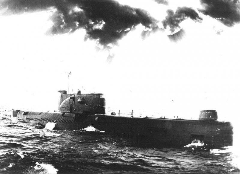
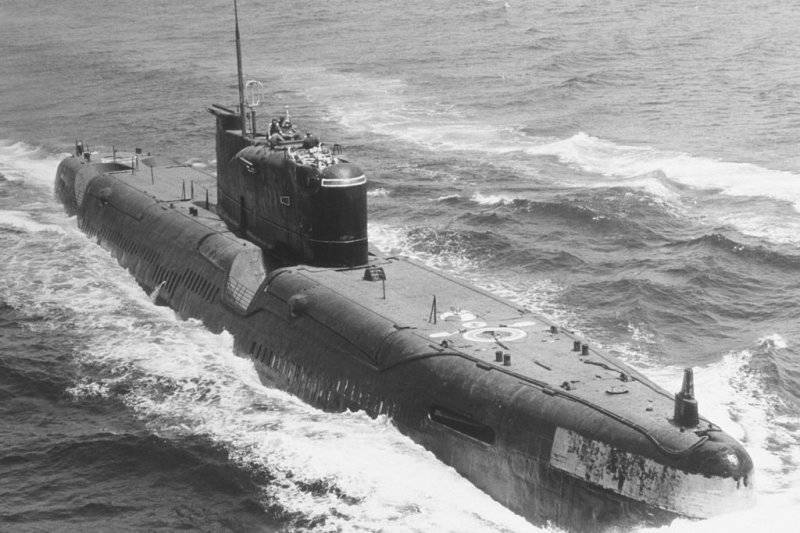
DPLRK Ave. 651 in the campaign on the Baltic
The project was developed in the Central Design Bureau of Rubin marine equipment under the direction of A.S. Kassatsiera, chief designer and his deputies S.E. Lipelisa, F.A. Sharov, K.Z. Saravaisky. The main observer of the navy was appointed IA. Kotsyubin, captain of the second rank. Development of working drawings and those. Documentation started in the first quarter of 1959 and completed in the first quarter of 1960. Verification of placement on the submarine of personnel and equipment was carried out by prototyping. At plant No. 196, the compartments from 1 to 3 were made up; at the plant number 194 - 4 and 5 bays; at the Baltic Shipyard - compartments from 6 to 8. In the future, all the technical documentation of the 651 project, as directed by the SME managers, was transferred to the CDB-112 SMEs.
The submarine of the 651 project, like all the Soviet-made submarines of that time, was built with a double-hull structure with a superstructure and a well-developed durable logging fence. The robust case was formed from a cylinder with a diameter of 6,9 m and truncated cones in two extremities. The robust housing was divided into 8 compartments by means of transverse flat waterproof bulkheads. All bulkheads are calculated on the pressure 10 kgf / sq. See the ribs have been installed inside and outside the sturdy casing. For loading / unloading of the main mechanisms, it was possible to cut a set of durable hull and cladding sheets, followed by butt-welding. Robust felling was oval in shape, and the felling roof had the shape of a circular cylinder. The main ballast was in 14 tanks. Tanks №№ 4 and 11, were emergency ballast. They served to restore the buoyancy of the vessel in case of loss of tightness of one of the two rocket containers. Tanks Nos. 2, 3, 5, 7, 12 and 13 were fuel-ballast. These tanks had Kingston and were strong. The rest of the main ballast tanks, with the exception of No. 1, which had Kingston and was located in the bow of the boat, were filled through the scuppers. All double-breasted tanks had separate ventilation. The control valves for ventilation and kingston were hydraulic remote.
The mass of rocket fired is replaced by the reception of strong water tanks. The tanks were located in the 2 compartment and in the vicinity of the feed containers in the double-breasted space. The normal fuel supply was located inside the robust hull in 5-and fuel tanks and in 6-and outboard tanks, two of them in the extremities, and the rest in the double-breasted space. The design of the outer and durable shells was calculated taking into account the requirements of anti-nuclear protection.
Great difficulties were caused by the development of the feed complex, whose main task was to ensure high speeds while reducing the noise level of the submarine. These difficulties were aggravated by the fact that the submarine had high-power propeller motors (6 ths. Hp), requiring the installation of propellers of a size in which the screws were not installed in the adopted main dimensions of the submarine, and an increase in the latter caused the loss of speed. In addition, the rowing motors hardly fit into the size of the robust hull, limiting the collapse angle of the shaft line. After some constructive studies, we chose the variant in which guide nozzles were used for the propellers, and the stern tip was given an architectural form that allows reducing the length of the submarine. Propellers designed as low noise. The selected propulsion complex allowed the diameter of the propeller to be reduced to an acceptable value and, at the same time, to increase the critical travel speeds (that is, speeds at which the noise of the ship increases significantly).
All hull structures that provide immersion to the maximum depth, as well as transverse flat bulkheads of the robust hull were made of AK-25 steel, the yield strength of which was 60 kgf / sq. Mm. For the manufacture of individual structures used steel grade AK-27 (yield strength 52 kgf / sqmm). The durable outer tanks, the outer hull, the durable logging fence and the stabilizers of the first five submarines were made of low-magnetic steel 45Г17УЗ, (yield strength 40 kgf / sqmm). On the remaining submarines, these constructions were made of SHL steel.
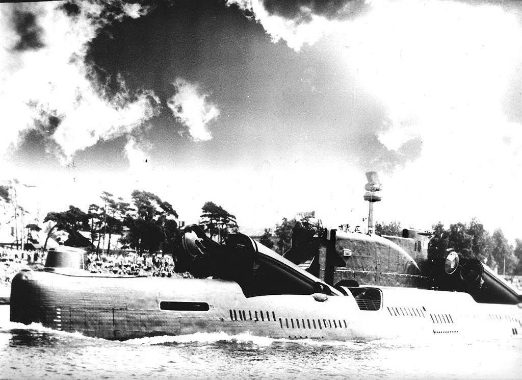
DPLRK Ave. 651 at the parade in honor of the Navy Day in Liepaja. Rocket containers are raised and their covers are open.
Shipyards during the development of low-magnetic steel 45Г17УЗ met with technological difficulties associated with the editing and cutting of steel. This is due to the increased distortion of low-magnetic steel, due to the physical properties of steel - low thermal conductivity and increased linear expansion coefficient. In addition, 45-X17ÜZH is difficult to fur. processing. All this has led to an increase in the volume of work on the editing and fitting of structures, and, consequently, has led to a significant increase in residual stresses in structures.
The outer hull of the serial submarines of the 651 project was covered with an anti-hydrolocation nonresonant coating with horn channels NPRK-4 DZ. However, on the first six vessels such coverage was absent, because by the time the submarines were ready, the technology had not yet been mastered. The surface displacement of submarines when installing the coating increased to 3300 cubic meters.
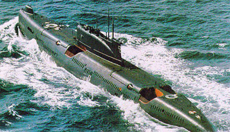
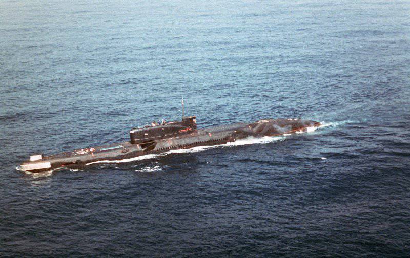
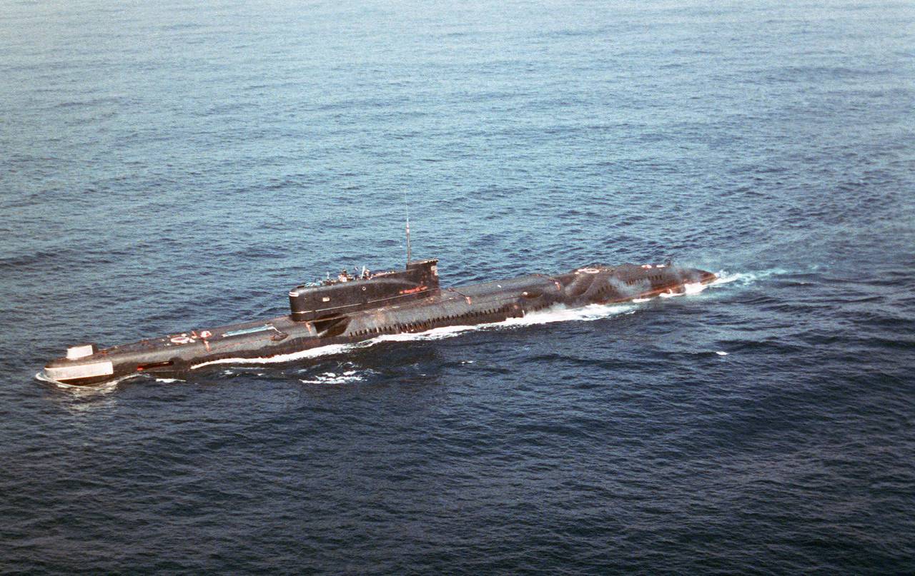
DPLRK Ave. 651 in the sea
The power unit of the submarines of the project 651 included:
- two main diesel engines 1ДХNUMX (Kolomna Plant), twelve-cylinder, four-stroke, non-reversible, with gas turbine supercharging, with a built-in gearbox, power each at 43 revolutions per minute 440 thousand hp and diesel engine 4ДЛ1 (Kolomna Plant), six-cylinder, four-cycle with gas turbine supercharging, power at 42 rpm 700 hp, paired with generator PG-1720. Submarines installed a remote automated control system designed to control diesel engines, tire-pneumatic couplings, gas exhaust flaps and air supply to the engines, including signaling about their operating parameters and the position of tire-pneumatic couplings. Also, the remote automated control system served to control the RDP clamps, as well as to ensure the blocking of diesel engines and main rowing motors during their operation in the RDP mode and to protect diesel engines by certain limiting parameters. In addition to the remote control station, local control stations located at the front ends of diesel engines could be used to control diesel engines. The remote automated control system significantly simplified maintenance during operation and allowed one person outside the diesel compartment to control the diesel engines. The special features of a diesel plant include the fact that their gas outlets are made of titanium alloy;
- a pair of main rowing electric motors PG-141 (power of each at 500 revolutions per minute 6 thousand hp) and a pair of electric motors of economic progress PG-140 (power of each at 155 revolutions per minute 200 hp);
–A rechargeable silver-zinc battery type 30 / 3, which consisted of four groups, each on the 152 element. The maximum power of the discharge current - 14 thousand amperes for 90 min. The maximum capacity of the discharge mode is 30 thousand ampere-hours at a current of 250 amperes. Battery life from 35 to 40 conditional cycles or from 12 to 18 months in time. In order to ensure maximum battery discharge conditions, a closed-loop cooling system with distilled water was provided. In addition to a much larger capacity compared to the lead battery, silver-zinc allowed a break in the charges, if necessary, incomplete carrying them out, and also did not require refilling during the warranty period of operation. The battery was equipped with a remote control system for work, which facilitated its maintenance. Due to the lack of sufficient silver in the country in 1961, it was decided to limit the use of rechargeable silver-zinc batteries to about half of the 651 series of submarines, and subsequently the number of ships with this battery was reduced to three. On the remaining submarines, 60CM-P lead batteries (ed. 422) were installed in the number of 448 e-batteries. (in each group 112 e.) The maximum discharge current of this battery is 9 thousand. And within an hour, the maximum capacity of the continuous discharge mode 15 thousand A • h at discharge current 250 A.
To control the rowing motors, we used shields that had a water cooling system and provided for starting, reversing, as well as other envisaged generator and motor modes. To maintain the purity of distilled cooling water, on which the insulation resistance of the rowing motor control panels and the battery directly depends, ion-exchange filters were installed in the water-cooling system. Rechargeable silver-zinc batteries, as well as water cooling of the rowing motor control panels on domestic submarines were used for the first time.
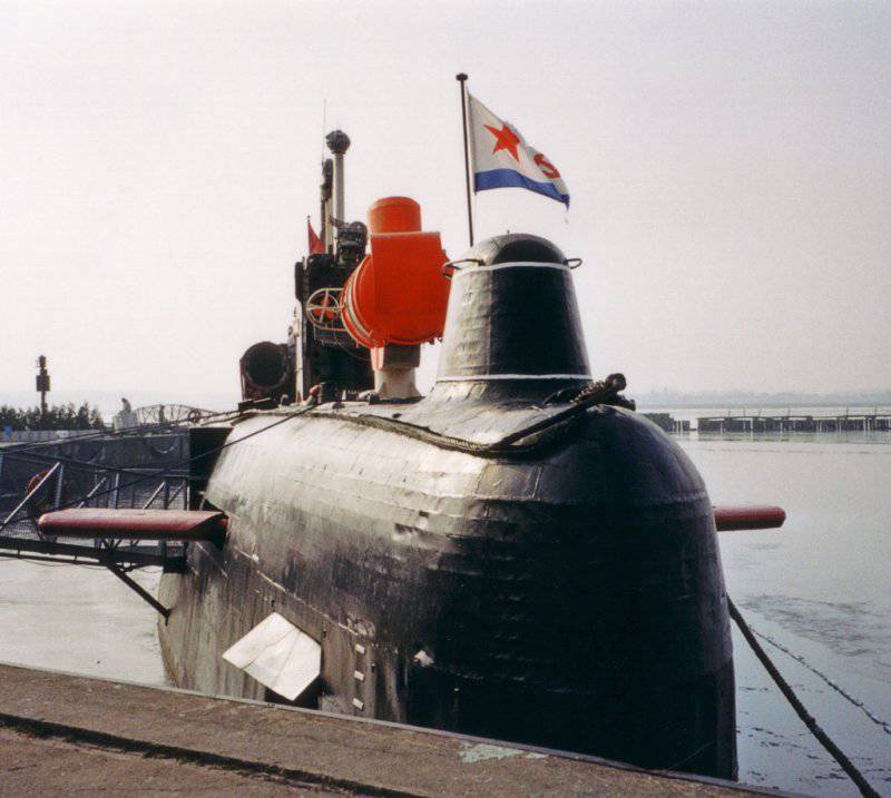
DPLRK Ave. 651, the “Argument” missile guidance station is in a combat position
The main armament of the submarine project 651 - missiles P-5 and P-6. Containers designed for storing and launching missiles are interlocked in pairs and installed — one in the bow and the other in the stern from the cabin fencing.
The submarine’s missile armament based on a constructive and circuit design provided for the possibility of single launches of the P-5 or P-6 cruise missiles from any container, as well as a four-rocket salvo with a launch sequence 4-1, 3-2. In this case, the possibility of firing different types of missiles during a single ascent of the submarine was excluded.
Containers for launching rockets were raised at an angle of 15 degrees. Lifting and further locking of containers, closing, opening, locking of covers was made by hydraulic drives. The hydraulic cylinders, which are located outside the robust hull, were connected to an autonomous hydraulic system. The hydraulic cylinders, which are located inside the robust hull, were connected to the general ship hydraulic system. This was done to prevent the outboard water from entering the general hydraulic system of the ship, as well as to protect the executive bodies from corrosion. The launch of cruise missiles was carried out only under the condition that all the pre-launch preparation operations were carried out in the adopted sequence, including the operations of lifting and locking containers and lids. In this regard, in the control panels, a lock is provided, which does not allow the launch of missiles in case of non-fulfillment of at least one of the operations. The start scheme provides emergency dumping of faulty CS with the help of starting engines. The submarine had the opportunity to load the missiles at any stage of the pre-launch preparation after closing the lids of the containers or with the lids open of one of the containers.
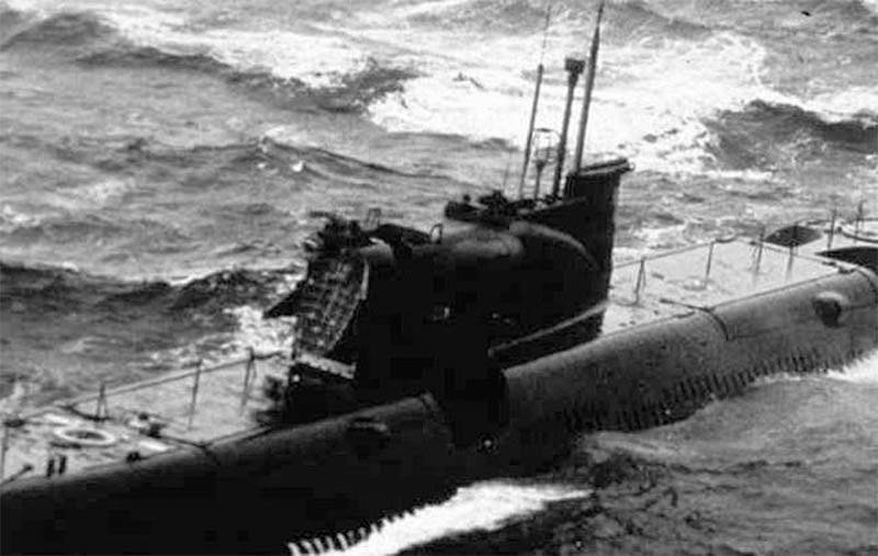
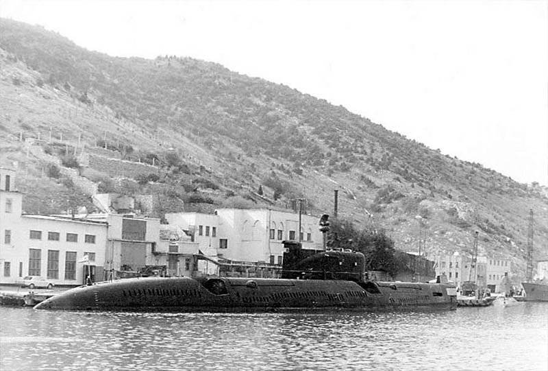
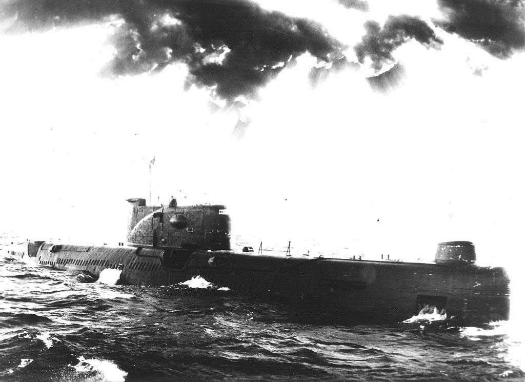
DPLRK Ave. 651 in the database
The composition of each container included:
- fire extinguishing system;
- air gas analysis system;
- internal irrigation system;
- air gas analysis system;
- ventilation system, gas cleaning, dehumidification, maintenance of air pressure;
- external irrigation system;
- heating system;
- devices for measuring pressure and temperature;
- devices of water availability and determination of its level.
Missiles were fired only from a surface position, with raised, locked containers and open covers. The speed of the submarine at the same time should not exceed 8 nodes, and the sea state is not more than four points. The emergency rocket could be reset under the same conditions.
The control system of the P-6 missile system made it possible to accomplish the tasks of controlling the flight of the missile and pointing with a radar reamer at a target that is within or beyond the geometric visibility of the carrier. When several targets were detected, there was the possibility of selective destruction by transferring a radar image of targets from a cruise missile to a submarine and sending back a command to select a target.
Determination of the bearing and range for the P-6 missiles were made by the ship equipment “Argument” according to data received from the reconnaissance means, as well as from the navigational aids of the submarine. The antenna system “Argument” is an almost flat design, with an area of about 10 square meters, with a sphere protruding on the 1,5-2 meter, which carries emitters. This antenna was mounted on a swiveling mast in the bow part of the wheelhouse fencing. In the off position, the antenna automatically got into the cabin fence with several successive operations, and the fairing installed on the back side of the antenna on the same mast, in this case, was the front part of the fence. The design of the antenna rotator was reliable and was later adopted for subsequent submarine projects.
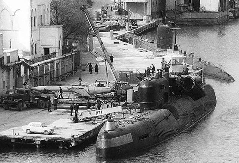
Loading of missile ammunition at DPLRK B-67 Ave. 651 in Balaclava, April 1994
To receive external target designations for the missile system from helicopters and airplanes, the submarine was equipped with “Success-U” equipment.
"Sever-A651U" - the control system of the P-5 - was intended to control missiles in the event of strikes against an area target. To do this, it was introduced distance to the target, as well as other basic parameters. In flight, the rocket was controlled by an autopilot. The height flew - about 400 meters, while its trajectory within the radio horizon was corrected from the board of the submarine. After overcoming a certain distance by a rocket, which was determined by the time counter and the inertial system, it swooped down on the target. Estimated QUO when shooting at full range (about 500 thousand. M) was 3 thousand meters.
The X-NUMX P-5 missiles were decommissioned by the 1966 submarines and only the P-651 missiles were left. Therefore, the equipment that belonged to the П-6 missiles was removed from the boats.
The 651 submarine torpedo armament consisted of 6- and 533-mm torpedo tubes in the bow (without spare torpedoes) and 4-400-millimeter-sized torpedo tubes in the stern (eight spare torpedoes). The bow torpedo tubes of caliber 533 mm are parallel to the center plane, and the stern are angled 3 degrees to the center plane of the submarine. Torpedo tubes of caliber 533 mm provided for firing electric and steam-gas torpedoes, including 53-56, 53-57, 53-58 and СЭТ-53, 2200 kg mass at depths less than 100 meters. Torpedo tubes of caliber 400 mm ensured firing with electric torpedoes MGT-1 and MGT-2 at a depth of less than 150 meters and Anabar devices (jamming devices) at depths less than 250 meters. On submarines, starting with K-156, a recharge device for 400-millimeter feed torpedo tubes was installed. Recharging was performed using an electric drive having an automatic separation of carriages after landing torpedoes on the stoppers. The reload time of four torpedo tubes is about 30 min.
During the construction of the submarines of the 651 project, there were racks in the second compartment for storing torpedoes of caliber 533 mm. The main purpose of the installation of racks was that in wartime, due to deteriorating living conditions of the personnel, it was possible to accept twelve spare 533-millimeter torpedoes for nasal TA instead of the standard eight spare 400-millimeter torpedoes for fodder torpedo tubes. In this case, the number of torpedoes on the submarine increased to 22 units. Loading 533-millimeter spare torpedoes carried out through torpedo tubes and specials. hatches in the bulkhead between the first and second compartments. These torpedoes were intended solely for reloading four torpedo tubes.
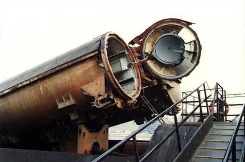
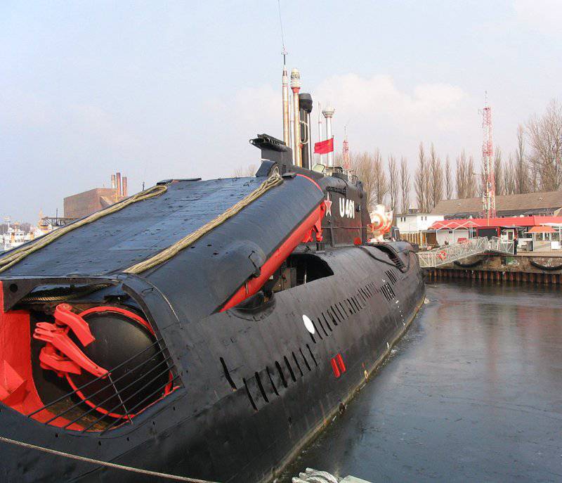
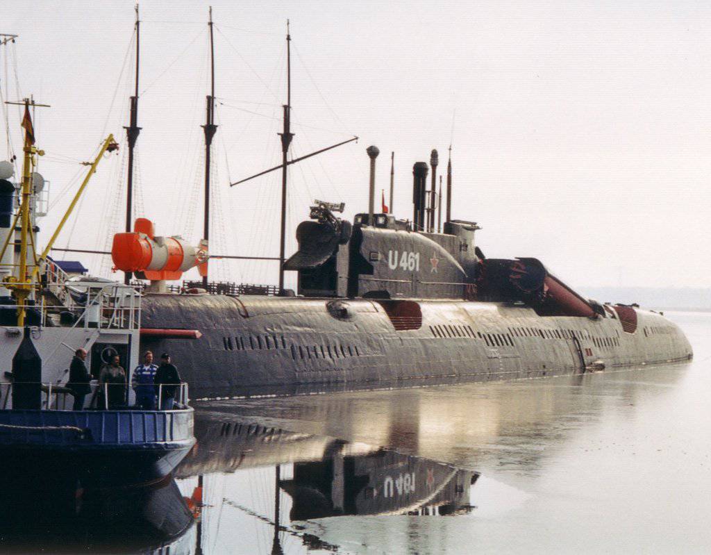
U-461, rocket container
651’s project-wide shipboard devices and submarine systems basically corresponded to the 641 project’s submarine torpedo submarines, except for the following:
- due to the large size of the buoyancy margin, the bore diameter of the main ballast emergency blowing column was increased to 60 millimeters (on vessels of the 641 project it was equal to 32 millimeter), this caused the manual control of the emergency blowing valve to become difficult and it was replaced by pneumatic.
Later it became clear that the pneumatic control accelerates the opening of the column shut-off valve, that when air is bypassed, it instantly heats up in the unfilled pipeline and in the presence of oil deposits on the inner walls of the pipes, an explosion of oil vapors may occur ("diesel effect"). Similar incidents occurred on atomic submarines of the first generation (659 and 675 projects). Therefore, high-speed shut-off valves installed on the columns of emergency blowing were replaced by pneumatic valves having a by-pass device regulating the pressure build-up rate in the emergency blowing pipeline;
- manipulators of hydraulic control of executive bodies in the hydraulic system were replaced with electromagnetic spools, which were located near the executive bodies and were remotely controlled from the control panels;
- The stabilizer "Marble-2" was installed as well as the gyro-stabilizer stabilizer of the course "Granit-2".
The habitability conditions on the submarine of the 651 project were significantly improved compared to the submarines of the project 641. All personnel were provided with berths, located in the bow of the boat, mainly in the first and second compartments. The officers of the submarine was located in cabins. The conditions of the microclimate and the gas composition of the air at the combat posts and in the premises were provided by the centralized ship's air conditioning and ventilation system, the physiological air conditioning system in the crew rest areas and at the combat posts, the heating system, and the like. The overall centralized ventilation system of the air was serviced by one exhaust and one blower fan (each 9,5 thousand cubic meters per hour), and had an air cooler and an electric heater for cooling or heating the outside air supplied to the interior.
In addition, autonomous air coolers were installed at combat posts and in living quarters, which worked on outboard water or on so-called. working cold water, which is cooled by two freon refrigerators SPHM-FU-90 (productivity of each 85 thousand kcal / hour).
Gas purification filters were installed in various places of the submarine to clean the air from various harmful gaseous impurities. Air regeneration was carried out with RDU installations. They used hopkalitovs attachments-consoles. DUK device was provided to remove debris to the depth of immersion in 200 m.
On submarines of the 651 project, a propulsion system was used, consisting of a guide nozzle and a low-noise propeller. Full-scale acoustic and sea trials of the 651 submarines showed that the use of guide nozzles increased critical travel speeds by approximately 30%, and the propulsive coefficient by approximately 20%. An analysis of the results made it possible to conclude that the use of this propulsion complex increased the critical travel speeds by a factor of two compared with submarines without this complex. Thanks to the use of noise-damping and anti-hydrolocation coatings, soundproofing mechanisms from the hull, the new propulsion complex, as well as other activities, the noise level of the submarines was lower than on other Soviet diesel submarines, although it did not fully meet all the requirements of the navy.
The construction and testing of submarines of the 651 project was accompanied by considerable difficulties. The main ones were:
1. Testing diesel engines 1Д43. Diesels were delivered to the head submarine, which were not accepted by the interdepartmental commission. Later, directly on the submarine, work was repeatedly carried out aimed at upgrading individual units of diesel engines and eliminating deficiencies.
2. Mastering a silver-zinc battery, first used on a Soviet submarine. With the start of testing due to internal short circuits, individual batteries began to fail. The number of batteries disconnected from the battery on the head submarine was 61 of 608 units, which was approximately 10 percent.
3. There is no possibility to conduct all tests on the Baltic Sea, since there were no necessary depths for conducting deep-sea diving and testing sites for missiles. This required the redeployment of submarines to the Northern Fleet from the Baltic Sea with a transition near the Scandinavian Peninsula.
4. The duration of the test complex P-6. During the state. tests of the boat on the Barents Sea were conducted rocket tests weapons, except for the hot race of the main engine with the current P-5 mockup, which was performed in Baltiysk from February to March 1963 during the factory tests. After the marching engines of each individual rocket were held, and the joint marching of the engines of the first and fourth container missiles, two launchings of the P-6 rockets were conducted - a single launch and the launch of two missiles. In addition, a single launch of the P-5 rocket was carried out. The P-6 missiles were fired at the target ship of the 1784 project from the 1 and 4 containers in the sequence 1-4. The firing of the P-6 missiles showed good results - all three missiles launched hit the target. A single launch of the P-5 was conducted from the 2 container over the battlefield of the sea range, while it was not possible to establish the coordinates of the point of impact.
As a result of tests of the P-6 complex, it was established that single P-6 missiles can be fired from any container of the submarine, and firing of two P-6 missiles is possible from No. 1 and No. 4 containers in the 1-4 sequence and from No. 2 and No. 3 containers in the sequence 2-3. This launch sequence during volley fire was caused by the need to minimize the effect of missile propulsion systems of missiles operating in prelaunch mode for the operation of rocket engines that start from adjacent containers, and the effects of exhaust gases of propulsion and launch engines of launching rockets on the operation of engines of rockets located in adjacent containers.
These phenomena were noticed even during the first missile launches of the P-5 complex and, in particular, during the missile firing of the submarine of the 659 project. At first, it was believed that the unstable operation of the main engines during salvo firing was caused by the increased resistance of the gas fences, due to their unsuccessful form. But the tests that were conducted on a two-container spec. in July-August, 1960 showed that the chosen design and form of the gas fences does not have a decisive influence on the operation of the main engines. During the same tests, it was revealed that a working main engine of a rocket preparing for launch, sucks in part of the rocket starter and main engine gases starting from a nearby container through the air intake, therefore the stability of the engine of the rocket is needed, which is being prepared for launch. The engine speed is reduced by approximately 10-15 percent. To determine the activities that are necessary to ensure salvo fire from two or more volleys, the two-container stand was converted into a four-container universal stand, which allows you to change the relative position of the two adjacent blocks with their gas outlets, which are allowed by the submarines of the K -5 and P-6.
The firing of the P-5, P-5D, P-6 and P-7 missiles, which were conducted at the universal stand in 1963 – 1964 godo, showed the following:
- the form of gas outlets has no significant effect on the work of the missile propulsion engines;
- Outgoing gas jets of the launching unit and the main engine of the starting rocket significantly affect the operation of the rocket preparing for launch, mainly due to the high temperature. Gas streams, getting into the air intake of the main engines, cause a breakdown of the air flow and an increase in the temperature behind the compressor. This leads to a decrease in speed and in some cases, the stop of the main engine, which operates in the "full throttle";
- also the exhaust gas jets of the rocket affect the nose of the rocket, which is located in the nearest container, behind the container with the launching rocket and can damage it.
According to the results of tests that were conducted by the interdepartmental commission of the Navy and GCS VSNH, chaired by Pustyntsev, recommendations were given on the sequence of launches of cruise missiles from a submarine at volley fire, as well as on the operating modes of the missile propulsion engine, which is being prepared for launch. For submarines 651-th project with a four-rocket salvo missiles P-6 recommended launching missiles in the sequence 1-4-2-3. At the same time, the interval between the 4 and 2 rockets was significantly increased compared with the interval between the 1 and 4 rockets, as well as the 2 and 3 rockets. Delays were 6-26-6 seconds.
During the factory and state. The test submarine passed over 10 thousand miles in surface position and about 1 thousand miles under water. The Commission of the State Registration Committee for the head submarine of the 651 project noted that “the main positive qualities of the submarine of this project are:
1. universality of weapons, giving the opportunity to solve different problems;
2. excellent handling in surface and submerged positions;
3. low fillability of the superstructure when the sea is up to 9 points;
4. conditions of habitability for personnel have significantly improved in comparison with other diesel-electric submarines ”.
In addition, the commission noted a number of shortcomings of the submarine, the main ones of which were:
1. the lack of reliability of the silver-zinc 30 / 3 rechargeable batteries installed on the head submarine, and the impossibility of discharging the batteries with low currents, which greatly complicated the control of the rowing unit, which made it difficult to manufacture maneuvers;
2. lack of unified side connectors for П-6 and П-5 missiles. With the existing design of the board connectors, their change during the transition from the P-5 complex to the P-6 complex (and vice versa) requires from 2 to 3 a day (it should be noted that after removing the P-5 missiles from service, this question has disappeared).
In its conclusion, the Commission for State Acceptance noted: “In general, the submarine of the 651 project in terms of its weapons, ship systems, power plant and electronic weapons, devices and mechanisms is a modern ship, which in its tactical and technical characteristics exceeds all existing diesel-electric submarines, and is capable of performing a wider range of tasks. ”


The first five submarines with outer hulls, in the construction of which low-magnetic steel was used, began to be operated in the 1962 year. However, already in September 1966 of the year on one of the vessels found a lot of significant damage in the lining of the outer hull in the form of nonstandard and through cracks of various lengths near the tanks of the main ballast. The conducted surveys established that all light hull structures made of low-magnetic 45-17-UZE steel and in contact with water, through 5 years of operation, are subject to nesting and through cracks.
Due to the prevailing circumstances, the Navy and the SMEs made a number of joint decisions. For each submarine project, in accordance with these decisions, design, technological, and protective measures were developed to increase the corrosion-mechanical strength of the light hull, and later durable outdoor tanks, which were made using 45Х17УЗ steel. They also developed a number of instructions and guidance documents on the correction of defects (after the elimination of defects, the magnitude of the magnetic field strength of the submarine, due to the specification for the construction of the submarine, was not guaranteed). Usually these works were combined with the regular modernization or repair of submarines.
Modifications of the submarines of the project 651 / 651-K Juliett class.
The submarine K-81, which was commissioned in 1965, was completed according to the 651-K project. The vessel was equipped with a receiving antenna, as well as with the equipment of the Kasatka-B satellite target designation system. Such a system had previously been tested on a submarine K-68 of the same series.
On the K-68 retrofit submarine in June 1969, special prototype containers of future rescue pop-up cameras for submarines were tested in the Barents Sea. The study of the possibilities, as well as ways to create rescue chambers, began the Malachit joint venture with the Navy ASS in the 1964, when the question arose of rescue support during deep-sea diving of head submarines, the depth of which leaves more than 400 meters. Those. the design and detailed design was carried out in the 1967 year by the Malakhit SPMBM, and the construction of a pair of containers was carried out in 1968 at the Krasnoye Sormovo plant.
At the Red Sormovo plant in 1985, the K-651 submarine was re-equipped according to the 68-E project. It was experimentally equipped with an auxiliary small-sized atomic power plant WOW-6.
Some submarines of the 651 project at the end of the 1970s. (Simultaneously with the SSGN of the 675 project) were re-equipped with the Basalt anti-ship P-500, although by this time their real combat stability was already highly questionable.
Submarine construction program.
In total, it was planned to build 72 submarines of the 651 project, however, ultimately, the program was significantly reduced. The head submarine (K-156, serial number 552) was laid at the S. Ordzhonikidze Baltic Shipyard (No. 189) 16.11.1960 and launched the 31.07.1962. Mooring trials were initiated by 27.08.1962, and factory trials that were conducted in Baltiysk and Tallinn - 22 December 1962. The submarine 21 May 1963, was presented to the state. the tests that completed 10 on December 1963, after which they signed the acceptance certificate. At the same plant in 1964, the second boat of the 651 project was built, and the remaining 14 ships built between 1965 and 1968 the year at the Red Sormovo plant (No. 112) in Gorky.
The boats of the 651 project were mainly part of the Northern Fleet. The main place of their use was the Mediterranean Sea. Later they were transferred to the Baltic and Black Sea fleets, since the actions of these diesel-electric submarines with cruise missiles in these theaters were much more responsive to the combat capabilities of the ships — only in closed seas and in the near zone could they be reliably protected from anti-submarine forces. Initially, all submarines of the 651 project were classified as cruising, but since July 1977, they have been reclassified into BPL. These submarines in the west received the designation Juliette class.

In general, the submarines of the 651 project (as well as the 675 project) completed the evolution of the development of submarines of the armed forces of the Kyrgyz Republic with a surface launch in the navy of the Soviet Union. These ships from the 1980-ies, they began to be removed from the fleet and by the beginning of the 1990-x they passed for scrapping. At the same time the boats - B-24 and B-77 - were sold to the west and there they were turned into museum exhibits.
The main tactical and technical characteristics of diesel-electric submarines with cruise missiles of the project 651 / 651-K:
Surface displacement - 3174 tons;
Underwater displacement - 3750 tons;
Basic dimensions:
the longest length (KVL) - 85,9 (n / d) m;
maximum width - 9,7 m;
the largest draft of KVL is 6,9 m;
The main power plant - diesel-electric;
- 2 diesel 1Д43, total power 8000, hp (5880 kW);
- 2 GED PG-141, total power 12000 hp (8820 kW);
- 2 HED economic progress PG-140 total power 400 hp (294 kW);
- 1 diesel 1ДЛ42 equipped with PG-142 generator with power 1720 hp (1264 kW);
- battery 60CM-P (4 groups, 112 elements) or 30 / 3 (4 groups, 152 elements);
2 propeller;
2 shaft;
Full surface speed - 16 nodes;
Economic surface speed - 8 nodes;
Full submerged speed (SCS / SCAB) - 18,1 / 14,5 nodes;
Economic underwater travel speed - 2,8 nodes;
Navigation range:
- in the surface position - 30000 miles at a speed of 8 nodes;
- under RDP - 18000 miles at a speed of 7 nodes;
- submerged (SSB) - 810 miles at speed 2,8 knots / 27,8 miles at speed 18,1 knots;
- submerged (SCAB) - 350 miles at speed 2,8 knots / 14,5 miles at speed 14,5 knots;
Immersion depth - 240 m;
Extreme depth of immersion - 300 m;
Autonomy - 90 days;
Crew - 78 people, including 10 officers;
Impact rocket armament:
- PU SCRK P-5D or P-500 or P-6 - 4 X 1;
- PKR 4K88 (SS-N-3B "Sepal") or KP P-5D (SS-N-3C "Shaddock") (subsequently removed) or PCR P-500 "Basalt" (SS-N-12 "Sandbox ") (Installed during the modernization of the submarine) - 4;
Torpedo armament:
- 533-mm torpedo tubes - 6 (bow);
533 mm torpedoes SET-53, 53-56, 53-57, 53-58 - 6 or 18
- 400-millimeter torpedo tubes - 4 (fodder);
400-mm torpedoes MGT-1, MGT-2 - 12 or 4;
Mine armament:
- can carry mines instead of a part of torpedoes - n / a;
RADIO ELECTRONIC ARMS:
BIUS - no data;
Radar system of general detection - RLK-101 (Snoop Slab);
Hydroacoustic system:
- Arktika-M (Pike Jaw);
- MG-10 noise-finding device;
- station ZPS MG-15;
- sonar MG-13;
- NEL-6 echo sounder;
- echoledomer EL-1;
Radar fire control system:
- “Argument” (Front Door) for the SCRC;
- “Success-U” for targeting the SCRC;
- Kasatka-B (Punch Bowl) space targeting for the SCRC, (only on boats of the 651-K project);
EW facilities:
- Nakat-M (Quad Loop D / F) RTR;
- “Van” (Stop Light) EW;
- ARP-53 with the prefix KI-55 radio direction finder;
- P-670, “Wave-K”, P-309 radio intelligence;
Navigation complex:
- “Force H-651”;
- "Lyra-P" astronavigation;
Radio communication complex: 2 p / p "Onyx-P", p / p P-609M (VHF), p / p P-651, P-657 (KV), p / p P-676;
State recognition radar: "Nichrom-M".
По материалам сайта http://www.atrinaflot.narod.ru
Information