Experimental aircraft Martin Marietta X-24A (USA)
From the beginning of the sixties, NASA specialists studied the concept of the Lifting body, which offered an original design of an aircraft with a carrying fuselage, replacing a full-fledged wing. The first projects in this area were implemented by the aerospace agency independently or in cooperation with aircraft manufacturers. Later, after getting real results, the US Air Force became interested in unusual ideas. With their help and to solve military problems, an experimental aircraft Martin Marietta X-24A was developed.
At that time, the Air Force Command showed an increased interest in promising aerospace complexes for various purposes. In particular, the possibility of creating reusable spacecraft capable of carrying one or another payload was studied. To simplify the operation, such “space bombers” or other equipment had to be returned to Earth using horizontally flight. The solution of such problems was associated with the need to conduct various studies, both in wind tunnels, and with the use of full-size experimental machines. Looking ahead, it should be noted that work in this direction in the future led to the emergence of the Space Shuttle project, which has come to active operation in the interests of various customers.
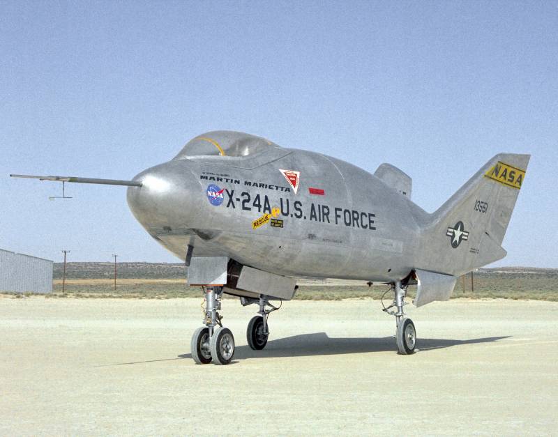
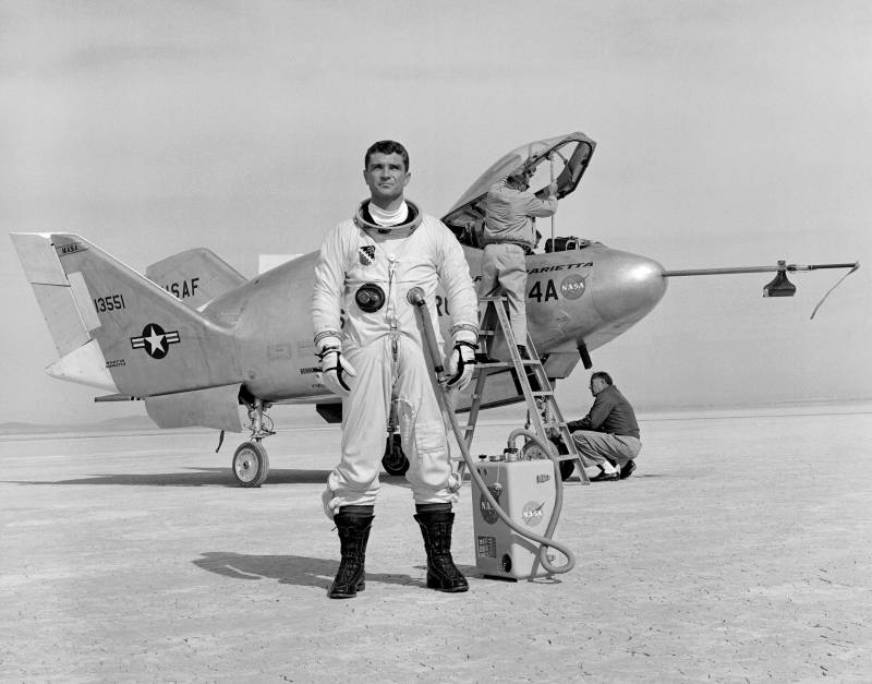
Experienced Martin Marietta X-24A at Edwards Air Base
In 1966, NASA, the Air Force, and Martin Marietta jointly implemented the X-23 PRIME research project. His goal was to create a model of the aircraft, built on the scheme of the Lifting body and capable of making a planning flight in the upper atmosphere. Tests of three models of this type showed that it is possible in principle to solve the problems posed, but for this to happen, the existing project needed to be refined in a certain way.
After the tests of the experienced X-23 were completed, the aerospace control, air force and Martin-Marietta signed a new agreement to create an experimental aircraft. The next project received the official "military" designation X-24A. The development company used the working title SV-5J. There were no additional project names or nicknames.
In the framework of the previous project X-23 used so-called. carrying the fuselage, in its form similar to the flying scheme of the aircraft "flying wing". For several reasons, the new project decided to use a different form of the main units and bearing planes. The prospective X-24A prototype should have a drop-like shape without bearing planes made in the form of a traditional wing. At the same time, the use of a stabilizing tail unit was mandatory.
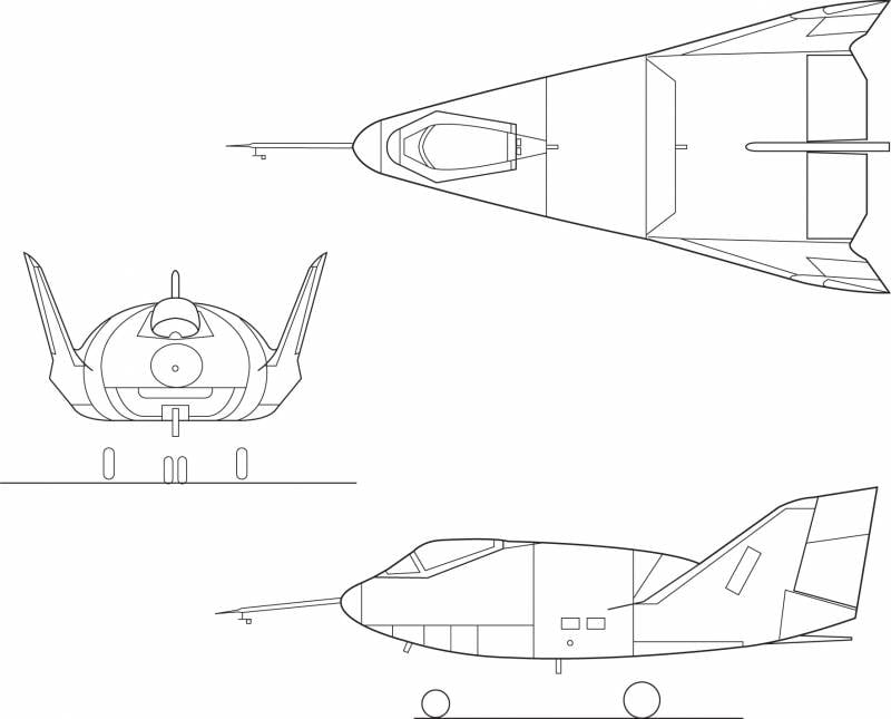
Projection of the aircraft
The X-24A project proposed the construction of an all-metal aircraft adapted to high mechanical, aerodynamic and temperature loads. To obtain high flight characteristics should use a special form of the fuselage and planes. In addition, it was proposed to equip the car with a liquid-propellant rocket engine with sufficient traction characteristics. This technical look has already been used in previous research projects and, in general, has made a good showing.
In accordance with the new objectives of the project and the specifics of the future operation, the new aircraft received the fuselage of the original design, which was noticeably different from the previous "supporting bodies". The proposed all-metal fuselage had a smaller width of the nose and center with a greater height. In the side view, the car looked like a standard wing profile, complemented by a vertical tail.
The nose of the X-24A fuselage had a shape close to a spindle. Immediately behind the rounded side fairing, the upper surface and the bottom of the fuselage diverged, forming a structure with a gradually increasing elliptical section. Then the sides were diluted to form a triangular structure in the plan. The upper part of the fuselage, in turn, noticeably rose upwards. Right behind the nose cone, a straightened bottom began, smoothly connecting to the sides with the help of curved sections of the skin. The width of the flat part of the bottom increased towards the tail. The fuselage tail section had a rectangular shape with a narrowing triangular profile. The tail end of the fuselage was formed by a polygonal opening, enclosed by control planes.
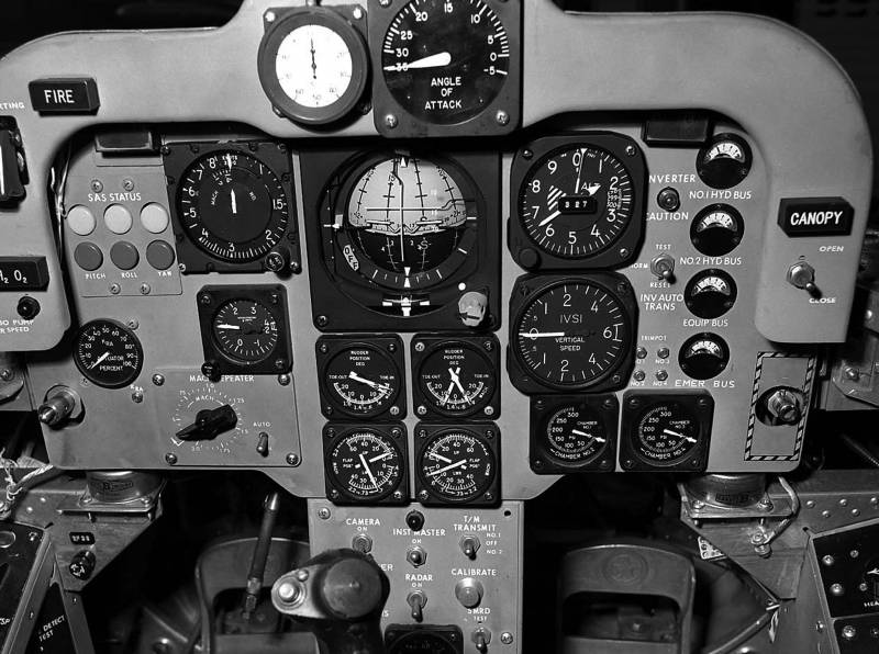
Dashboard
According to its layout, the fuselage of the new flight prototype corresponded to the previous developments of the Lifting body program. The nose part was given under the cockpit, for which there was the instrument compartment. In the tail were placed the engine and fuel tanks. Part of the other volumes in the nose and tail was given under the niche for cleaning the chassis.
In the rear fuselage, on its sides, with a collapse outward, a pair of keels of a large sweep was installed. Behind them were mounted relatively large two-section rudders. In the center of the fuselage, between the main keels, there was another vertical plane. Unlike the other two, it was not completed with a wheel of height. At the same time it had a nozzle of one of the gas rudders. Below the central keel, between two pairs of elevons, were the nozzles of the main engine.
All mechanization and all the steering wheels were located only in the tail of the machine. The pitch and roll control was proposed to be carried out using two pairs of elevons attached between the keels. The first was on the upper surface of the wing and in a neutral position was its continuation. The second one continued to bottom. Aerodynamic rudders were complemented by a pair of nozzles of gas systems of similar purpose.

View of the left side of the cabin
The pilot had to work in the nasal single sealed heated cabin. Unlike some previous samples, the cabin was closed by a single large lantern, not divided into several parts. For access to the cockpit, the lantern went up and back with a fairly large section of plating. The large lantern provided a good overview, which made it possible to do without additional glazing in front of the cabin.
The pilot was placed in the ejection seat of the production model. At his workplace there was a dashboard with all the control and navigation devices, as well as a pair of onboard panels. Flight control was carried out using the central knob, engine control knob and a pair of pedals. Also on the dashboard and side panels there were many controls for all onboard systems.
Again, it was proposed to equip the experimental machine with its own power plant. In the rear fuselage placed liquid reaction rocket engine Reaction Motors XLR-11 3600 kgf. The four-chamber engine could be started at the command of the pilot and change the thrust in accordance with the position of the control knob. Also, the engine was associated with gas rudders.
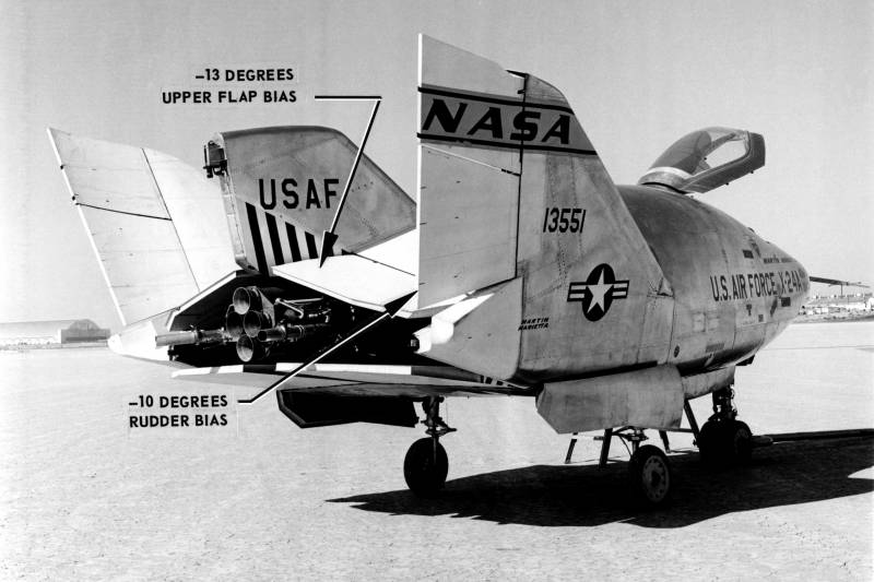
The tail of the X-24A
X-24A received a three-point chassis based on serial components aviation technicians. Under the cockpit was a bow rack with two small-diameter wheels. Under the root of the keels placed a pair of main racks with larger wheels. Using automated drives, all racks retracted into the fuselage by turning back. Niches were covered with rectangular covers of longitudinal arrangement.
From the previous models built as part of the research program, the new aircraft differed not only in shape but also in size. The length of the car was 7,47 m, the maximum width - 3,51 m. Parking height - 2,92 m. The carrier area of the fuselage was brought to 18,1 sq.m. The empty machine weighed 2,88 t. The normal take-off weight is 4,85 t, the maximum one is 5,19 t. According to calculations, the use of the rocket engine made it possible to fly at a speed of more than 1650 km / h. The ceiling exceeded 21 km. Flight planning range, including using a rocket engine, is no more than 72 km.
The small volume of fuel tanks seriously limited the maximum duration of the engine and, as a result, had a negative impact on the possible duration of the flight. Because of this, as part of the Martin Marietta X-24A project, as in other research projects, a separate carrier aircraft should have been used. In a special way, the re-equipped B-52 bomber, using a pylon with docking devices, had to lift the experimental vehicle to a predetermined height and accelerate it to the required speed. Then it was necessary to make an uncoupling, after which the experienced vehicle could independently carry out the flight program and return to the airfield.

XLR-11 Engine Close Up
The assembly of the only planned experimental glider / rocket plane X-24A was completed at the start of the 1969 year. Soon, the car was delivered to Edwards Air Base, which at that time served as the main testing ground for new aircraft. The tests began with ground tests of the systems and subsequent removal of the prototype by the aircraft carrier. In the course of such tests it was possible to do without any problems. Noticeable design flaws were not identified, which made it possible to begin full-fledged flight tests.
17 April of the same year experienced X-24A first took to the air to carry out independent flight. After the carrier reached an altitude of about 13,7 km and accelerated to 763 km / h, a disengagement occurred, and test pilot Jerry Gentry took control. Over the next few minutes, the glider gradually decreased slowly, while demonstrating the basic features and characteristics. Planning a flight ended with a successful approach to the runway and a soft landing on the chassis. In general, the experimental car showed itself well, although it was possible to reveal some minor flaws.
Over the next few months, J. Gentry and his colleagues completed eight more flights without an engine. According to some data, from a certain time the prototype was loaded with ballast equivalent to the mass of fuel and oxidizer for the engine. In the course of these tests, it was possible to work out all the main aspects of the new project and prepare the machine for subsequent flights using a power plant.
Test Pilot Cecil Powell and Experienced X-24A
During such checks, the glider was able to reach speeds of up to 819 km / h and climb to an altitude of 14,3 km. Both of these records were set in the last 24 flight planning February 1970 of the year. The longest were the third (August 21 1969 of the year) and seventh (November 13) flights. These days, X-24A remained airborne for 4 minutes 30 seconds.
Checks of the experimental aircraft in the configuration of the airframe lasted about 11 months, and after that it became possible to start full-fledged flights. After another drop from the media, which took place on 19 March 1970, the tester J. Gentry started the engine and used it to pick up speed. A significant increase in flight speed allowed to increase the duration of subsequent planning. However, not being able to accelerate further, the rocket glider went to land in just a few minutes. Using the engine, the car was able to develop the speed of 919 km / h and climb to an altitude of 13,5 km. Flight duration - 424 seconds.
About a month later, the 12 flight took place, during which J. Gentry accelerated to 981 km / h and took off to an altitude of 17,59 km. June 17 The 14 flight took place, bringing the project closer to overcoming the sound barrier. Under the control of pilot John Manke, the rocket glider accelerated to 1051 km / h with a maximum altitude of slightly less than 18,6 km.
October 14 1970 of the Year J. Manke performed the 18 test flight. After uncoupling, the experienced X-24A set new records for altitude and speed. The prototype took off to a height of 20,7 km and developed the speed of 1261 km / h, breaking the sound barrier. In October and November, two more supersonic flights took place, during which new results were obtained in terms of the maximum flight altitude.
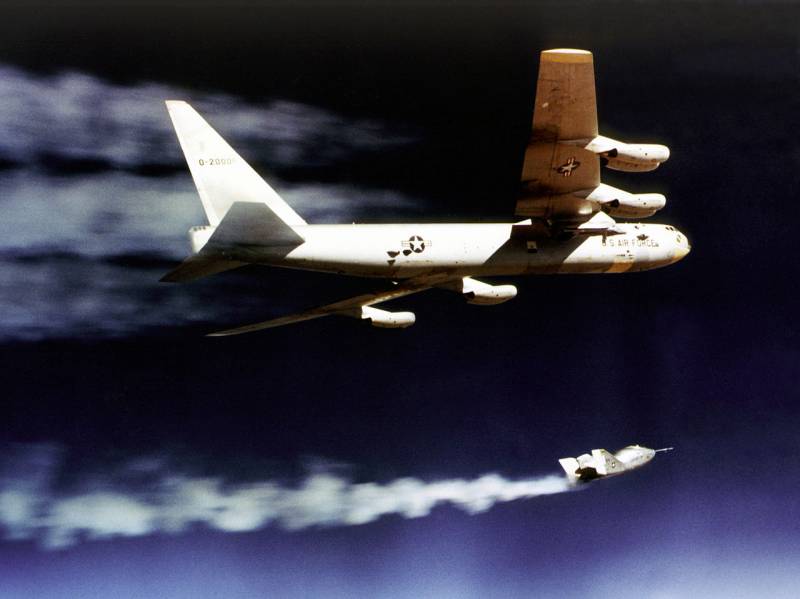
The carrier B-52 resets the experimental X-24A. 1 January 1970
The trials continued at the end of January of the following 1971 year. After a few weeks, test pilots began to storm the line at 1600 km / h. February 18 (23 flight) J. Manke overcame it, speeding up to 1606 km / h. The 25 departure (March 29) reached 1667 km / h. In the future, the aircraft X-24A could not beat this "personal record." In the next flight of 12 May, the maximum altitude was obtained - more than 21,6 km.
The last test flight of the prototype took place on June 4 of the year 1971. This time it accelerated only up to 867 km / h and did not rise above 16,85 km. The duration of the last flight is 517 seconds. This test program has been completed.
Tests of the experimental model Martin Marietta X-24A allowed us to collect a large amount of data on the behavior of the aircraft when flying at different speeds, altitudes and modes. In the future, this information could be used in new projects of aviation or space technology. In addition, soon there was a proposal for the practical verification of another version of the aircraft of a similar purpose.

Lifting body type aircraft: Martin Marietta X-24A, NASA / Northrop M2-F3 and Northrop HL-10
In the fall of 1971, the only built prototype, the X-24A, was returned to the manufacturing company for repairs and upgrades. In the near future, NASA and Martin-Marietta specialists were to develop a new version of the aircraft with a carrier fuselage, based on different principles and having other hull lines. In order to save and speed up construction, it was proposed to build a new prototype based on the old one. The required work took less than two years. In the summer of 1973, a prototype came out for testing, called the X-24B. Despite the widest use of components and assemblies of the existing machine, the new prototype had no noticeable similarity with it.
Over the next few years, NASA and the air force experts tested the new prototype and determined its real capabilities. Testing the X-24B aircraft made it possible to carefully study the new version of the Lifting body scheme and draw conclusions about its real prospects.
The presence of certain experience and proven solutions allowed to implement the project X-24A without any problems. The prototype machine showed itself well and became a very successful flying bench for testing the new aerodynamic appearance. Having completed all the tasks, a single aircraft of this type could be written off, but the responsible persons decided to use it as the basis for the prototype of the new model. In the 1973 year, the rebuilt X-24A re-entered the tests and, for the second time, helped scientists explore new circuit designs for aircraft.
On the materials of the sites:
https://nasa.gov/
http://airwar.ru/
http://astronautix.com/
https://airandspace.si.edu/
At that time, the Air Force Command showed an increased interest in promising aerospace complexes for various purposes. In particular, the possibility of creating reusable spacecraft capable of carrying one or another payload was studied. To simplify the operation, such “space bombers” or other equipment had to be returned to Earth using horizontally flight. The solution of such problems was associated with the need to conduct various studies, both in wind tunnels, and with the use of full-size experimental machines. Looking ahead, it should be noted that work in this direction in the future led to the emergence of the Space Shuttle project, which has come to active operation in the interests of various customers.

Experienced Martin Marietta X-24A at Edwards Air Base
In 1966, NASA, the Air Force, and Martin Marietta jointly implemented the X-23 PRIME research project. His goal was to create a model of the aircraft, built on the scheme of the Lifting body and capable of making a planning flight in the upper atmosphere. Tests of three models of this type showed that it is possible in principle to solve the problems posed, but for this to happen, the existing project needed to be refined in a certain way.
After the tests of the experienced X-23 were completed, the aerospace control, air force and Martin-Marietta signed a new agreement to create an experimental aircraft. The next project received the official "military" designation X-24A. The development company used the working title SV-5J. There were no additional project names or nicknames.
In the framework of the previous project X-23 used so-called. carrying the fuselage, in its form similar to the flying scheme of the aircraft "flying wing". For several reasons, the new project decided to use a different form of the main units and bearing planes. The prospective X-24A prototype should have a drop-like shape without bearing planes made in the form of a traditional wing. At the same time, the use of a stabilizing tail unit was mandatory.
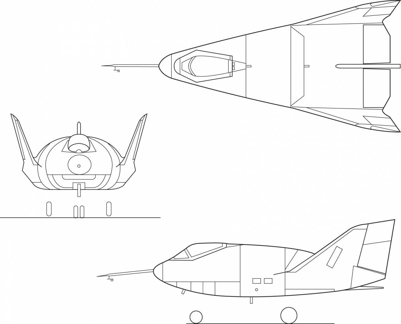
Projection of the aircraft
The X-24A project proposed the construction of an all-metal aircraft adapted to high mechanical, aerodynamic and temperature loads. To obtain high flight characteristics should use a special form of the fuselage and planes. In addition, it was proposed to equip the car with a liquid-propellant rocket engine with sufficient traction characteristics. This technical look has already been used in previous research projects and, in general, has made a good showing.
In accordance with the new objectives of the project and the specifics of the future operation, the new aircraft received the fuselage of the original design, which was noticeably different from the previous "supporting bodies". The proposed all-metal fuselage had a smaller width of the nose and center with a greater height. In the side view, the car looked like a standard wing profile, complemented by a vertical tail.
The nose of the X-24A fuselage had a shape close to a spindle. Immediately behind the rounded side fairing, the upper surface and the bottom of the fuselage diverged, forming a structure with a gradually increasing elliptical section. Then the sides were diluted to form a triangular structure in the plan. The upper part of the fuselage, in turn, noticeably rose upwards. Right behind the nose cone, a straightened bottom began, smoothly connecting to the sides with the help of curved sections of the skin. The width of the flat part of the bottom increased towards the tail. The fuselage tail section had a rectangular shape with a narrowing triangular profile. The tail end of the fuselage was formed by a polygonal opening, enclosed by control planes.

Dashboard
According to its layout, the fuselage of the new flight prototype corresponded to the previous developments of the Lifting body program. The nose part was given under the cockpit, for which there was the instrument compartment. In the tail were placed the engine and fuel tanks. Part of the other volumes in the nose and tail was given under the niche for cleaning the chassis.
In the rear fuselage, on its sides, with a collapse outward, a pair of keels of a large sweep was installed. Behind them were mounted relatively large two-section rudders. In the center of the fuselage, between the main keels, there was another vertical plane. Unlike the other two, it was not completed with a wheel of height. At the same time it had a nozzle of one of the gas rudders. Below the central keel, between two pairs of elevons, were the nozzles of the main engine.
All mechanization and all the steering wheels were located only in the tail of the machine. The pitch and roll control was proposed to be carried out using two pairs of elevons attached between the keels. The first was on the upper surface of the wing and in a neutral position was its continuation. The second one continued to bottom. Aerodynamic rudders were complemented by a pair of nozzles of gas systems of similar purpose.
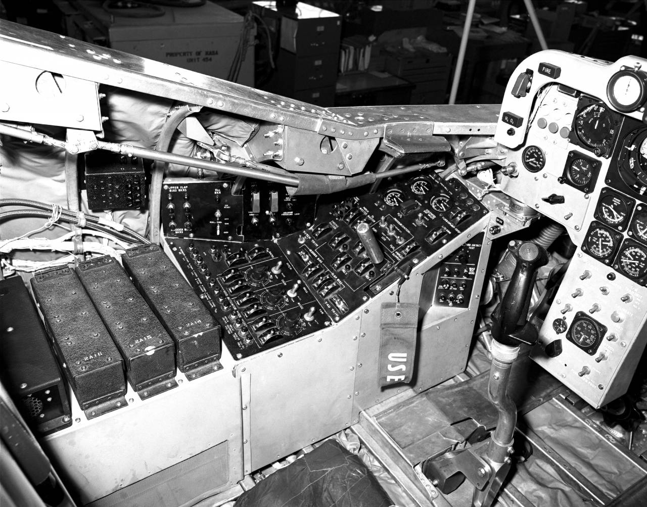
View of the left side of the cabin
The pilot had to work in the nasal single sealed heated cabin. Unlike some previous samples, the cabin was closed by a single large lantern, not divided into several parts. For access to the cockpit, the lantern went up and back with a fairly large section of plating. The large lantern provided a good overview, which made it possible to do without additional glazing in front of the cabin.
The pilot was placed in the ejection seat of the production model. At his workplace there was a dashboard with all the control and navigation devices, as well as a pair of onboard panels. Flight control was carried out using the central knob, engine control knob and a pair of pedals. Also on the dashboard and side panels there were many controls for all onboard systems.
Again, it was proposed to equip the experimental machine with its own power plant. In the rear fuselage placed liquid reaction rocket engine Reaction Motors XLR-11 3600 kgf. The four-chamber engine could be started at the command of the pilot and change the thrust in accordance with the position of the control knob. Also, the engine was associated with gas rudders.

The tail of the X-24A
X-24A received a three-point chassis based on serial components aviation technicians. Under the cockpit was a bow rack with two small-diameter wheels. Under the root of the keels placed a pair of main racks with larger wheels. Using automated drives, all racks retracted into the fuselage by turning back. Niches were covered with rectangular covers of longitudinal arrangement.
From the previous models built as part of the research program, the new aircraft differed not only in shape but also in size. The length of the car was 7,47 m, the maximum width - 3,51 m. Parking height - 2,92 m. The carrier area of the fuselage was brought to 18,1 sq.m. The empty machine weighed 2,88 t. The normal take-off weight is 4,85 t, the maximum one is 5,19 t. According to calculations, the use of the rocket engine made it possible to fly at a speed of more than 1650 km / h. The ceiling exceeded 21 km. Flight planning range, including using a rocket engine, is no more than 72 km.
The small volume of fuel tanks seriously limited the maximum duration of the engine and, as a result, had a negative impact on the possible duration of the flight. Because of this, as part of the Martin Marietta X-24A project, as in other research projects, a separate carrier aircraft should have been used. In a special way, the re-equipped B-52 bomber, using a pylon with docking devices, had to lift the experimental vehicle to a predetermined height and accelerate it to the required speed. Then it was necessary to make an uncoupling, after which the experienced vehicle could independently carry out the flight program and return to the airfield.
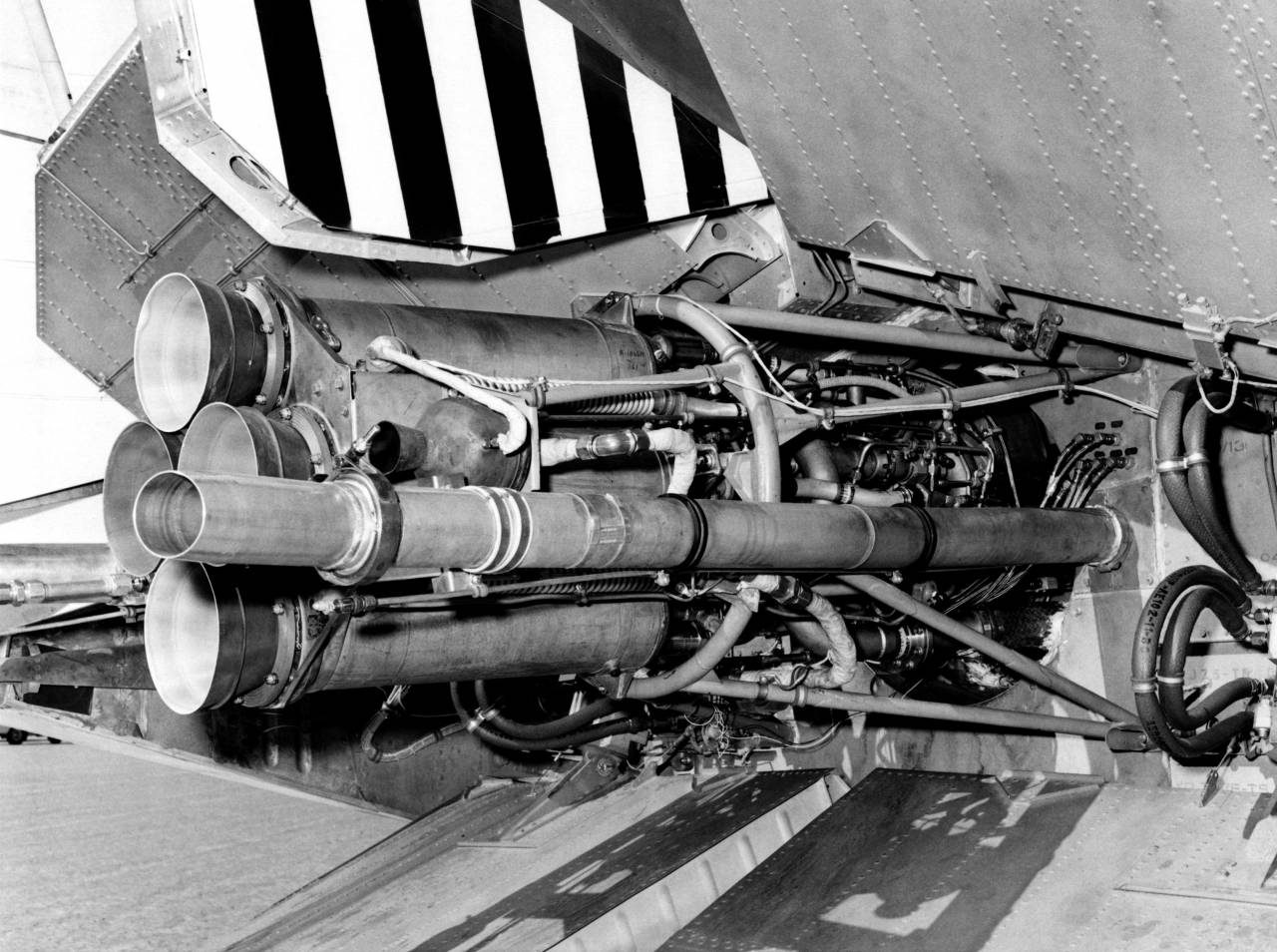
XLR-11 Engine Close Up
The assembly of the only planned experimental glider / rocket plane X-24A was completed at the start of the 1969 year. Soon, the car was delivered to Edwards Air Base, which at that time served as the main testing ground for new aircraft. The tests began with ground tests of the systems and subsequent removal of the prototype by the aircraft carrier. In the course of such tests it was possible to do without any problems. Noticeable design flaws were not identified, which made it possible to begin full-fledged flight tests.
17 April of the same year experienced X-24A first took to the air to carry out independent flight. After the carrier reached an altitude of about 13,7 km and accelerated to 763 km / h, a disengagement occurred, and test pilot Jerry Gentry took control. Over the next few minutes, the glider gradually decreased slowly, while demonstrating the basic features and characteristics. Planning a flight ended with a successful approach to the runway and a soft landing on the chassis. In general, the experimental car showed itself well, although it was possible to reveal some minor flaws.
Over the next few months, J. Gentry and his colleagues completed eight more flights without an engine. According to some data, from a certain time the prototype was loaded with ballast equivalent to the mass of fuel and oxidizer for the engine. In the course of these tests, it was possible to work out all the main aspects of the new project and prepare the machine for subsequent flights using a power plant.

Test Pilot Cecil Powell and Experienced X-24A
During such checks, the glider was able to reach speeds of up to 819 km / h and climb to an altitude of 14,3 km. Both of these records were set in the last 24 flight planning February 1970 of the year. The longest were the third (August 21 1969 of the year) and seventh (November 13) flights. These days, X-24A remained airborne for 4 minutes 30 seconds.
Checks of the experimental aircraft in the configuration of the airframe lasted about 11 months, and after that it became possible to start full-fledged flights. After another drop from the media, which took place on 19 March 1970, the tester J. Gentry started the engine and used it to pick up speed. A significant increase in flight speed allowed to increase the duration of subsequent planning. However, not being able to accelerate further, the rocket glider went to land in just a few minutes. Using the engine, the car was able to develop the speed of 919 km / h and climb to an altitude of 13,5 km. Flight duration - 424 seconds.
About a month later, the 12 flight took place, during which J. Gentry accelerated to 981 km / h and took off to an altitude of 17,59 km. June 17 The 14 flight took place, bringing the project closer to overcoming the sound barrier. Under the control of pilot John Manke, the rocket glider accelerated to 1051 km / h with a maximum altitude of slightly less than 18,6 km.
October 14 1970 of the Year J. Manke performed the 18 test flight. After uncoupling, the experienced X-24A set new records for altitude and speed. The prototype took off to a height of 20,7 km and developed the speed of 1261 km / h, breaking the sound barrier. In October and November, two more supersonic flights took place, during which new results were obtained in terms of the maximum flight altitude.

The carrier B-52 resets the experimental X-24A. 1 January 1970
The trials continued at the end of January of the following 1971 year. After a few weeks, test pilots began to storm the line at 1600 km / h. February 18 (23 flight) J. Manke overcame it, speeding up to 1606 km / h. The 25 departure (March 29) reached 1667 km / h. In the future, the aircraft X-24A could not beat this "personal record." In the next flight of 12 May, the maximum altitude was obtained - more than 21,6 km.
The last test flight of the prototype took place on June 4 of the year 1971. This time it accelerated only up to 867 km / h and did not rise above 16,85 km. The duration of the last flight is 517 seconds. This test program has been completed.
Tests of the experimental model Martin Marietta X-24A allowed us to collect a large amount of data on the behavior of the aircraft when flying at different speeds, altitudes and modes. In the future, this information could be used in new projects of aviation or space technology. In addition, soon there was a proposal for the practical verification of another version of the aircraft of a similar purpose.
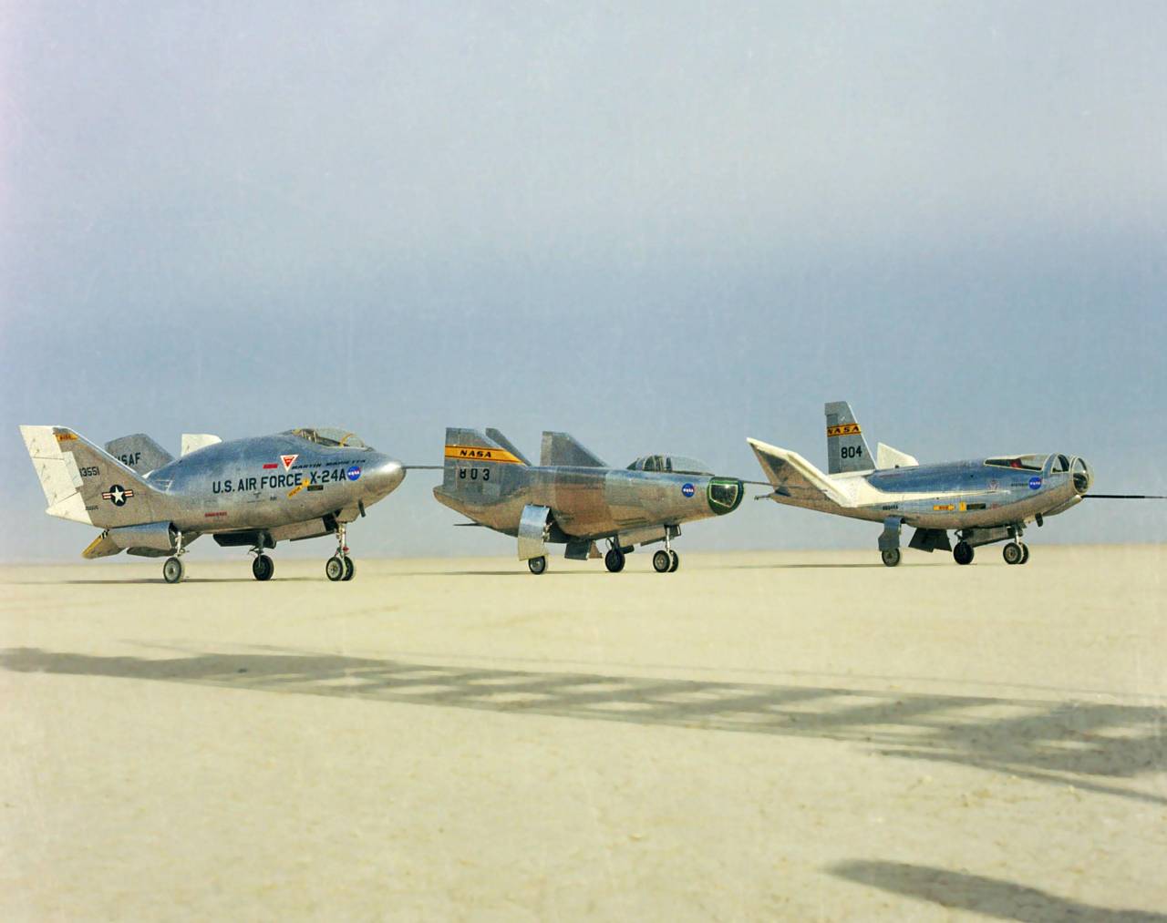
Lifting body type aircraft: Martin Marietta X-24A, NASA / Northrop M2-F3 and Northrop HL-10
In the fall of 1971, the only built prototype, the X-24A, was returned to the manufacturing company for repairs and upgrades. In the near future, NASA and Martin-Marietta specialists were to develop a new version of the aircraft with a carrier fuselage, based on different principles and having other hull lines. In order to save and speed up construction, it was proposed to build a new prototype based on the old one. The required work took less than two years. In the summer of 1973, a prototype came out for testing, called the X-24B. Despite the widest use of components and assemblies of the existing machine, the new prototype had no noticeable similarity with it.
Over the next few years, NASA and the air force experts tested the new prototype and determined its real capabilities. Testing the X-24B aircraft made it possible to carefully study the new version of the Lifting body scheme and draw conclusions about its real prospects.
The presence of certain experience and proven solutions allowed to implement the project X-24A without any problems. The prototype machine showed itself well and became a very successful flying bench for testing the new aerodynamic appearance. Having completed all the tasks, a single aircraft of this type could be written off, but the responsible persons decided to use it as the basis for the prototype of the new model. In the 1973 year, the rebuilt X-24A re-entered the tests and, for the second time, helped scientists explore new circuit designs for aircraft.
On the materials of the sites:
https://nasa.gov/
http://airwar.ru/
http://astronautix.com/
https://airandspace.si.edu/
Information